fuel INFINITI QX56 2011 Factory Service Manual
[x] Cancel search | Manufacturer: INFINITI, Model Year: 2011, Model line: QX56, Model: INFINITI QX56 2011Pages: 5598, PDF Size: 94.53 MB
Page 2932 of 5598

PREPARATIONFL-3
< PREPARATION >
C
DE
F
G H
I
J
K L
M A
FL
NP
O
PREPARATION
PREPARATION
Special Service ToolINFOID:0000000006289680
Commercial Service ToolsINFOID:0000000006289681
Tool number
(Kent-Moore No.)
Tool name
Description
KV10119800
(J-45722)
Fuel tank lock ring wrench Removing and installing fuel tank rock ring
a: 187 mm (7.36 in)
NOTE:
The actual shapes of Kent-Moore No. tools
may differ from those of the special tools illus-
trated here.
JSBIA0383ZZ
Tool name Description
Power tool Loosening bolts and nuts
PBIC0190E
Revision: 2010 May2011 QX56
Page 2933 of 5598
FL-4
< PERIODIC MAINTENANCE >
FUEL SYSTEM
PERIODIC MAINTENANCE
FUEL SYSTEM
InspectionINFOID:0000000006289682
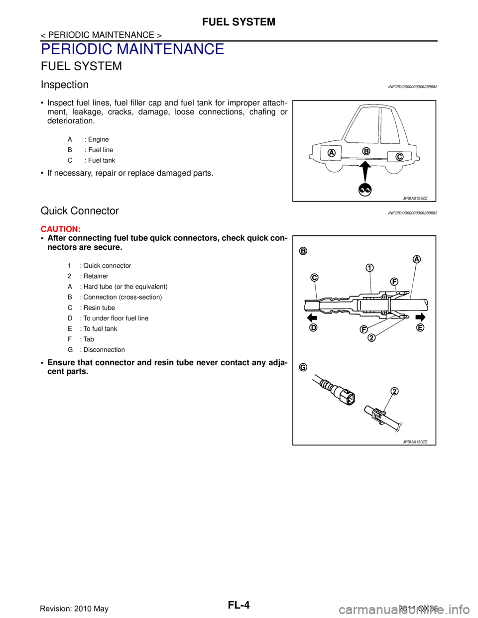
• Inspect fuel lines, fuel filler cap and fuel tank for improper attach-ment, leakage, cracks, damage, loose connections, chafing or
deterioration.
If necessary, repair or replace damaged parts.
Quick ConnectorINFOID:0000000006289683
CAUTION:
After connecting fuel tube quick connectors, check quick con-
nectors are secure.
Ensure that connector and resi n tube never contact any adja-
cent parts.
A : Engine
B : Fuel line
C: Fuel tank
JPBIA0129ZZ
1 : Quick connector
2: Retainer
A : Hard tube (or the equivalent)
B : Connection (cross-section)
C : Resin tube
D : To under floor fuel line
E : To fuel tank
F: Tab
G : Disconnection
JPBIA0130ZZ
Revision: 2010 May2011 QX56
Page 2934 of 5598
FUEL LEVEL SENSOR UNIT, FUEL FILTER AND FUEL PUMP ASSEMBLY
FL-5
< REMOVAL AND INSTALLATION >
C
D E
F
G H
I
J
K L
M A
FL
NP
O
REMOVAL AND INSTALLATION
FUEL LEVEL SENSOR UNIT, FUEL FI
LTER AND FUEL PUMP ASSEMBLY
Exploded ViewINFOID:0000000006289684
Removal and InstallationINFOID:0000000006289685
WARNING:
Be sure to read “General Precautions” wh en working on the fuel system. Refer to FL-2, "
General Pre-
cautions".
REMOVAL
1. Check fuel level on a level ground. If the fuel level is 7/8 of the fuel tank (full or nearly full), draw appropri-
ate amount of fuel from the fuel tank.
In the event of malfunction in fuel pump, insert a hose measuring 20mm (0.79 in) in diameter into the
filler opening to draw approximately 20 liters fuel.
2. Release the fuel pressure from the fuel lines. Refer to EC-153, "
Work Procedure".
3. Open fuel filler lid.
4. Open filler cap and release the pressure inside fuel tank.
5. Tilt the second seat toward the front of the vehicle.
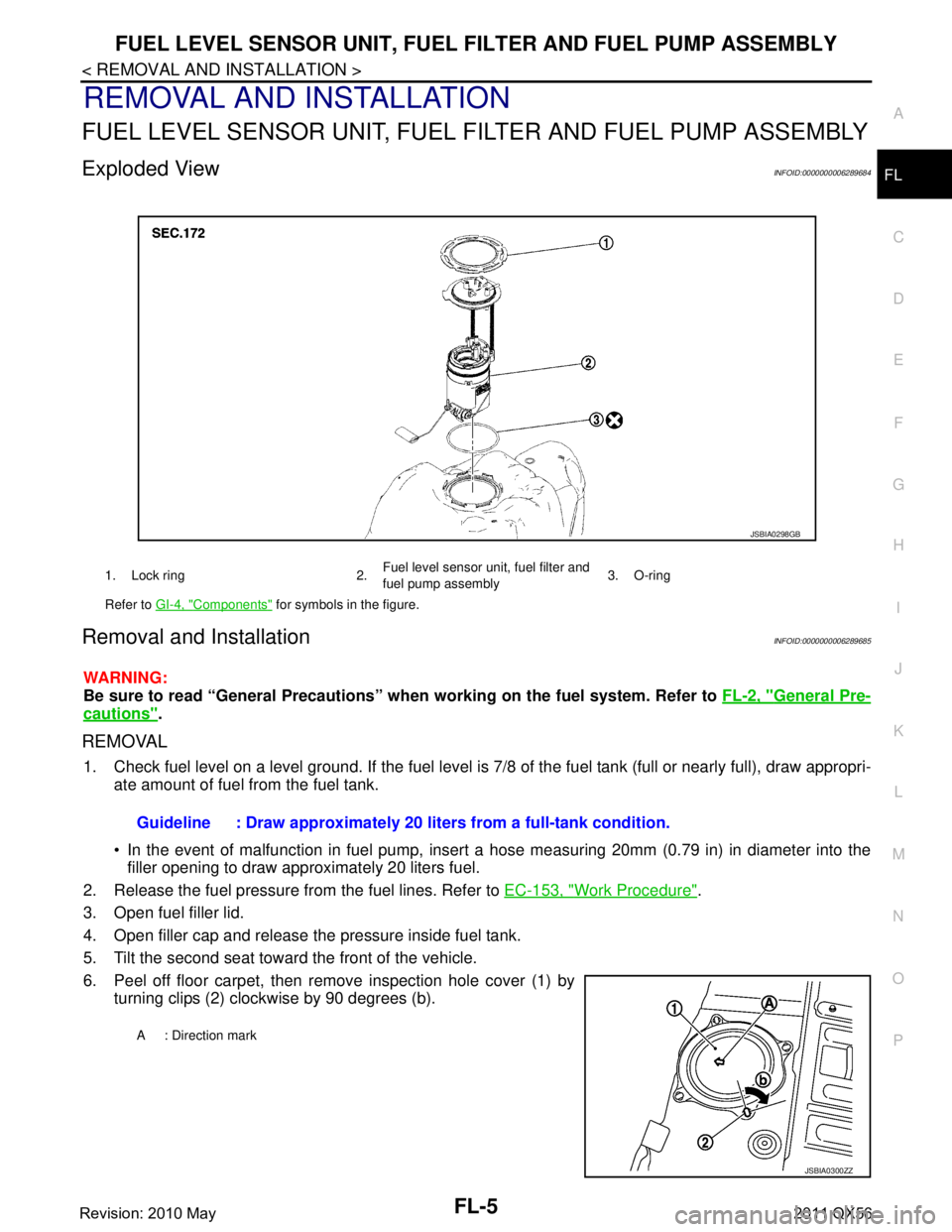
6. Peel off floor carpet, then remove inspection hole cover (1) by turning clips (2) clockwise by 90 degrees (b).
1. Lock ring 2. Fuel level sensor unit, fuel filter and
fuel pump assembly3. O-ring
Refer to GI-4, "
Components" for symbols in the figure.
JSBIA0298GB
Guideline : Draw approximately 20 li ters from a full-tank condition.
A : Direction mark
JSBIA0300ZZ
Revision: 2010 May2011 QX56
Page 2935 of 5598
FL-6
< REMOVAL AND INSTALLATION >
FUEL LEVEL SENSOR UNIT, FUEL FILTER AND FUEL PUMP ASSEMBLY
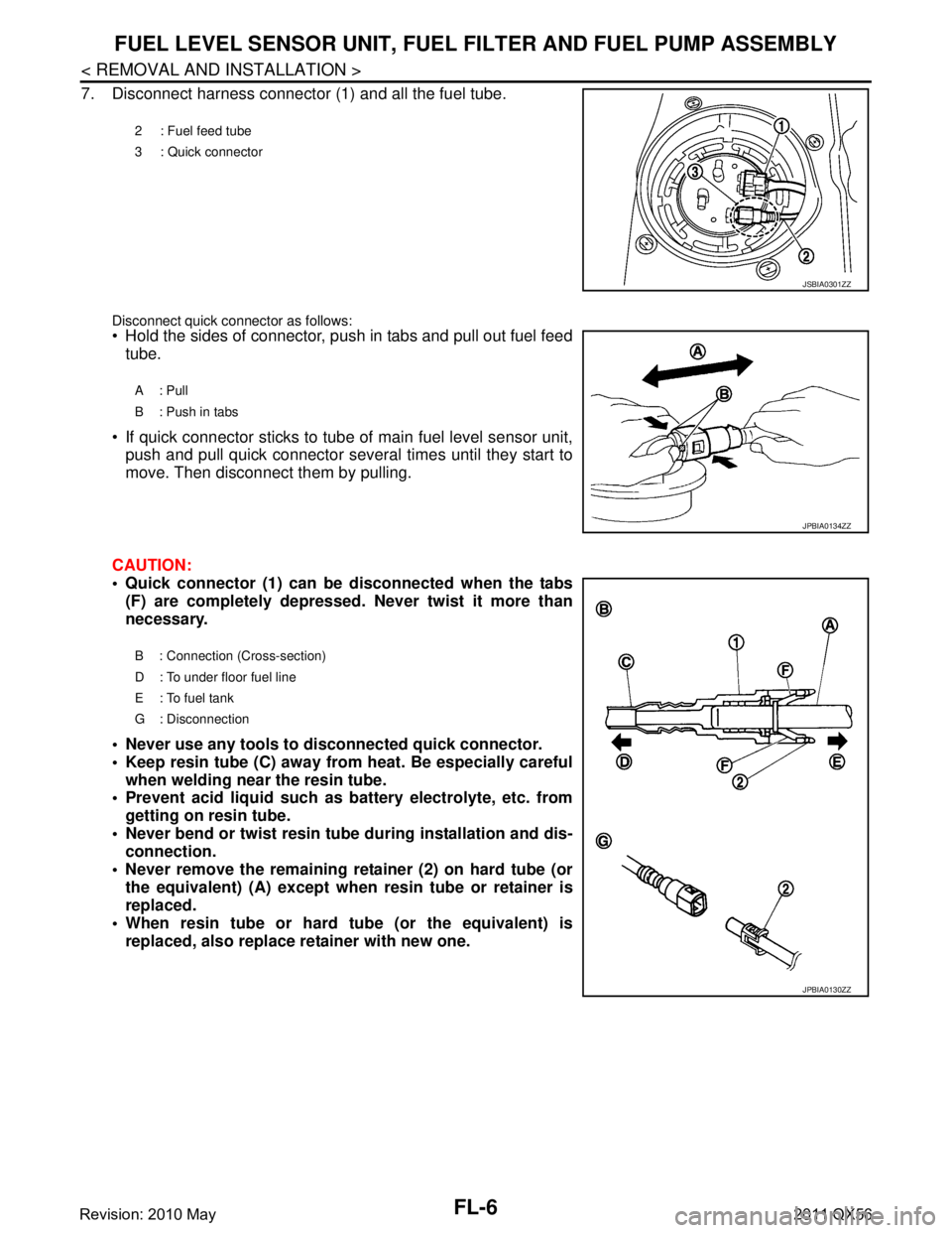
7. Disconnect harness connector (1) and all the fuel tube.
Disconnect quick connector as follows: Hold the sides of connector, push in tabs and pull out fuel feed
tube.
If quick connector sticks to tube of main fuel level sensor unit, push and pull quick connector several times until they start to
move. Then disconnect them by pulling.
CAUTION:
Quick connector (1) can be disconnected when the tabs (F) are completely depressed. Never twist it more than
necessary.
Never use any tools to di sconnected quick connector.
Keep resin tube (C) away from heat. Be especially careful when welding near the resin tube.
Prevent acid liquid such as battery electrolyte, etc. from
getting on resin tube.
Never bend or twist resin tube during installation and dis- connection.
Never remove the remaining retainer (2) on hard tube (or the equivalent) (A) except when resin tube or retainer is
replaced.
When resin tube or hard tube (or the equivalent) is replaced, also replace retainer with new one.
2 : Fuel feed tube
3 : Quick connector
JSBIA0301ZZ
A: Pull
B : Push in tabs
JPBIA0134ZZ
B : Connection (Cross-section)
D : To under floor fuel line
E : To fuel tank
G : Disconnection
JPBIA0130ZZ
Revision: 2010 May2011 QX56
Page 2936 of 5598
FUEL LEVEL SENSOR UNIT, FUEL FILTER AND FUEL PUMP ASSEMBLY
FL-7
< REMOVAL AND INSTALLATION >
C
D E
F
G H
I
J
K L
M A
FL
NP
O
To keep the connecting portio
n clean and to avoid dam-
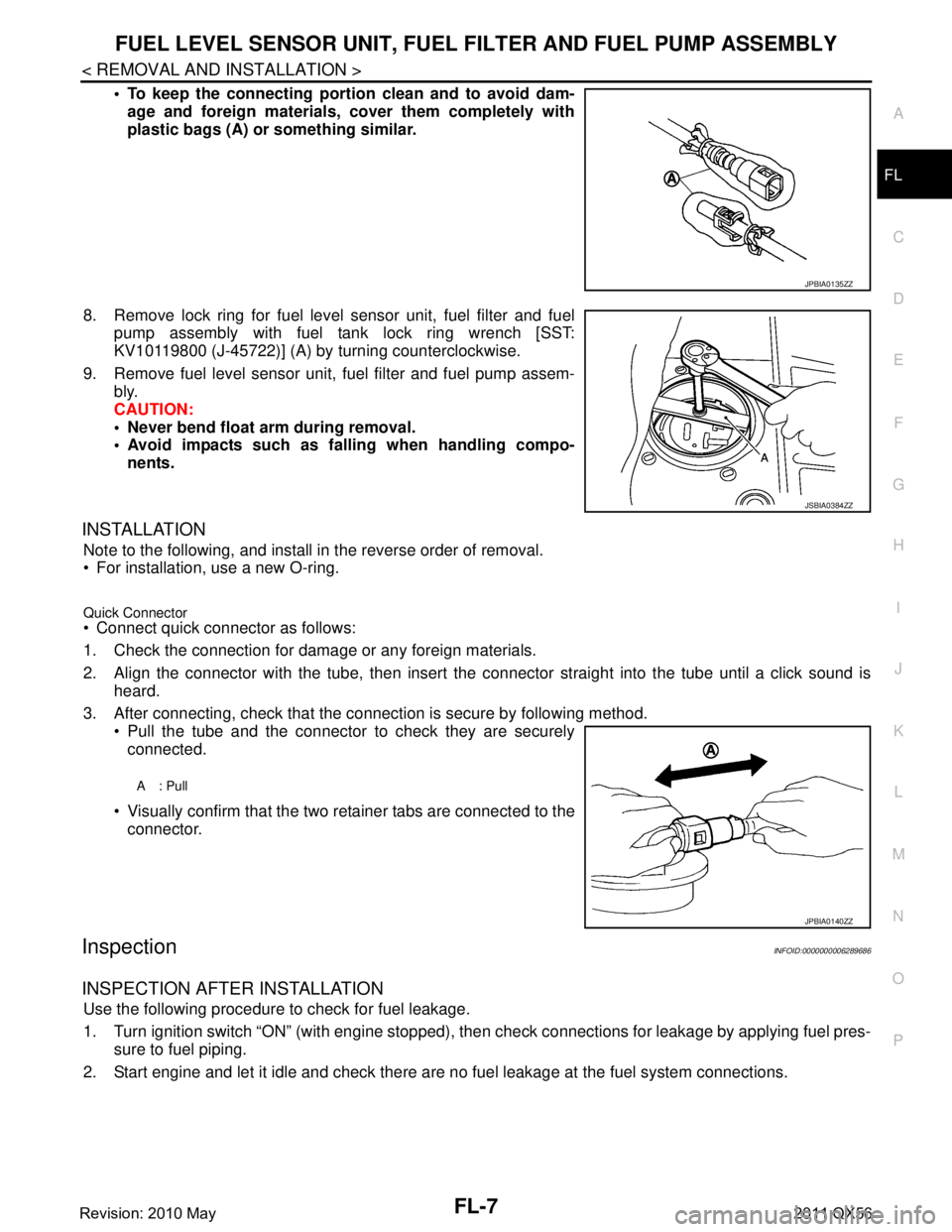
age and foreign materials, cover them completely with
plastic bags (A) or something similar.
8. Remove lock ring for fuel level sensor unit, fuel filter and fuel pump assembly with fuel tank lock ring wrench [SST:
KV10119800 (J-45722)] (A) by turning counterclockwise.
9. Remove fuel level sensor unit, fuel filter and fuel pump assem- bly.
CAUTION:
Never bend float arm during removal.
Avoid impacts such as fa lling when handling compo-
nents.
INSTALLATION
Note to the following, and install in the reverse order of removal.
For installation, use a new O-ring.
Quick Connector Connect quick connector as follows:
1. Check the connection for damage or any foreign materials.
2. Align the connector with the tube, then insert the connector straight into the tube until a click sound is
heard.
3. After connecting, check that the connection is secure by following method. Pull the tube and the connector to check they are securely
connected.
Visually confirm that the two retainer tabs are connected to the connector.
InspectionINFOID:0000000006289686
INSPECTION AFTER INSTALLATION
Use the following procedure to check for fuel leakage.
1. Turn ignition switch “ON” (with engine stopped), then check connections for leakage by applying fuel pres-
sure to fuel piping.
2. Start engine and let it idle and check there are no fuel leakage at the fuel system connections.
JPBIA0135ZZ
JSBIA0384ZZ
A: Pull
JPBIA0140ZZ
Revision: 2010 May2011 QX56
Page 2937 of 5598
FL-8
< REMOVAL AND INSTALLATION >
FUEL TANK
FUEL TANK
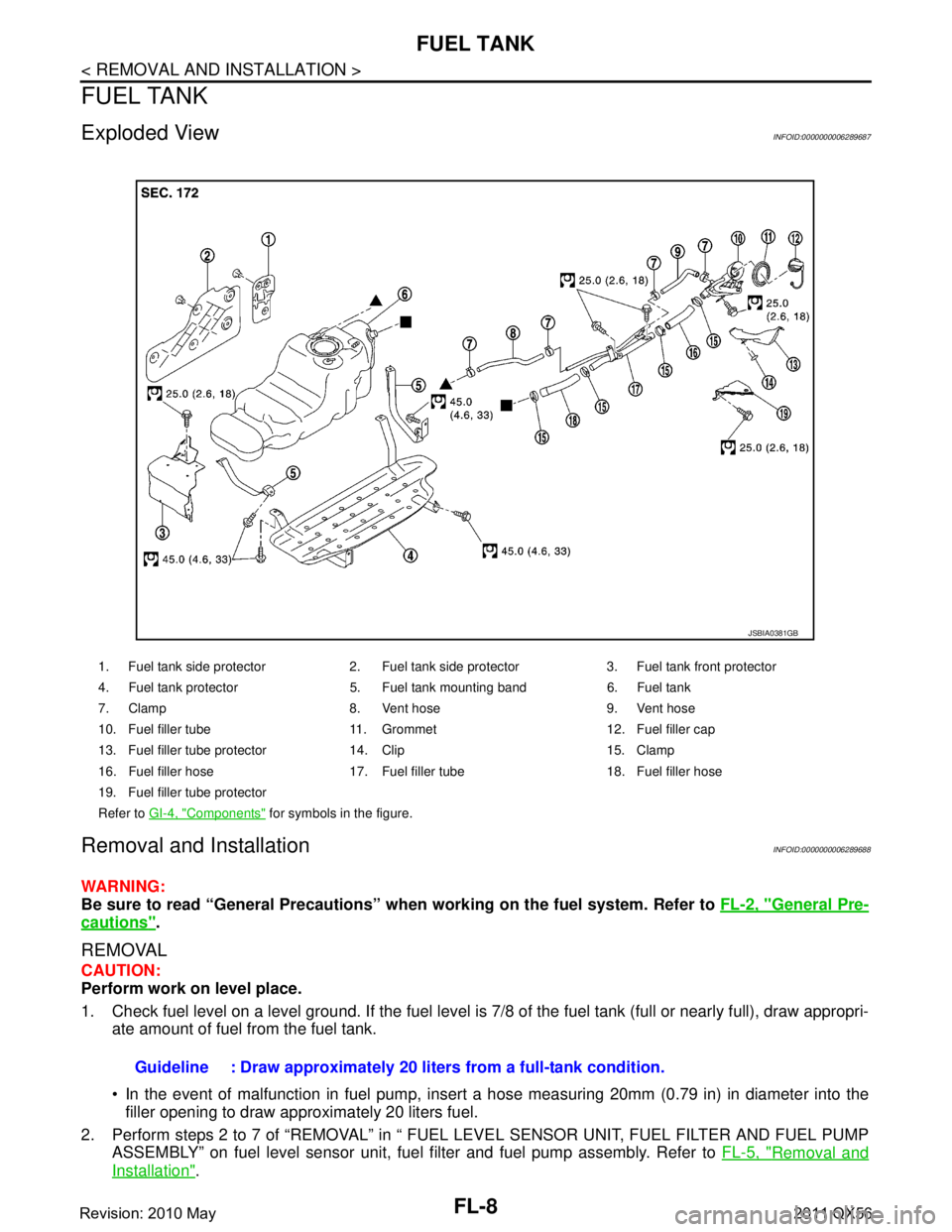
Exploded ViewINFOID:0000000006289687
Removal and InstallationINFOID:0000000006289688
WARNING:
Be sure to read “General Precautions” when working on the fuel system. Refer to FL-2, "
General Pre-
cautions".
REMOVAL
CAUTION:
Perform work on level place.
1. Check fuel level on a level ground. If the fuel level is 7/8 of the fuel tank (full or nearly full), draw appropri-
ate amount of fuel from the fuel tank.
In the event of malfunction in fuel pump, insert a hose measuring 20mm (0.79 in) in diameter into the
filler opening to draw approximately 20 liters fuel.
2. Perform steps 2 to 7 of “REMOVAL” in “ FUEL LEVEL SENSOR UNIT, FUEL FILTER AND FUEL PUMP ASSEMBLY” on fuel level sensor unit, fuel filter and fuel pump assembly. Refer to FL-5, "
Removal and
Installation".
1. Fuel tank side protector 2. Fuel tank side protector 3. Fuel tank front protector
4. Fuel tank protector 5. Fuel tank mounting band 6. Fuel tank
7. Clamp 8. Vent hose 9. Vent hose
10. Fuel filler tube 11. Grommet 12. Fuel filler cap
13. Fuel filler tube protector 14. Clip 15. Clamp
16. Fuel filler hose 17. Fuel filler tube 18. Fuel filler hose
19. Fuel filler tube protector
Refer to GI-4, "
Components" for symbols in the figure.
JSBIA0381GB
Guideline : Draw approximately 20 li ters from a full-tank condition.
Revision: 2010 May2011 QX56
Page 2938 of 5598

FUEL TANKFL-9
< REMOVAL AND INSTALLATION >
C
DE
F
G H
I
J
K L
M A
FL
NP
O
3. Remove LH rear wheel and tire.
4. Disconnect fuel filler hose, vent hose and EVAP hose at fuel tank side.
5. Remove fuel tank protector.
6. Remove the fuel tank mounting band bolts while supporting the
fuel tank with a suitable lift jack.
CAUTION:
Support the position that fu el tank mounting bands never
engage.
7. Supporting with hands, descend suitable jack carefully, and remove fuel tank. CAUTION:
Check that all connection po ints have been disconnected.
Confirm there is no interference with vehicle.
InspectionINFOID:0000000006289689
INSPECTION AFTER INSTALLATION
Use the following procedure to check for fuel leakage.
1. Turn ignition switch “ON” (with engine stopped), and check connections for leakage by applying fuel pres-
sure to fuel piping.
2. Start engine and rev it up and check there are no f uel leakage at the fuel system tube and hose connec-
tions.
After removing/installing rear suspension assembly, check to adjust wheel alignment. Refer to RSU-6,
"Inspection".
LBIA0413E
Revision: 2010 May2011 QX56
Page 2942 of 5598

SERVICE DATA AND SPECIFICATIONS (SDS)
FL-13
< SERVICE DATA AND SPECIFICATIONS (SDS)
C
D E
F
G H
I
J
K L
M A
FL
NP
O
SERVICE DATA AND SPECIFICATIONS (SDS)
SERVICE DATA AND SPECIFICATIONS (SDS)
Fuel TankINFOID:0000000006289690
Standard and Limit
Fuel tank capacity
Approx. 98.4 (26 US gal)
Fuel recommendation Refer to GI-31, "
Fuel"
Revision: 2010 May2011 QX56
Page 2945 of 5598
PRECAUTIONSFSU-3
< PRECAUTION >
C
DF
G H
I
J
K L
M A
B
FSU
N
O P
5. When the repair work is completed, re-connect both battery cables. With the brake pedal released, turn
the push-button ignition switch from ACC position to ON position, then to LOCK position. (The steering
wheel will lock when the push-button ignition switch is turned to LOCK position.)
6. Perform self-diagnosis check of a ll control units using CONSULT-III.
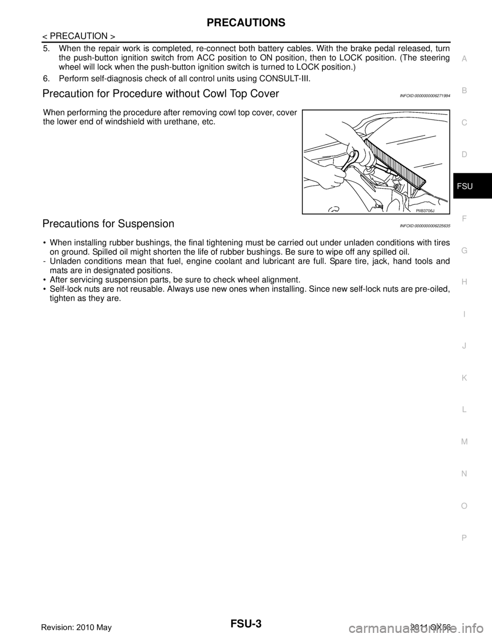
Precaution for Procedure without Cowl Top CoverINFOID:0000000006271994
When performing the procedure after removing cowl top cover, cover
the lower end of windshield with urethane, etc.
Precautions for SuspensionINFOID:0000000006225635
When installing rubber bushings, the final tightening mu st be carried out under unladen conditions with tires
on ground. Spilled oil might shorten the life of rubb er bushings. Be sure to wipe off any spilled oil.
- Unladen conditions mean that fuel, engine coolant and l ubricant are full. Spare tire, jack, hand tools and
mats are in designated positions.
After servicing suspension parts, be sure to check wheel alignment.
Self-lock nuts are not reusable. Always use new ones w hen installing. Since new self-lock nuts are pre-oiled,
tighten as they are.
PIIB3706J
Revision: 2010 May2011 QX56
Page 2949 of 5598
WHEEL ALIGNMENTFSU-7
< PERIODIC MAINTENANCE >
C
DF
G H
I
J
K L
M A
B
FSU
N
O P
WHEEL ALIGNMENT
InspectionINFOID:0000000006225640
DESCRIPTION
Measure wheel alignment under unladen conditions.
NOTE:
“Unladen conditions” means that fuel, engine coolant, and lubricant are full. Spare tire, jack, hand tools and
mats are in designated positions.
PRELIMINARY CHECK
Check the following:
Tires for improper air pressure and wear
Road wheels for runout: Refer to WT-64, "
Inspection".
Wheel bearing axial end play: Refer to FA X - 7 , "
Inspection" (2WD), FAX-16, "Inspection" (4WD).
Lower link and upper link ball joint axial end play: Refer to FSU-15, "
Inspection" and FSU-18, "Inspection".
Shock absorber operation.
Each mounting part of axle and suspension for looseness and deformation
Lower link for cracks, deformation and other damage
Vehicle height (posture)
GENERAL INFORMATION AND RECOMMENDATIONS
A four-wheel thrust alignment should be performed.
- This type of alignment is recomm ended for any NISSAN/INFINITI vehicle.
- The four-wheel “thrust” process helps ensure that t he vehicle is properly aligned and the steering wheel is
centered.
- The alignment rack itself should be capable of accepting any NISSAN/INFINITI vehicle.
- The rack should be checked to ensure that it is level.
Make sure the machine is properly calibrated.
- Your alignment equipment should be regularly ca librated in order to give correct information.
- Check with the manufacturer of your specific equi pment for their recommended Service/Calibration Sched-
ule.
ALIGNMENT PROCESS
IMPORTANT:
Use only the alignment specificati ons listed in this Service Manual.
When displaying the alignment settings, many alignment machines use “indicators”: (Green/red, plus or
minus, Go/No Go). Never use these indicators.
- The alignment specifications programmed into your machine that operate these indicators may not be cor-
rect.
- This may result in an ERROR.
Some newer alignment machines are equipped with an optional “Rolling Compensation” method to “com-
pensate” the sensors (alignment targets or head units). Never use this “Rolling Compensation” method.
- Use the “Jacking Compensation Method”. After installi ng the alignment targets or head units, raise the vehi-
cle and rotate the wheels 1/2 turn both ways.
- See Instructions in the alignment machine you're using for more information on this.
AdjustmentINFOID:0000000006225641
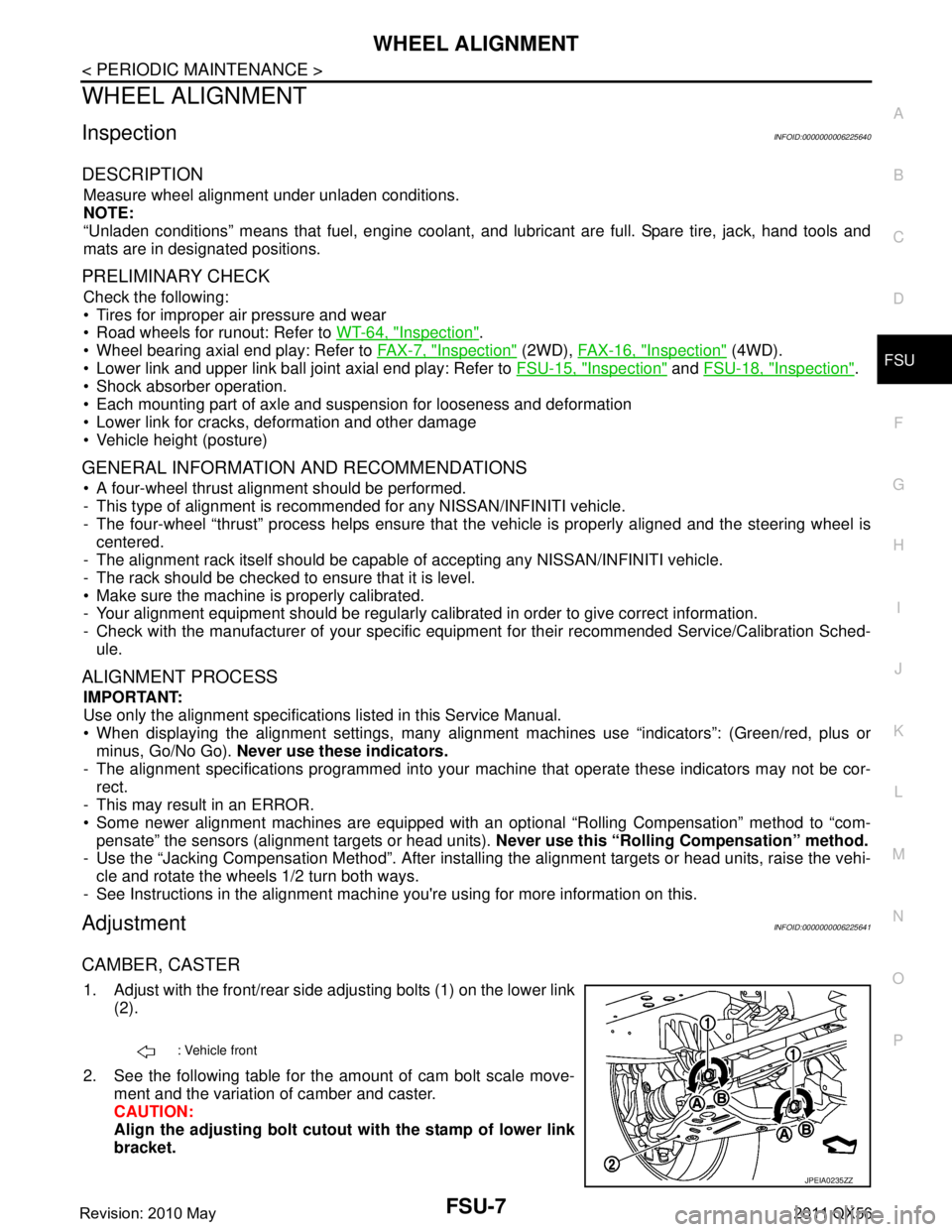
CAMBER, CASTER
1. Adjust with the front/rear side adjusting bolts (1) on the lower link
(2).
2. See the following table for the amount of cam bolt scale move- ment and the variation of camber and caster.
CAUTION:
Align the adjusting bolt cutout with the stamp of lower link
bracket.
: Vehicle front
JPEIA0235ZZ
Revision: 2010 May2011 QX56