timing belt INFINITI QX56 2011 Factory Service Manual
[x] Cancel search | Manufacturer: INFINITI, Model Year: 2011, Model line: QX56, Model: INFINITI QX56 2011Pages: 5598, PDF Size: 94.53 MB
Page 3 of 5598

QUICK REFERENCE CHART QX56
QUICK REFERENCE CHART QX56PFP:00000
ENGINE TUNE-UP DATA (VK56VD)ELS0003W
Engine modelVK56VD
Firing order 1-8-7-3-6-5-4-2
Idle speed
A/T (In “P or N” position) rpm
600 ± 50
Ignition timing
(BTDC at idle speed) 12
° ± 2 °
CO% at idle 0.7 - 9.9 % and engine runs smoothly
Tensions of drive belt Auto adjustment by auto tensioner
Radiater cap relief pressure kPa (kg/cm
2 , psi)
Standard 108.2 - 127.8 (1.1 - 1.3, 15.7 - 18.5)
Limit 98 (1.0, 14)
Cooling system leakage testing pressure kPa (kg/cm
2 , psi)186 (1.9, 27)
Compression pressure kPa (kg/cm
2 , psi)/rpm
Standard 1,667 (17, 242)/200
Minimum 1,226 (12.5, 178)/200
Differential limit between cylinders 98 (1.0, 14)/200
Spark plug
(Iridium-tipped type) Make NGK
Standard type DILKAR7B11
Gap (Standard) mm (in) 1.1 (0.043)
2011
Page 2025 of 5598
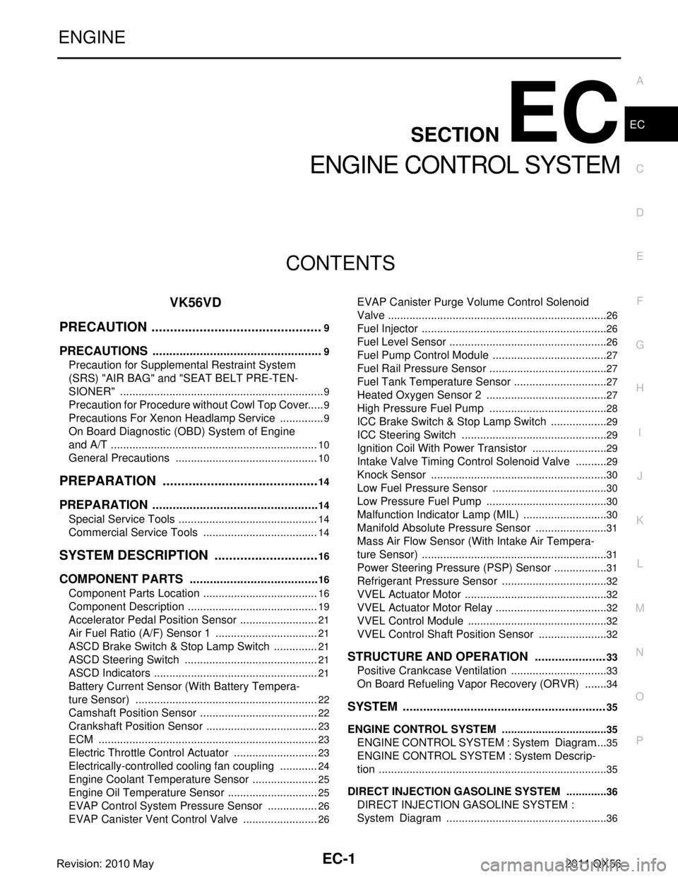
EC-1
ENGINE
C
DE
F
G H
I
J
K L
M
SECTION EC
A
EC
N
O P
CONTENTS
ENGINE CONTROL SYSTEM
VK56VD
PRECAUTION ................ ...............................
9
PRECAUTIONS .............................................. .....9
Precaution for Supplemental Restraint System
(SRS) "AIR BAG" and "SEAT BELT PRE-TEN-
SIONER" ............................................................. ......
9
Precaution for Procedure without Cowl Top Cover ......9
Precautions For Xenon Headlamp Service ...............9
On Board Diagnostic (OBD) System of Engine
and A/T ....................................................................
10
General Precautions ...............................................10
PREPARATION ...........................................14
PREPARATION .............................................. ....14
Special Service Tools .......................................... ....14
Commercial Service Tools ......................................14
SYSTEM DESCRIPTION .............................16
COMPONENT PARTS ................................... ....16
Component Parts Location .................................. ....16
Component Description ...........................................19
Accelerator Pedal Position Sensor ..........................21
Air Fuel Ratio (A/F) Sensor 1 ..................................21
ASCD Brake Switch & Stop Lamp Switch ...............21
ASCD Steering Switch ............................................21
ASCD Indicators ......................................................21
Battery Current Sensor (With Battery Tempera-
ture Sensor) ............................................................
22
Camshaft Position Sensor .......................................22
Crankshaft Position Sensor .....................................23
ECM ........................................................................23
Electric Throttle Control Actuator ............................23
Electrically-controlled cooling fan coupling .............24
Engine Coolant Temperature Sensor ......................25
Engine Oil Temperature Sensor ..............................25
EVAP Control System Pressure Sensor .................26
EVAP Canister Vent Control Valve .........................26
EVAP Canister Purge Volume Control Solenoid
Valve .................................................................... ....
26
Fuel Injector .............................................................26
Fuel Level Sensor ....................................................26
Fuel Pump Control Module ......................................27
Fuel Rail Pressure Sensor .......................................27
Fuel Tank Temperature Sensor ...............................27
Heated Oxygen Sensor 2 ........................................27
High Pressure Fuel Pump .......................................28
ICC Brake Switch & Stop Lamp Switch ...................29
ICC Steering Switch ................................................29
Ignition Coil With Power Transistor .........................29
Intake Valve Timing Control Solenoid Valve ...........29
Knock Sensor ...................................................... ....30
Low Fuel Pressure Sensor ......................................30
Low Pressure Fuel Pump ........................................30
Malfunction Indicator Lamp (MIL) ............................30
Manifold Absolute Pressure Sensor ........................31
Mass Air Flow Sensor (With Intake Air Tempera-
ture Sensor) .............................................................
31
Power Steering Pressure (PSP) Sensor ..................31
Refrigerant Pressure Sensor ............................... ....32
VVEL Actuator Motor ...............................................32
VVEL Actuator Motor Relay .....................................32
VVEL Control Module ..............................................32
VVEL Control Shaft Position Sensor .......................32
STRUCTURE AND OPERATION .....................33
Positive Crankcase Ventilation ................................33
On Board Refueling Vapor Recovery (ORVR) ........34
SYSTEM ............................................................35
ENGINE CONTROL SYSTEM ........................ ...........35
ENGINE CONTROL SYSTEM : System Diagram ....35
ENGINE CONTROL SYSTEM : System Descrip-
tion ...........................................................................
35
DIRECT INJECTION GASOLINE SYSTEM .......... ....36
DIRECT INJECTION GASOLINE SYSTEM :
System Diagram .....................................................
36
Revision: 2010 May2011 QX56
Page 2190 of 5598
![INFINITI QX56 2011 Factory Service Manual
EC-166
< DTC/CIRCUIT DIAGNOSIS >[VK56VD]
TROUBLE DIAGNOSIS - SPECIFICATION VALUE
1. Check for the cause of large engine friction. Refer to the following.
- Engine oil level is too high
- Engine oil v INFINITI QX56 2011 Factory Service Manual
EC-166
< DTC/CIRCUIT DIAGNOSIS >[VK56VD]
TROUBLE DIAGNOSIS - SPECIFICATION VALUE
1. Check for the cause of large engine friction. Refer to the following.
- Engine oil level is too high
- Engine oil v](/img/42/57033/w960_57033-2189.png)
EC-166
< DTC/CIRCUIT DIAGNOSIS >[VK56VD]
TROUBLE DIAGNOSIS - SPECIFICATION VALUE
1. Check for the cause of large engine friction. Refer to the following.
- Engine oil level is too high
- Engine oil viscosity
- Belt tension of power steering, alternat
or, A/C compressor, etc. is excessive
- Noise from engine
- Noise from transmission, etc.
2. Check for the cause of insufficient combustion. Refer to the following.
- Valve clearance malfunction
- Intake valve timing control function malfunction
- Camshaft sprocket installation malfunction, etc.
>> Repair or replace malfunctioning part, and then GO TO 27.
16.CHECK INTAKE SYSTEM
Check for the cause of uneven air flow through mass air flow sensor. Refer to the following.
Crushed air ducts
Malfunctioning seal of air cleaner element
Uneven dirt of air cleaner element
Improper specification of intake air system
Is the inspection result normal?
YES >> GO TO 18.
NO >> Repair or replace malfunctioning part, and then GO TO 17.
17.CHECK “A/F ALPHA-B1”, “A/F ALPHA-B2” AND “B/FUEL SCHDL”
Select “A/F ALPHA-B1”, “A/F ALPHA-B2” and “B/FUE L SCHDL” in “SPEC” of “DATA MONITOR” mode, and
check that each indication is within the SP value.
Is the measurement value within the SP value?
YES >> INSPECTION END
NO >> “B/FUEL SCHDL” is more, “A/F ALPHA-B1” and “A /F ALPHA-B2” are less than the SP value: GO
TO 18.
18.DISCONNECT AND RECONNECT MASS AIR FLOW SENSOR HARNESS CONNECTOR
1. Stop the engine.
2. Disconnect mass air flow sensor harness connector. Check pin terminal and connector for damage and then reconnect it again.
>> GO TO 19.
19.CHECK “A/F ALPHA-B1” AND “A/F ALPHA-B2”
1. Start engine.
2. Select “A/F ALPHA-B1” and “A/F ALPHA-B2” in “ SPEC” of “DATA MONITOR” mode, and check that each
indication is within the SP value.
Is the measurement value within the SP value?
YES >> Detect malfunctioning part of mass air flow sensor circuit and repair it. Refer to EC-201, "Diagno-
sis Procedure". Then GO TO 26.
NO >> GO TO 20.
20.CHECK “MAS A/F SE-B1”
Select “MAS A/F SE-B1” in “SPEC” of “DATA MONITOR” mode, and check that the indication is within the SP
value.
Is the measurement value within the SP value?
YES >> GO TO 21.
NO >> More than the SP value: Replace malfuncti oning mass air flow sensor, and then GO TO 26.
21.REPLACE ECM
1. Replace ECM.
2. Perform EC-143, "
Work Procedure".
Revision: 2010 May2011 QX56
Page 2564 of 5598

EM-2
Removal and Installation ........................................30
ROCKER COVER ..............................................33
Exploded View ..................................................... ...33
Removal and Installation ........................................33
VVEL ACTUATOR ASSEMBLY ........................36
Exploded View ..................................................... ...36
Removal and Installation ........................................36
Inspection ...............................................................39
EXHAUST MANIFOLD AND THREE WAY
CATALYST ........................................................
40
Exploded View ..................................................... ...40
Removal and Installation ........................................40
Inspection ...............................................................42
HIGH PRESSURE FUEL PUMP AND FUEL
HOSE .................................................................
43
Exploded View ..................................................... ...43
Removal and Installation ........................................43
Inspection ...............................................................46
FUEL INJECTOR AND FUEL TUBE .................48
Exploded View ..................................................... ...48
Removal and Installation ........................................49
Inspection ...............................................................53
OIL PAN (LOWER) AND OIL STRAINER .........54
Exploded View ..................................................... ...54
Removal and Installation ........................................55
Inspection ...............................................................56
OIL PAN (UPPER) .......................................... ...57
Exploded View ..................................................... ...57
Removal and Installation ........................................58
Inspection ...............................................................60
TIMING CHAIN ............................................... ...61
Exploded View ..................................................... ...61
Removal and Installation ........................................62
Inspection ...............................................................72
CAMSHAFT .......................................................74
Exploded View ..................................................... ...74
Removal and Installation ........................................75
Inspection ...............................................................77
CYLINDER HEAD ..............................................86
Exploded View ..................................................... ...86
Removal and Installation ........................................87
Disassembly and Assembly ....................................89
Inspection ............................................................. ...92
OIL SEAL ...........................................................96
FRONT OIL SEAL .................................................. ...96
FRONT OIL SEAL : Removal and Installation ........96
REAR OIL SEAL .................................................... ...96
REAR OIL SEAL : Removal and Installation ...........97
UNIT REMOVAL AND INSTALLATION ....98
ENGINE ASSEMBL Y ..................................... ...98
Exploded View ..................................................... ...98
Removal and Installation .........................................99
Inspection ..............................................................102
UNIT DISASSEMBLY AND ASSEMBLY ..103
ENGINE STAND SETTING ..............................103
Setting .................................................................. .103
ENGINE UNIT ...................................................105
Disassembly ......................................................... .105
Assembly ..............................................................105
CYLINDER BLOCK ..........................................106
Exploded View ..................................................... .106
Disassembly and Assembly ..................................107
Inspection ..............................................................115
HOW TO SELECT PISTON AND BEARING ...125
Description ........................................................... .125
Piston ....................................................................125
Connecting Rod Bearing .....................................126
Main Bearing ........................................................128
SERVICE DATA AND SPECIFICATIONS
(SDS) ........ .................................................
132
SERVICE DATA AND SPECIFICATIONS
(SDS) .............................................................. ..
132
General Specification .......................................... .132
Drive Belts .............................................................132
Spark Plug ............................................................132
Exhaust Manifold ..................................................133
Camshaft ...............................................................133
Cylinder Head ......................................................135
Cylinder Block ......................................................137
Main Bearing ........................................................141
Connecting Rod Bearing .....................................142
Revision: 2010 May2011 QX56
Page 2581 of 5598
NOISE, VIBRATION AND HARSHNESS (NVH) TROUBLESHOOTINGEM-19
< SYMPTOM DIAGNOSIS >
C
DE
F
G H
I
J
K L
M A
EM
NP
O
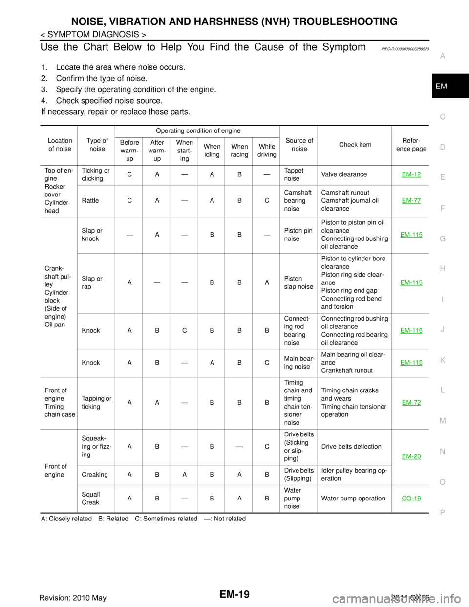
Use the Chart Below to Help You Find the Cause of the SymptomINFOID:0000000006289523
1. Locate the area where noise occurs.
2. Confirm the type of noise.
3. Specify the operating condition of the engine.
4. Check specified noise source.
If necessary, repair or replace these parts.
A: Closely related B: Related C: Sometimes related —: Not related Location
of noise Type of
noise Operating condition of engine
Source of noise Check item Refer-
ence page
Before
warm- up After
warm- up When
start- ing When
idling When
racing While
driving
Top of en-
gine
Rocker
cover
Cylinder
head Ticking or
clicking
CA—AB— Tappet
noiseValve clearance
EM-12
Rattle C A — A B C Camshaft
bearing
noiseCamshaft runout
Camshaft journal oil
clearance
EM-77
Crank-
shaft pul-
ley
Cylinder
block
(Side of
engine)
Oil panSlap or
knock
—A—B B—
Piston pin
noisePiston to piston pin oil
clearance
Connecting rod bushing
oil clearance
EM-115
Slap or
rap
A——B B A
Piston
slap noisePiston to cylinder bore
clearance
Piston ring side clear-
ance
Piston ring end gap
Connecting rod bend
and torsion
EM-115
Knock A B C B B B
Connect-
ing rod
bearing
noiseConnecting rod bushing
oil clearance
Connecting rod bearing
oil clearance
EM-115
Knock A B — A B C
Main bear-
ing noiseMain bearing oil clear-
ance
Crankshaft runout
EM-115
Front of
engine
Timing
chain caseTapping or
ticking
AA—BBB Timing
chain and
timing
chain ten-
sioner
noiseTiming chain cracks
and wears
Timing chain tensioner
operation
EM-72
Front of
engineSqueak-
ing or fizz-
ing
AB—B—C Drive belts
(Sticking
or slip-
ping)Drive belts deflection
EM-20
CreakingABABAB Drive belts
(Slipping)Idler pulley bearing op-
eration
Squall
Creak AB—BAB Water
pump
noiseWater pump operation
CO-19
Revision: 2010 May2011 QX56
Page 2624 of 5598
EM-62
< REMOVAL AND INSTALLATION >
TIMING CHAIN
Removal and Installation
INFOID:0000000006289566
REMOVAL
1. Release fuel pressure. Refer to EC-153, "Work Procedure".
2. Drain engine coolant from radiator. Refer to CO-8, "
Draining".
3. Remove fan shroud (lower). Refer to CO-13, "
Exploded View".
4. Remove fan bracket. Refer to CO-16, "
Exploded View".
5. Remove drive belt auto-tensioner. Refer to EM-26, "
Exploded View".
6. Remove oil level gauge and oil level gauge guide. Refer to EM-57, "
Exploded View".
7. Move power steering oil pump to the posit ion without the hindrance for work. Refer to ST-48, "
Exploded
View".
8. Remove alternator, alternator bracket and alternator stay. Refer to CHG-25, "
Exploded View".
9. Move power steering reservoir tank to the position without the hindrance for work, and then remove Res- ervoir tank bracket. Refer to ST-54, "
Exploded View".
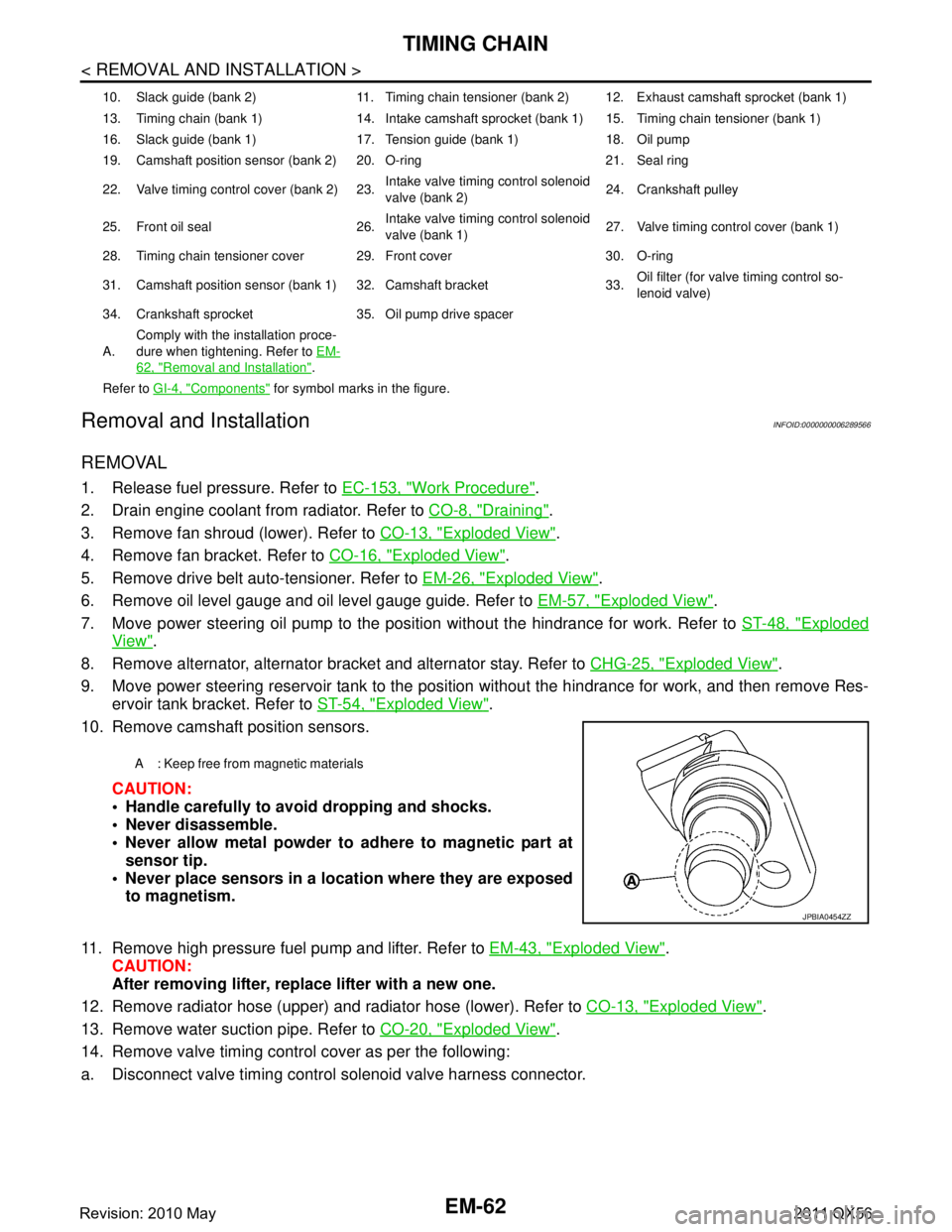
10. Remove camshaft position sensors.
CAUTION:
Handle carefully to avoid dropping and shocks.
Never disassemble.
Never allow metal powder to adhere to magnetic part atsensor tip.
Never place sensors in a lo cation where they are exposed
to magnetism.
11. Remove high pressure fuel pump and lifter. Refer to EM-43, "
Exploded View".
CAUTION:
After removing lifter, replace lifter with a new one.
12. Remove radiator hose (upper) and radiator hose (lower). Refer to CO-13, "
Exploded View".
13. Remove water suction pipe. Refer to CO-20, "
Exploded View".
14. Remove valve timing control cover as per the following:
a. Disconnect valve timing control solenoid valve harness connector.
10. Slack guide (bank 2) 11. Timing chain tensioner (bank 2) 12. Exhaust camshaft sprocket (bank 1)
13. Timing chain (bank 1) 14. Intake camshaft sprocket (bank 1) 15. Timing chain tensioner (bank 1)
16. Slack guide (bank 1) 17. Tension guide (bank 1) 18. Oil pump
19. Camshaft position sensor (bank 2) 20. O-ring 21. Seal ring
22. Valve timing control cover (bank 2) 23. Intake valve timing control solenoid
valve (bank 2)24. Crankshaft pulley
25. Front oil seal 26. Intake valve timing control solenoid
valve (bank 1)27. Valve timing control cover (bank 1)
28. Timing chain tensioner cover 29. Front cover 30. O-ring
31. Camshaft position sensor (bank 1) 32. Camshaft bracket 33. Oil filter (for valve timing control so-
lenoid valve)
34. Crankshaft sprocket 35. Oil pump drive spacer
A. Comply with the installation proce-
dure when tightening. Refer to
EM-
62, "Removal and Installation".
Refer to GI-4, "
Components" for symbol marks in the figure.
A : Keep free from magnetic materials
JPBIA0454ZZ
Revision: 2010 May2011 QX56
Page 2634 of 5598
EM-72
< REMOVAL AND INSTALLATION >
TIMING CHAIN
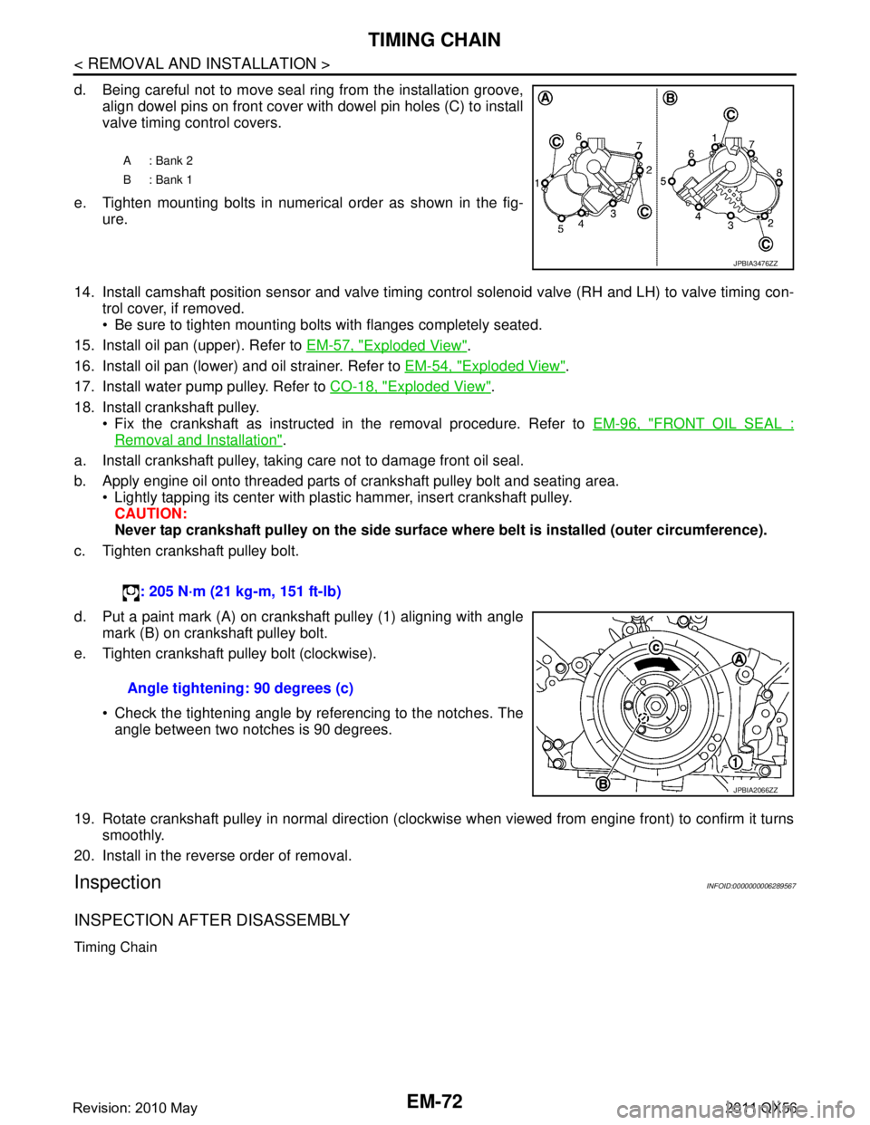
d. Being careful not to move seal ring from the installation groove,align dowel pins on front cover with dowel pin holes (C) to install
valve timing control covers.
e. Tighten mounting bolts in numerical order as shown in the fig- ure.
14. Install camshaft position sensor and valve timing c ontrol solenoid valve (RH and LH) to valve timing con-
trol cover, if removed.
Be sure to tighten mounting bolts with flanges completely seated.
15. Install oil pan (upper). Refer to EM-57, "
Exploded View".
16. Install oil pan (lower) and oil strainer. Refer to EM-54, "
Exploded View".
17. Install water pump pulley. Refer to CO-18, "
Exploded View".
18. Install crankshaft pulley. Fix the crankshaft as instructed in the removal procedure. Refer to EM-96, "
FRONT OIL SEAL :
Removal and Installation".
a. Install crankshaft pulley, taking care not to damage front oil seal.
b. Apply engine oil onto threaded parts of crankshaft pulley bolt and seating area. Lightly tapping its center with plastic hammer, insert crankshaft pulley.
CAUTION:
Never tap crankshaft pulley on the side surface wh ere belt is installed (outer circumference).
c. Tighten crankshaft pulley bolt.
d. Put a paint mark (A) on crankshaft pulley (1) aligning with angle mark (B) on crankshaft pulley bolt.
e. Tighten crankshaft pulley bolt (clockwise).
Check the tightening angle by referencing to the notches. Theangle between two notches is 90 degrees.
19. Rotate crankshaft pulley in normal direction (clockwise when viewed from engine front) to confirm it turns smoothly.
20. Install in the reverse order of removal.
InspectionINFOID:0000000006289567
INSPECTION AFTER DISASSEMBLY
Timing Chain
A: Bank 2
B: Bank 1
JPBIA3476ZZ
: 205 N·m (21 kg-m, 151 ft-lb)
Angle tightening: 90 degrees (c)
JPBIA2066ZZ
Revision: 2010 May2011 QX56
Page 2646 of 5598
EM-84
< REMOVAL AND INSTALLATION >
CAMSHAFT
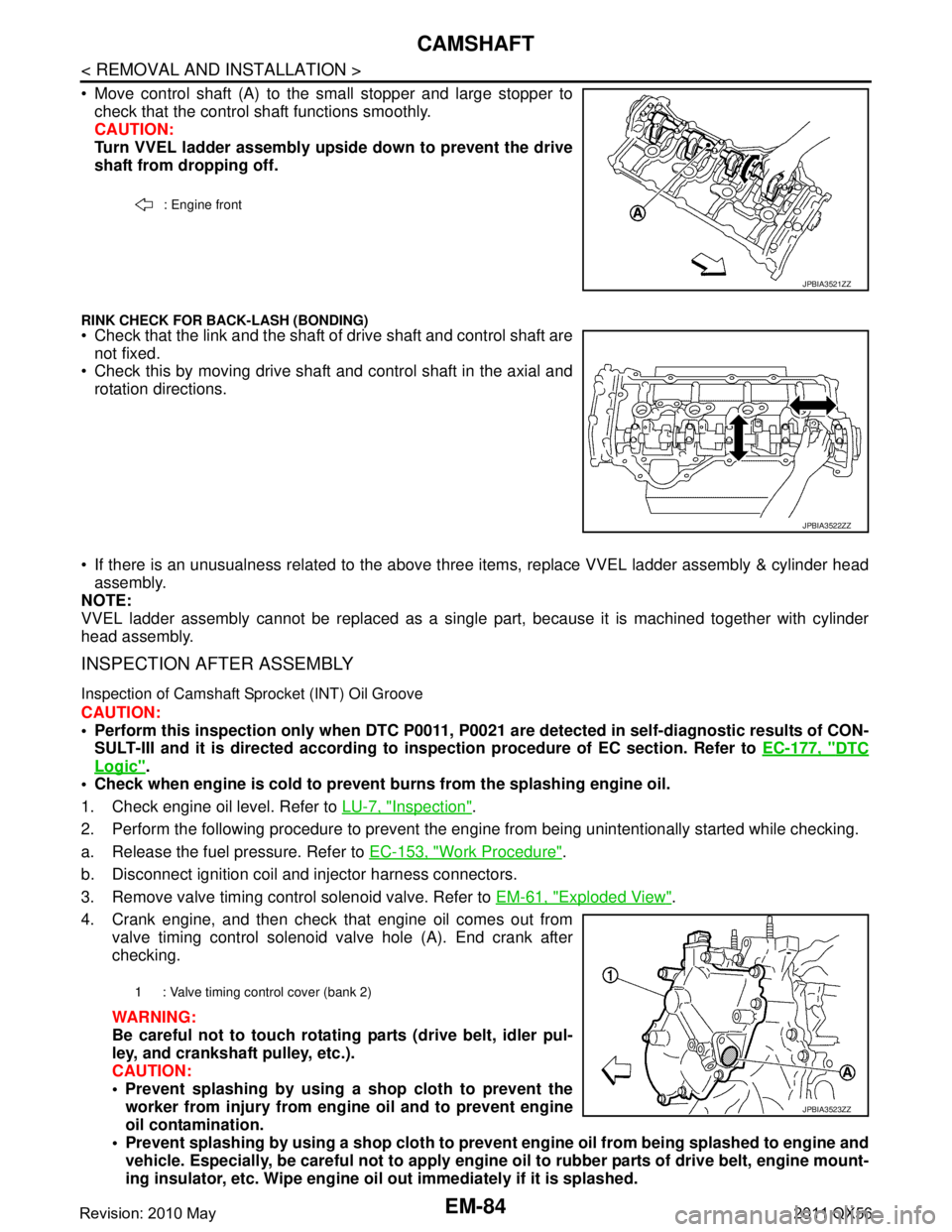
Move control shaft (A) to the small stopper and large stopper tocheck that the control shaft functions smoothly.
CAUTION:
Turn VVEL ladder assembly upside down to prevent the drive
shaft from dropping off.
RINK CHECK FOR BACK-LASH (BONDING) Check that the link and the shaft of drive shaft and control shaft are
not fixed.
Check this by moving drive shaft and control shaft in the axial and
rotation directions.
If there is an unusualness related to the above three items, replace VVEL ladder assembly & cylinder head
assembly.
NOTE:
VVEL ladder assembly cannot be replaced as a singl e part, because it is machined together with cylinder
head assembly.
INSPECTION AFTER ASSEMBLY
Inspection of Camshaft Sprocket (INT) Oil Groove
CAUTION:
Perform this inspection only when DTC P0011, P 0021 are detected in self-diagnostic results of CON-
SULT-III and it is directed according to inspection procedure of EC section. Refer to EC-177, "
DTC
Logic".
Check when engine is cold to prevent burns from the splashing engine oil.
1. Check engine oil level. Refer to LU-7, "
Inspection".
2. Perform the following procedure to prevent the engine from being unintentionally started while checking.
a. Release the fuel pressure. Refer to EC-153, "
Work Procedure".
b. Disconnect ignition coil and injector harness connectors.
3. Remove valve timing control solenoid valve. Refer to EM-61, "
Exploded View".
4. Crank engine, and then check that engine oil comes out from valve timing control solenoid valve hole (A). End crank after
checking.
WARNING:
Be careful not to touch rotati ng parts (drive belt, idler pul-
ley, and crankshaft pulley, etc.).
CAUTION:
Prevent splashing by using a shop cloth to prevent the worker from injury from en gine oil and to prevent engine
oil contamination.
Prevent splashing by using a shop cloth to prevent engine oil from being splashed to engine and
vehicle. Especially, be careful not to apply engine oil to rubber parts of drive belt, engine mount-
ing insulator, etc. Wipe engine oil out immediately if it is splashed.
: Engine front
JPBIA3521ZZ
JPBIA3522ZZ
1 : Valve timing control cover (bank 2)
JPBIA3523ZZ
Revision: 2010 May2011 QX56
Page 2694 of 5598
EM-132
< SERVICE DATA AND SPECIFICATIONS (SDS)
SERVICE DATA AND SPECIFICATIONS (SDS)
SERVICE DATA AND SPECIFICATIONS (SDS)
SERVICE DATA AND SPECIFICATIONS (SDS)
General SpecificationINFOID:0000000006289589
GENERAL SPECIFICATIONS
Drive BeltsINFOID:0000000006289590
DRIVE BELT
Spark PlugINFOID:0000000006289591
SPARK PLUG
Unit: mm (in)
Cylinder arrangementV-8
Displacement cm
3 (cu in) 5,552 (338.80)
Bore and stroke mm (in) 98.0 x 92.0 (3.86 x 3.62)
Valve arrangement DOHC
Firing order 1-8-7-3-6-5-4-2
Number of piston rings Compression 2
Oil 1
Number of main bearings 5
Compression ratio 10.8
Compression pressure
kPa (kg/cm
2, psi)/200 rpm Standard 1,667 (17, 242)
Minimum 1,226 (12.5, 178)
Differential limit between cylinders 98 (1.0, 14)
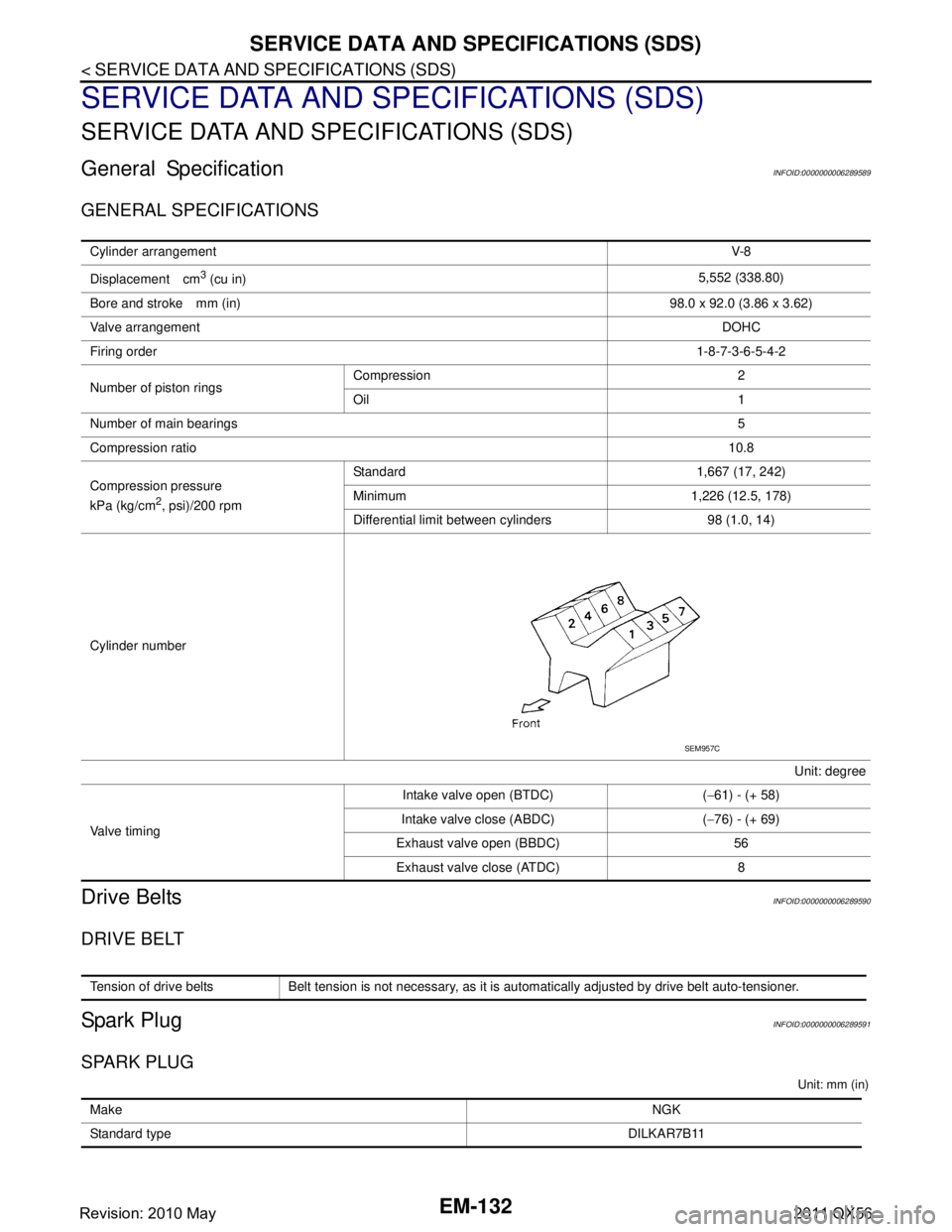
Cylinder number Unit: degree
Valve timing Intake valve open (BTDC) (
−61) - (+ 58)
Intake valve close (ABDC) ( −76) - (+ 69)
Exhaust valve open (BBDC) 56 Exhaust valve close (ATDC) 8
SEM957C
Tension of drive belts Belt tension is not necessary, as it is automatically adjusted by drive belt auto-tensioner.
Make NGK
Standard type DILKAR7B11
Revision: 2010 May2011 QX56
Page 4802 of 5598
COMPONENT PARTSSRC-9
< SYSTEM DESCRIPTION >
C
DE
F
G
I
J
K L
M A
B
SRC
N
O P
Component DescriptionINFOID:0000000006219949
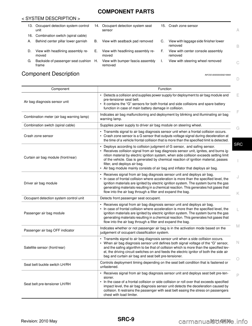
13. Occupant detection system control unit 14. Occupant detection system seat
sensor 15. Crash zone sensor
16. Combination switch (spiral cable)
A. Behind center pillar lower garnish B. View with seatback pad removed C. View with laggage side finisher lower removed
D. View with headlining assembly re- moved E. View with headlining assembly re-
moved F. View with center console assembly
removed
G. Backside of passenger seat cushion frame H. View with bumper fascia assembly
removed I. View with steering wheel removed
Component Function
Air bag diagnosis sensor unit Detects a collision and supplies power supply for deployment to air bag module and
pre-tensioner seat belt.
It contains the “G” sensors for both frontal and side collisions and spare battery function in case of main battery damage in collision.
Combination meter (air bag warning lamp) Indicates air bag malfunctioning and deployment by blinking and illuminating air bag
warning lamp.
Combination switch (spiral cable) Supplies power supply to driver air bag module on steering wheel.
Crash zone sensor Transmits signal to air bag diagnosis sensor unit when a frontal collision occurs.
Crash zone sensor is a G sensor that outputs voltage signal during deceleration at
the time of a vehicle frontal collision that is more than the specified limit is detected.
Curtain air bag module (front/rear) Deploys according to collision judgment of G sensor, and safing sensor.
Receives collision signal from air bag diagnosis sensor unit, ignites, and burns ig-
nition material by electric ignition system, when side collision exceeds setting limit
of the vehicle. Gas is generated by chemical reaction of ignition material, passes
filter, and deploys air bag.
Air bag module mainly consists of air bag and inflator that deploys air bag.
Driver air bag module Receives signal from air bag diagnosis sensor unit and deploys air bag.
In case of frontal collision where acceleration is more than the specified level, the
ignition materials are ignited by electric ignition system. The system burns the gas
generating materials resulting in a chemical reaction. This generates hot gases that
flow into the air bag through a filter and expand the bag.
Occupant detection system control unit Detects front passenger seat occupant.
Passenger air bag module Receives signal from air bag diagnosis sensor unit and deploys air bag.
In case of frontal collision where acceleration is more than the specified level, the
ignition materials are ignited by electric ignition system. The system burns the gas
generating materials resulting in a chemical reaction. This generates hot gases that
flow into the air bag through a filter and expand the bag.
Passenger air bag OFF indicator Indicates whether or not passenger air bag is in the activation mode based on the
judgement of occupant classification system.
Satellite sensor (front/rear) Transmits signal to air bag diagnosis sensor unit when a side collision occurs.
When air bag diagnosis sensor unit defines both signal voltage of the “G” sensor,
and the safing algorithm to be that of collision which is more than the specified lev-
el, the driving circuit switches on and feeds the electric ignitor of both the side air
bag and curtain air bag and seat belt pre-tensioner.
Seat belt buckle switch LH/RH Controls deployment timing depending on the seat belt condition that is fastened or
unfastened.
Seat belt pre-tensioner LH/RH Receives signal from air bag diagnosis sensor unit and deploys seat belt pre-ten-
sioner.
In the case of a frontal collision or side collision or roll over that exceeds specified impact level, the air bag diagnosis sensor unit detects the deceleration caused by
collision. It restrains the passenger with seat belt easing the stress on passengers
chest with load limiter.
Revision: 2010 May2011 QX56