coolant level INFINITI QX56 2011 Factory Owner's Manual
[x] Cancel search | Manufacturer: INFINITI, Model Year: 2011, Model line: QX56, Model: INFINITI QX56 2011Pages: 5598, PDF Size: 94.53 MB
Page 2635 of 5598
TIMING CHAINEM-73
< REMOVAL AND INSTALLATION >
C
DE
F
G H
I
J
K L
M A
EM
NP
O
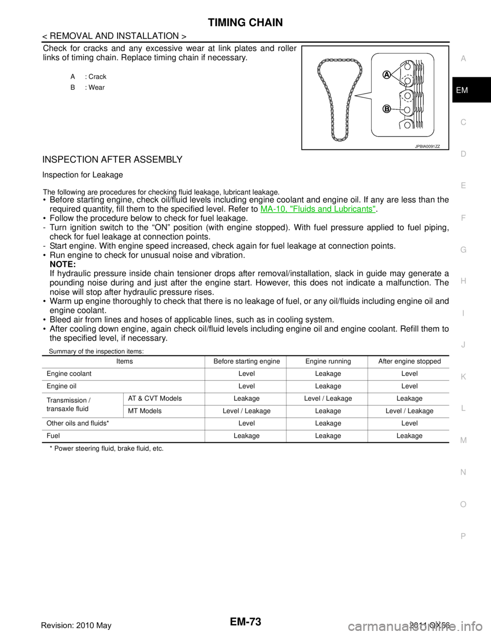
Check for cracks and any excessive
wear at link plates and roller
links of timing chain. Replace timing chain if necessary.
INSPECTION AFTER ASSEMBLY
Inspection for Leakage
The following are procedures for chec king fluid leakage, lubricant leakage. Before starting engine, check oil/fluid levels including engine coolant and engine oil. If any are less than the
required quantity, fill them to the specified level. Refer to MA-10, "
Fluids and Lubricants".
Follow the procedure below to check for fuel leakage.
- Turn ignition switch to the “ON” position (with engi ne stopped). With fuel pressure applied to fuel piping,
check for fuel leakage at connection points.
- Start engine. With engine speed increased, check again for fuel leakage at connection points.
Run engine to check for unusual noise and vibration.
NOTE:
If hydraulic pressure inside chain tensioner drops after removal/installation, slack in guide may generate a
pounding noise during and just after the engine start. However, this does not indicate a malfunction. The
noise will stop after hydraulic pressure rises.
Warm up engine thoroughly to check that there is no leak age of fuel, or any oil/fluids including engine oil and
engine coolant.
Bleed air from lines and hoses of applicable lines, such as in cooling system.
After cooling down engine, again check oil/fluid levels including engine oil and engine coolant. Refill them to the specified level, if necessary.
Summary of the inspection items:
* Power steering fluid, brake fluid, etc. A: Crack
B: Wear
JPBIA0091ZZ
Items Before starting engine Engine running After engine stopped
Engine coolant Level Leakage Level
Engine oil Level Leakage Level
Transmission /
transaxle fluid AT & CVT Models Leakage Level / Leakage Leakage
MT Models Level / Leakage Leakage Level / Leakage
Other oils and fluids* Level Leakage Level
Fuel Leakage Leakage Leakage
Revision: 2010 May2011 QX56
Page 2647 of 5598
CAMSHAFTEM-85
< REMOVAL AND INSTALLATION >
C
DE
F
G H
I
J
K L
M A
EM
NP
O
5. Perform the following inspection if engine oil does not
come out from valve timing control solenoid valve
oil hole of the valve timing control cover.
Remove oil filter, and then clean it. Refer to EM-61, "
Exploded View".
Clean oil groove between oil strainer and valve timing control solenoid valve. Refer to LU-5, "
Engine
Lubrication System" and LU-6, "Engine Lubrication System Schematic".
6. Remove components between valve timing control solenoid valve and camshaft sprocket, and then check each oil groove for clogging.
Clean oil groove if necessary. Refer to LU-5, "
Engine Lubrication System" and LU-6, "Engine Lubrica-
tion System Schematic".
7. After inspection, install removed parts in the reverse order.
Inspection for Leakage
The following are procedures for chec king fluid leakage, lubricant leakage.
Before starting engine, check oil/fluid levels including engine coolant and engine oil. If any are less than the
required quantity, fill them to the specified level. Refer to MA-10, "
Fluids and Lubricants".
Follow the procedure below to check for fuel leakage.
- Turn ignition switch to the “ON” position (with engi ne stopped). With fuel pressure applied to fuel piping,
check for fuel leakage at connection points.
- Start engine. With engine speed increased, check again for fuel leakage at connection points.
Run engine to check for unusual noise and vibration. NOTE:
If hydraulic pressure inside chain tensioner drops after removal/installation, slack in guide may generate a
pounding noise during and just after the engine start. However, this does not indicate a malfunction. The
noise will stop after hydraulic pressure rises.
Warm up engine thoroughly to check that there is no leak age of fuel, or any oil/fluids including engine oil and
engine coolant.
Bleed air from lines and hoses of applicable lines, such as in cooling system.
After cooling down engine, again check oil/fluid levels including engine oil and engine coolant. Refill them to
the specified level, if necessary.
Summary of the inspection items:
* Power steering fluid, brake fluid, etc. Items Before starting engine Engine running After engine stopped
Engine coolant Level Leakage Level
Engine oil Level Leakage Level
Transmission /
transaxle fluid AT & CVT Models Leakage Level / Leakage Leakage
MT Models Level / Leakage Leakage Level / Leakage
Other oils and fluids* Level Leakage Level
Fuel Leakage Leakage Leakage
Revision: 2010 May2011 QX56
Page 2656 of 5598
EM-94
< REMOVAL AND INSTALLATION >
CYLINDER HEAD
Check if the contact area band is continuous all around the circum-ference.
- If not, grind to adjust valve fitting and check again. If the contacting surface still has “NG” conditions even after the re-check, replace
valve seat (EXH). Refer to EM-86, "
Exploded View". (Exhaust
side)
- If not, replace VVEL ladder assembly & cylinder head assembly. Refer to EM-86, "
Exploded View". (Intake side)
NOTE:
Since the valve seat (INT) cannot be replaced by t he piece, VVEL ladder assembly & cylinder head assem-
bly replacement are required.
Valve Spring (with valve spring seat) Squareness
Set a try square (A) along the side of valve spring (with valve
spring seat) and rotate spring. Measure the maximum clearance
between the top of spring and try square.
If it exceeds the limit.
- Replace valve spring (with valve spring seat) (EXH). Refer to EM-
86, "Exploded View". (Exhaust side)
- Replace VVEL ladder assembly & cylinder head assembly. Refer
to EM-86, "
Exploded View". (Intake side)
NOTE:
Since the valve spring (with valve spring seat) (INT) c annot be replaced by the piece, VVEL ladder assembly
& cylinder head assembly replacement are required.
Valve Spring Dimensions and Valve Spring Pressure Load
Check the valve spring (with valve spring seat) pressure at speci- fied spring height.
If the installation load or load with valve open is out of the stan- dard.
- Replace valve spring (with valve spring seat) (EXH). Refer to EM-
86, "Exploded View". (Exhaust side)
- Replace VVEL ladder assembly & cylinder head assembly. Refer to EM-86, "
Exploded View". (Intake side)
NOTE:
Since the valve spring (with valve spring seat) (INT) c annot be replaced by the piece, VVEL ladder assembly
& cylinder head assembly replacement are required.
INSPECTION AFTER ASSEMBLY
Inspection for Leakage
The following are procedures for checking fluid leakage, lubricant leakage.
Before starting engine, check oil/fluid levels includi ng engine coolant and engine oil. If any are less than the
required quantity, fill them to the specified level. Refer to MA-10, "
Fluids and Lubricants".
Follow the procedure below to check for fuel leakage.
- Turn ignition switch to the “ON” position (with engi ne stopped). With fuel pressure applied to fuel piping,
check for fuel leakage at connection points.
- Start engine. With engine speed increased, che ck again for fuel leakage at connection points.
Run engine to check for unusual noise and vibration. NOTE:
A: OK
B: NG
JPBIA0187ZZ
B : Contact
Limit : Refer to EM-135, "CylinderHead".
JPBIA0189ZZ
Standard
: Refer to EM-135, "
CylinderHead".
SEM113
Revision: 2010 May2011 QX56
Page 2657 of 5598

CYLINDER HEADEM-95
< REMOVAL AND INSTALLATION >
C
DE
F
G H
I
J
K L
M A
EM
NP
O
If hydraulic pressure inside chain tensioner drops after removal/installation, slack in guide may generate a
pounding noise during and just after the engine start. However, this does not indicate a malfunction. The
noise will stop after hydraulic pressure rises.
Warm up engine thoroughly to check that there is no leak age of fuel, or any oil/fluids including engine oil and
engine coolant.
Bleed air from lines and hoses of applicable lines, such as in cooling system.
After cooling down engine, again check oil/fluid levels including engine oil and engine coolant. Refill them to
the specified level, if necessary.
Summary of the inspection items:
* Power steering fluid, brake fluid, etc. Items Before starting engine Engine running After engine stopped
Engine coolant Level Leakage Level
Engine oil Level Leakage Level
Transmission /
transaxle fluid AT & CVT Models Leakage Level / Leakage Leakage
MT Models Level / Leakage Leakage Level / Leakage
Other oils and fluids* Level Leakage Level
Fuel Leakage Leakage Leakage
Revision: 2010 May2011 QX56
Page 2664 of 5598
EM-102
< UNIT REMOVAL AND INSTALLATION >
ENGINE ASSEMBLY
INSTALLATION
Install in the reverse order of removal.
CAUTION:
When replacing an engine or transmission you must make sure the dowels are installed correctly
during re-assembly.Improper alignment caused by mi ssing dowels may cause vibration, oil leaks or
breakage of drivetrain components.
InspectionINFOID:0000000006289578
INSPECTION AFTER INSTALLATION
Inspection for Leakage
The following are procedures for checking fluid leakage, lubricant leakage. Before starting engine, check oil/fluid levels includi ng engine coolant and engine oil. If any are less than the
required quantity, fill them to the specified level. Refer to MA-10, "
Fluids and Lubricants".
Follow the procedure below to check for fuel leakage.
- Turn ignition switch to the “ON” position (with engi ne stopped). With fuel pressure applied to fuel piping,
check for fuel leakage at connection points.
- Start engine. With engine speed increased, che ck again for fuel leakage at connection points.
Run engine to check for unusual noise and vibration. NOTE:
If hydraulic pressure inside chain tensioner drops af ter removal/installation, slack in guide may generate a
pounding noise during and just after the engine start. However, this does not indicate a malfunction. The
noise will stop after hydraulic pressure rises.
Warm up engine thoroughly to check that there is no leak age of fuel, or any oil/fluids including engine oil and
engine coolant.
Bleed air from lines and hoses of applic able lines, such as in cooling system.
After cooling down engine, again check oil/fluid levels including engine oil and engine coolant. Refill them to
the specified level, if necessary.
Summary of the inspection items:
*: Power steering fluid, brake fluid, etc. Items Before starting engine Engine running After engine stopped
Engine coolant Level Leakage Level
Engine oil Level Leakage Level
Transmission /
transaxle fluid AT & CVT Models Leakage Level / Leakage Leakage
MT Models Level / Leakage Leakage Level / Leakage
Other oils and fluids* Level Leakage Level
Fuel Leakage Leakage Leakage
Exhaust gases — Leakage —
Revision: 2010 May2011 QX56
Page 2949 of 5598
WHEEL ALIGNMENTFSU-7
< PERIODIC MAINTENANCE >
C
DF
G H
I
J
K L
M A
B
FSU
N
O P
WHEEL ALIGNMENT
InspectionINFOID:0000000006225640
DESCRIPTION
Measure wheel alignment under unladen conditions.
NOTE:
“Unladen conditions” means that fuel, engine coolant, and lubricant are full. Spare tire, jack, hand tools and
mats are in designated positions.
PRELIMINARY CHECK
Check the following:
Tires for improper air pressure and wear
Road wheels for runout: Refer to WT-64, "
Inspection".
Wheel bearing axial end play: Refer to FA X - 7 , "
Inspection" (2WD), FAX-16, "Inspection" (4WD).
Lower link and upper link ball joint axial end play: Refer to FSU-15, "
Inspection" and FSU-18, "Inspection".
Shock absorber operation.
Each mounting part of axle and suspension for looseness and deformation
Lower link for cracks, deformation and other damage
Vehicle height (posture)
GENERAL INFORMATION AND RECOMMENDATIONS
A four-wheel thrust alignment should be performed.
- This type of alignment is recomm ended for any NISSAN/INFINITI vehicle.
- The four-wheel “thrust” process helps ensure that t he vehicle is properly aligned and the steering wheel is
centered.
- The alignment rack itself should be capable of accepting any NISSAN/INFINITI vehicle.
- The rack should be checked to ensure that it is level.
Make sure the machine is properly calibrated.
- Your alignment equipment should be regularly ca librated in order to give correct information.
- Check with the manufacturer of your specific equi pment for their recommended Service/Calibration Sched-
ule.
ALIGNMENT PROCESS
IMPORTANT:
Use only the alignment specificati ons listed in this Service Manual.
When displaying the alignment settings, many alignment machines use “indicators”: (Green/red, plus or
minus, Go/No Go). Never use these indicators.
- The alignment specifications programmed into your machine that operate these indicators may not be cor-
rect.
- This may result in an ERROR.
Some newer alignment machines are equipped with an optional “Rolling Compensation” method to “com-
pensate” the sensors (alignment targets or head units). Never use this “Rolling Compensation” method.
- Use the “Jacking Compensation Method”. After installi ng the alignment targets or head units, raise the vehi-
cle and rotate the wheels 1/2 turn both ways.
- See Instructions in the alignment machine you're using for more information on this.
AdjustmentINFOID:0000000006225641
CAMBER, CASTER
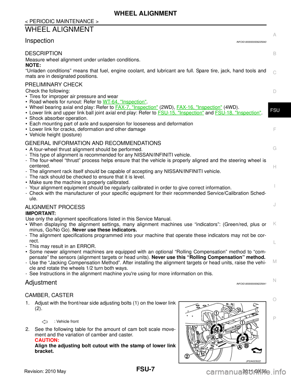
1. Adjust with the front/rear side adjusting bolts (1) on the lower link
(2).
2. See the following table for the amount of cam bolt scale move- ment and the variation of camber and caster.
CAUTION:
Align the adjusting bolt cutout with the stamp of lower link
bracket.
: Vehicle front
JPEIA0235ZZ
Revision: 2010 May2011 QX56
Page 2979 of 5598

ABBREVIATIONSGI-15
< HOW TO USE THIS MANUAL >
C
DE
F
G H
I
J
K L
M B
GI
N
O P
E
F
G
H
ABBREVIATION DESCRIPTION E/T Exhaust temperature
EBD Electric brake force distribution EC Engine control
ECL Engine coolant level
ECM Engine control module ECT Engine coolant temperature
ECV Electrical control valve
EEPROM Electrically erasable programmable read only memory EFT Engine fuel temperature
EGR Exhaust gas recirculation
EGRT Exhaust gas recirculation temperature EGT Exhaust gas temperature
EOP Engine oil pressure EP Exhaust pressure
EPR Exhaust pressure regulator EPS Electronically controlled power steering
ESP Electronic stability program system
EVAP canister Evaporative emission canister EXC Exhaust control
ABBREVIATION DESCRIPTION FC Fan control
FCW Forward collision warning FIC Fuel injector controlFP Fuel pump
FR Front
FRP Fuel rail pressure FRT Fuel rail temperature
FTP Fuel tank pressure FTT Fuel tank temperature
ABBREVIATION DESCRIPTION GND GroundGPS Global positioning systemGST Generic scan tool
ABBREVIATION DESCRIPTION HBMC Hydraulic body-motion control systemHDD Hard disk drive
HO2S Heated oxygen sensor HOC Heated oxidation catalyst
Revision: 2010 May2011 QX56
Page 3121 of 5598
![INFINITI QX56 2011 Factory Owners Manual
SYSTEMHAC-15
< SYSTEM DESCRIPTION > [AUTOMATIC AIR CONDITIONING]
C
D
E
F
G H
J
K L
M A
B
HAC
N
O P
- HAC-17, "FRONT AUTOMATIC AIR CONDITIONING SYSTEM : Air Outlet Control"
-HAC-17, "FRONT AUTOMATIC A INFINITI QX56 2011 Factory Owners Manual
SYSTEMHAC-15
< SYSTEM DESCRIPTION > [AUTOMATIC AIR CONDITIONING]
C
D
E
F
G H
J
K L
M A
B
HAC
N
O P
- HAC-17, "FRONT AUTOMATIC AIR CONDITIONING SYSTEM : Air Outlet Control"
-HAC-17, "FRONT AUTOMATIC A](/img/42/57033/w960_57033-3120.png)
SYSTEMHAC-15
< SYSTEM DESCRIPTION > [AUTOMATIC AIR CONDITIONING]
C
D
E
F
G H
J
K L
M A
B
HAC
N
O P
- HAC-17, "FRONT AUTOMATIC AIR CONDITIONING SYSTEM : Air Outlet Control"
-HAC-17, "FRONT AUTOMATIC AIR CONDITIONIN G SYSTEM : Compressor Control"
-HAC-18, "FRONT AUTOMATIC AIR CONDITION ING SYSTEM : Door Control"
-HAC-21, "FRONT AUTOMATIC AIR CONDITIONIN G SYSTEM : Temperature Control"
- Correction for input value of each sensor
Ambient sensor (setting temperature correction) A/C auto amp. controls passenger room temperature so that the optimum level always matches the temper-
ature level that passenger may feel. Correction is applied to the target temperature that is set using temper-
ature control dial, according to ambient temperature detected by ambient sensor.
Front in-vehicle sensor [in-vehicle temperature (front side) correction]
Passenger room temperature (front side) detected by front in-vehicle sensor is corrected for each front air
conditioning control (driver side and passenger side)
Intake sensor (intake temperature correction)
A/C auto amp. performs correction to change recognition intake temperature of A/C auto amp. quickly when
difference is large between recognition intake temperat ure and intake temperature detected by intake tem-
perature sensor. The correction is performed to change recognition intake temperature slowly when differ-
ence is small.
Sunload sensor (sunload amount correction) Sunload amount detected by sunload sensor is correc ted for each air conditioning control (driver side and
passenger side).
A/C auto amp. performs correction to change recogni tion sunload amount of A/C auto amp. slowly when
sunload amount changes quickly, for exampl e when entering or exiting a tunnel.
Control by ECM
- Cooling fan control
Refer to EC-41, "
COOLING FAN CONTROL : System Description".
- Air conditioning cut control.
Refer to EC-47, "
AIR CONDITIONING CUT CONTRO L : System Description".
Control by IPDM E/R- Relay control
Refer to PCS-5, "
RELAY CONTROL SYSTEM : System Description".
- Cooling fan control
Refer to PCS-8, "
POWER CONTROL SYSTEM : System Description".
Front A/C control (preset switch) transmits the co mmands for front automatic air conditioning system opera-
tion to AV control unit via communication line, then AV control unit transmits the commands to A/C auto amp.
via CAN communication. A/C auto amp. transmits each indication information to AV control unit via CAN
communication. AV control unit displays each indication information that is received.
FRONT AUTOMATIC AIR CONDITIONIN G SYSTEM : Air Flow ControlINFOID:0000000006275862
DESCRIPTION
A/C auto amp. changes duty ratio of blower motor dr ive signal and controls air flow continuously. When air
flow is increased, duty ratio of front blower moto r control signal gradually increases to prevent a sudden
increase in air flow.
In addition to manual control and automatic control, air flow control is consist of starting fan speed control,
low coolant temperature starting control, high in-vehi cle temperature starting control and fan speed control at
door motor operation
AUTOMATIC AIR FLOW CONTROL
A/C auto amp. decides target air flow depending on target front air mix door opening angle.
A/C auto amp. changes duty ratio of front blower moto r control signal and controls the air flow continuously
so that air flow matches to target air flow.
Revision: 2010 May2011 QX56
Page 3130 of 5598
![INFINITI QX56 2011 Factory Owners Manual
HAC-24
< SYSTEM DESCRIPTION >[AUTOMATIC AIR CONDITIONING]
SYSTEM
A/C auto amp. controls passenger r
oom temperature so that the optimum level always matches the temper-
ature level that passenger INFINITI QX56 2011 Factory Owners Manual
HAC-24
< SYSTEM DESCRIPTION >[AUTOMATIC AIR CONDITIONING]
SYSTEM
A/C auto amp. controls passenger r
oom temperature so that the optimum level always matches the temper-
ature level that passenger](/img/42/57033/w960_57033-3129.png)
HAC-24
< SYSTEM DESCRIPTION >[AUTOMATIC AIR CONDITIONING]
SYSTEM
A/C auto amp. controls passenger r
oom temperature so that the optimum level always matches the temper-
ature level that passenger may feel. Correction is applied to the target temperature that is set using temper-
ature control dial, according to ambient temperature detected by ambient sensor.
Rear in-vehicle sensor [in-vehicle temperature (rear side) correction]
Passenger room temperature (rear side) detected by r ear in-vehicle sensor is corrected for each rear auto-
matic air conditioning control.
Intake sensor (intake temperature correction)
A/C auto amp. performs correction to change recogniti on intake temperature of A/C auto amp. quickly when
difference is large between recognition intake temperat ure and intake temperature detected by intake tem-
perature sensor. The correction is performed to change recognition intake temperature slowly when differ-
ence is small.
Sunload sensor (sunload amount correction) Sunload amount detected by sunload sensor is correct ed for each rear automatic air conditioning control.
A/C auto amp. performs correction to change recogni tion sunload amount of A/C auto amp. slowly when
sunload amount changes quickly, for exampl e when entering or exiting a tunnel.
Front control
Operation by front controller
- Front A/C control (preset switch) transmits the co mmands for rear automatic air conditioning system opera-
tion to AV control unit via communication line, then AV control unit transmits the commands to A/C auto amp.
via CAN communication. A/C auto amp. transmits each indication information to AV control unit via CAN
communication. AV control unit displays each indication information that is received.
Operation by rear controller- Rear A/C control transmits the commands for rear automatic air conditioning system operation to A/C auto
amp. via communication line.
REAR AUTOMATIC AIR CONDITIONIN G SYSTEM : Air Flow ControlINFOID:0000000006275871
DESCRIPTION
A/C auto amp. changes duty ratio of blower motor dr ive signal and controls air flow continuously. When air
flow is increased, duty ratio of rear blower moto r control signal gradually increases to prevent a sudden
increase in air flow.
In addition to manual control and automatic control, air flow control is compose of starting fan speed control,
low coolant temperature starting control, high in-vehi cle temperature starting control and fan speed control at
door motor operation
AUTOMATIC AIR FLOW CONTROL
A/C auto amp. decides target air flow depending on target rear air mix door opening angle.
A/C auto amp. changes duty ratio of rear blower moto r control signal and controls the air flow continuously
so that air flow matches to target air flow.
When air outlet is VENT or B/L, the minimum air flow is changed depending on sunload.
STARTING AIR FLOW CONTROL
JMIIA0738GB
Revision: 2010 May2011 QX56
Page 3246 of 5598
![INFINITI QX56 2011 Factory Owners Manual
HAC-140
< SYMPTOM DIAGNOSIS >[AUTOMATIC AIR CONDITIONING]
INSUFFICIENT HEATING
INSUFFICIENT HEATING
FRONT AIR CONDITIONER
FRONT AIR CONDITIONER : DescriptionINFOID:0000000006275990
Symptom Insuffici INFINITI QX56 2011 Factory Owners Manual
HAC-140
< SYMPTOM DIAGNOSIS >[AUTOMATIC AIR CONDITIONING]
INSUFFICIENT HEATING
INSUFFICIENT HEATING
FRONT AIR CONDITIONER
FRONT AIR CONDITIONER : DescriptionINFOID:0000000006275990
Symptom Insuffici](/img/42/57033/w960_57033-3245.png)
HAC-140
< SYMPTOM DIAGNOSIS >[AUTOMATIC AIR CONDITIONING]
INSUFFICIENT HEATING
INSUFFICIENT HEATING
FRONT AIR CONDITIONER
FRONT AIR CONDITIONER : DescriptionINFOID:0000000006275990
Symptom Insufficient heating
No warm air comes out. (Air flow volume is normal.)
FRONT AIR CONDITIONER
: Diagnosis ProcedureINFOID:0000000006275991
NOTE:
Perform self-diagnoses with on board diagnosis and CO NSULT-III before performing symptom diagnosis. If
DTC is detected, perform the corresponding diagnosis.
1.CHECK COOLING SYSTEM
1. Check engine coolant level and check leakage. Refer to CO-8, "
Inspection".
2. Check reservoir tank cap. Refer to CO-11, "
RESERVOIR TANK CAP : Inspection".
3. Check water flow sounds of the engine coolant. Refer to CO-9, "
Refilling".
Is the inspection result normal?
YES >> GO TO 2.
NO >> Refill engine coolant and repair or repl ace parts depending on the inspection results.
2.CHECK HEATER HOSE
Check installation of heater hose by visually or touching.
Is the inspection result normal?
YES >> GO TO 3.
NO >> Repair or replace parts depending on the inspection results.
3.CHECK FRONT HEATER CORE
1. Check temperature of inlet hose and outlet hose of front heater core.
2. Check that inlet side of front heater core is hot and t he outlet side is slightly lower than/almost equal to the
inlet side.
CAUTION:
Always perform the temperature in spection in a short period of time because the engine coolant
temperature is very hot.
Is the inspection result normal?
YES >> GO TO 4.
NO >> Replace front heater core. Refer to HA-44, "
HEATER CORE : Removal and Installation".
4.CHECK AIR LEAKAGE FROM EACH DUCT
Check duct and nozzle, etc. of front air conditioning system for air leakage.
Is the inspection result normal?
YES >> GO TO 5.
NO >> Repair or replace parts depending on the inspection results.
5.CHECK SETTING OF TEMPERATURE SETTING TRIMMER (FRONT)
1. Check setting value of temperature setting trimmer (front). Refer to HAC-68, "
FRONT AUTOMATIC AIR
CONDITIONING SYSTEM : Temperature Setting Trimmer (Front)".
2. Check that temperature setting trimmer (front) is set to “ − direction”.
NOTE:
The control temperature can be set by t he temperature setting trimmer (front).
3. Set difference between the set temperature and control temperature to “0”.
Are the symptoms solved?
YES >> INSPECTION END
NO >> Replace A/C auto amp.. Refer to HAC-146, "
Removal and Installation".
REAR AIR CONDITIONER
Revision: 2010 May2011 QX56