horn INFINITI QX56 2011 Factory Owner's Manual
[x] Cancel search | Manufacturer: INFINITI, Model Year: 2011, Model line: QX56, Model: INFINITI QX56 2011Pages: 5598, PDF Size: 94.53 MB
Page 1720 of 5598

DLK-184
< SYMPTOM DIAGNOSIS >
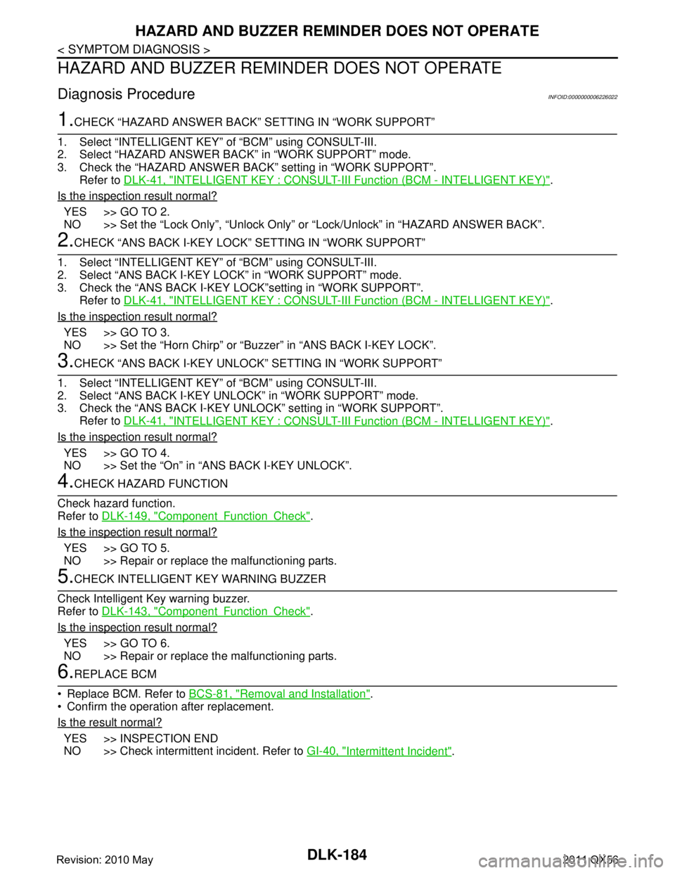
HAZARD AND BUZZER REMINDER DOES NOT OPERATE
HAZARD AND BUZZER REMINDER DOES NOT OPERATE
Diagnosis ProcedureINFOID:0000000006226022
1.CHECK “HAZARD ANSWER BACK” SETTING IN “WORK SUPPORT”
1. Select “INTELLIGE NT KEY” of “BCM” using CONSULT-III.
2. Select “HAZARD ANSWER BACK” in “WORK SUPPORT” mode.
3. Check the “HAZARD ANSWER BACK ” setting in “WORK SUPPORT”.
Refer to DLK-41, "
INTELLIGENT KEY : CONSULT-III F unction (BCM - INTELLIGENT KEY)".
Is the inspection result normal?
YES >> GO TO 2.
NO >> Set the “Lock Only”, “Unlock Only” or “Lock/Unlock” in “HAZARD ANSWER BACK”.
2.CHECK “ANS BACK I-KEY LOCK” SETTING IN “WORK SUPPORT”
1. Select “INTELLIGE NT KEY” of “BCM” using CONSULT-III.
2. Select “ANS BACK I-KEY LO CK” in “WORK SUPPORT” mode.
3. Check the “ANS BACK I-KEY LOCK”setting in “WORK SUPPORT”. Refer to DLK-41, "
INTELLIGENT KEY : CONSULT-III F unction (BCM - INTELLIGENT KEY)".
Is the inspection result normal?
YES >> GO TO 3.
NO >> Set the “Horn Chirp” or “Bu zzer” in “ANS BACK I-KEY LOCK”.
3.CHECK “ANS BACK I-KEY UNLOCK” SETTING IN “WORK SUPPORT”
1. Select “INTELLIGE NT KEY” of “BCM” using CONSULT-III.
2. Select “ANS BACK I-KEY UNL OCK” in “WORK SUPPORT” mode.
3. Check the “ANS BACK I-KEY UNLOCK” setting in “WORK SUPPORT”.
Refer to DLK-41, "
INTELLIGENT KEY : CONSULT-III F unction (BCM - INTELLIGENT KEY)".
Is the inspection result normal?
YES >> GO TO 4.
NO >> Set the “On” in “ANS BACK I-KEY UNLOCK”.
4.CHECK HAZARD FUNCTION
Check hazard function.
Refer to DLK-149, "
ComponentFunctionCheck".
Is the inspection result normal?
YES >> GO TO 5.
NO >> Repair or replace the malfunctioning parts.
5.CHECK INTELLIGENT KEY WARNING BUZZER
Check Intelligent Key warning buzzer.
Refer to DLK-143, "
ComponentFunctionCheck".
Is the inspection result normal?
YES >> GO TO 6.
NO >> Repair or replace the malfunctioning parts.
6.REPLACE BCM
Replace BCM. Refer to BCS-81, "
Removal and Installation".
Confirm the operation after replacement.
Is the result normal?
YES >> INSPECTION END
NO >> Check intermittent incident. Refer to GI-40, "
Intermittent Incident".
Revision: 2010 May2011 QX56
Page 1740 of 5598

DLK-204
< SYMPTOM DIAGNOSIS >
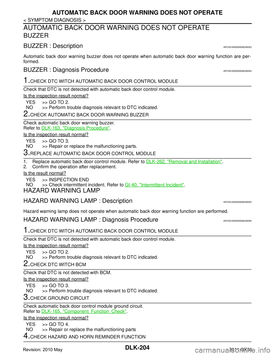
AUTOMATIC BACK DOOR WARNING DOES NOT OPERATE
AUTOMATIC BACK DOOR WARNING DOES NOT OPERATE
BUZZER
BUZZER : DescriptionINFOID:0000000006226053
Automatic back door warning buzzer does not operate when automatic back door warning function are per-
formed.
BUZZER : Diagnosis ProcedureINFOID:0000000006226054
1.CHECK DTC WITCH AUTOMATIC BACK DOOR CONTROL MODULE
Check that DTC is not detected with automatic back door control module.
Is the inspection result normal?
YES >> GO TO 2.
NO >> Perform trouble diagnosis relevant to DTC indicated.
2.CHECK AUTOMATIC BACK DOOR WARNING BUZZER
Check automatic back door warning buzzer.
Refer to DLK-163, "
Diagnosis Procedure".
Is the inspection result normal?
YES >> GO TO 3.
NO >> Repair or replace the malfunctioning parts.
3.REPLACE AUTOMATIC BACK DOOR CONTROL MODULE
1. Replace automatic back door control module. Refer to DLK-262, "
Removal and Installation".
2. Confirm the operation after replacement.
Is the result normal?
YES >> INSPECTION END
NO >> Check intermittent incident. Refer to GI-40, "
Intermittent Incident".
HAZARD WARNING LAMP
HAZARD WARNING LAMP : DescriptionINFOID:0000000006226055
Hazard warning lamp does not operate when automatic back door warning function are performed.
HAZARD WARNING LAMP : Diagnosis ProcedureINFOID:0000000006226056
1.CHECK DTC WITCH AUTOMATIC BACK DOOR CONTROL MODULE
Check that DTC is not detected with automatic back door control module.
Is the inspection result normal?
YES >> GO TO 2.
NO >> Perform trouble diagnosis relevant to DTC indicated.
2.CHECK DTC WITCH BCM
Check that DTC is not detected with BCM.
Is the inspection result normal?
YES >> GO TO 3.
NO >> Perform trouble diagnosis relevant to DTC indicated.
3.CHECK GROUND CIRCUIT
Check automatic back door control module ground circuit.
Refer to DLK-165, "
ComponentFunctionCheck".
Is the inspection result normal?
YES >> GO TO 4.
NO >> Repair or replace the malfunctioning parts
4.CHECK HAZARD AND HORN REMINDER FUNCTION
Revision: 2010 May2011 QX56
Page 1741 of 5598

AUTOMATIC BACK DOOR WARNING DOES NOT OPERATE
DLK-205
< SYMPTOM DIAGNOSIS >
C
D E
F
G H
I
J
L
M A
B
DLK
N
O P
Check hazard and horn reminder function.
Is the inspection result normal?
YES >> GO TO 5.
NO >> Refer to DLK-183, "
Diagnosis Procedure".
5.REPLACE AUTOMATIC BACK DOOR CONTROL MODULE
1. Replace automatic back door control module. Refer to DLK-262, "
Removal and Installation".
2. Confirm the operation after replacement.
Is the result normal?
YES >> INSPECTION END
NO >> Check intermittent incident. Refer to GI-40, "
Intermittent Incident".
Revision: 2010 May2011 QX56
Page 1756 of 5598

DLK-220
< REMOVAL AND INSTALLATION >
RADIATOR CORE SUPPORT
RADIATOR CORE SUPPORT
Exploded ViewINFOID:0000000006226068
Removal and InstallationINFOID:0000000006226069
RADIATOR CORE SUPPORT UPPER
Removal
CAUTION:
When removing radiator core support upper, be careful not to damage the painted surface.
1. Remove bumper molding, bumper molding stay LH and RH. Refer to EXT-13, "
Removal and Installation".
2. Remove fixing clips, and then radiator upper seal.
3. Remove horn (LOW and HIGH). Refer to HRN-6, "
Removal and Installation".
4. Remove exhaust gas / outside oder sensor. Refer to HAC-151, "
Removal and Installation".
5. Disconnect refrigerant pressu re sensor harness connector.
1. Radiator upper seal 2. Radiator core support upper 3. Air guide seal LH
4. Air guide seal RH 5. Radiator side seal RH 6. Radiator lower seal RH
7. Radiator lower seal LH 8. Radiator side seal LH 9. Radiator core support main
Refer to for symbols in the figure.GI-4, "
Components"
JMKIA5479GB
Revision: 2010 May2011 QX56
Page 2737 of 5598
![INFINITI QX56 2011 Factory Owners Manual
DIAGNOSIS SYSTEM (IPDM E/R)EXL-27
< SYSTEM DESCRIPTION > [XENON TYPE]
C
D
E
F
G H
I
J
K
M A
B
EXL
N
O P
DIAGNOSIS SYSTEM (IPDM E/R)
Diagnosis DescriptionINFOID:0000000006368066
AUTO ACTIVE TEST
Descr INFINITI QX56 2011 Factory Owners Manual
DIAGNOSIS SYSTEM (IPDM E/R)EXL-27
< SYSTEM DESCRIPTION > [XENON TYPE]
C
D
E
F
G H
I
J
K
M A
B
EXL
N
O P
DIAGNOSIS SYSTEM (IPDM E/R)
Diagnosis DescriptionINFOID:0000000006368066
AUTO ACTIVE TEST
Descr](/img/42/57033/w960_57033-2736.png)
DIAGNOSIS SYSTEM (IPDM E/R)EXL-27
< SYSTEM DESCRIPTION > [XENON TYPE]
C
D
E
F
G H
I
J
K
M A
B
EXL
N
O P
DIAGNOSIS SYSTEM (IPDM E/R)
Diagnosis DescriptionINFOID:0000000006368066
AUTO ACTIVE TEST
Description
In auto active test, the IPDM E/R sends a drive signal to the following systems to check their operation.
Oil pressure warning lamp
Rear window defogger
Front wiper (LO, HI)
Parking lamp
License plate lamp
Tail lamp
Side marker lamp
Front fog lamp
Headlamp (LO, HI)
A/C compressor (magnet clutch)
Operation Procedure
CAUTION:
Never perform auto active test in the following conditions.
Engine is running.
CONSULT-III is connected.
1. Close the hood and lift the wiper arms from the windshield. (Prevent windshield damage due to wiper
operation)
NOTE:
When auto active test is performed with hood opened, sprinkle water on windshield beforehand.
2. Turn the ignition switch OFF.
3. Turn the ignition switch ON, and within 20 seconds, pr ess the driver door switch 10 times. Then turn the
ignition switch OFF.
CAUTION:
Close passenger door.
4. Turn the ignition switch ON within 10 seconds. Af ter that the horn sounds once and the auto active test
starts.
CAUTION:
Engine starts when ignition switch is turned ON while brake pedal is depressed.
5. The oil pressure warning lamp starts blinking when the auto active test starts.
6. After a series of the following operations is repeated 3 times, auto active test is completed.
NOTE:
When auto active test has to be cancelled halfw ay through test, turn the ignition switch OFF.
When auto active test is not activated, door swit ch may be the cause. Check door switch. Refer to DLK-117,
"ComponentFunctionCheck".
Inspection in Auto Active Test
When auto active test is actuated, the following operation sequence is repeated 3 times.
Operation
sequence Inspection location Operation
1 Oil pressure warning lamp Blinks continuously during operation of auto active test
2 Rear window defogger 10 seconds
3 Front wiper LO for 5 seconds → HI for 5 seconds
4 Parking lamp
License plate lamp
Tail lamp
Side marker lamp
Front fog lamp 10 seconds
Revision: 2010 May2011 QX56
Page 2740 of 5598
![INFINITI QX56 2011 Factory Owners Manual
EXL-30
< SYSTEM DESCRIPTION >[XENON TYPE]
DIAGNOSIS SYSTEM (IPDM E/R)
ACTIVE TEST
Te s t i t e m
PUSH SW
[Off/On]Displays the status of the push-button ignition switch judged by IPDM E/R.
INTER/NP S INFINITI QX56 2011 Factory Owners Manual
EXL-30
< SYSTEM DESCRIPTION >[XENON TYPE]
DIAGNOSIS SYSTEM (IPDM E/R)
ACTIVE TEST
Te s t i t e m
PUSH SW
[Off/On]Displays the status of the push-button ignition switch judged by IPDM E/R.
INTER/NP S](/img/42/57033/w960_57033-2739.png)
EXL-30
< SYSTEM DESCRIPTION >[XENON TYPE]
DIAGNOSIS SYSTEM (IPDM E/R)
ACTIVE TEST
Te s t i t e m
PUSH SW
[Off/On]Displays the status of the push-button ignition switch judged by IPDM E/R.
INTER/NP SW
[Off/On] Displays the status of the shift position judged by IPDM E/R.
ST RLY CONT
[Off/On] Displays the status of the starter relay status signal received from BCM via CAN
communication.
IHBT RLY -REQ
[Off/On] Displays the status of the starter control relay signal received from BCM via CAN
communication.
ST/INHI RLY
[Off/ ST ON/INHI ON/UNKWN] Displays the status of the starter relay and starter control relay judged by IPDM
E/R.
DETENT SW
[Off/On] Displays the status of the A/T shift selector (detention switch) judged by IPDM E/
R.
S/L RLY -REQ
[Off/On] Displays the status of the steering lock relay signal received from BCM via CAN
communication.
S/L STATE
[LOCK/UNLK/UNKWN] Displays the status of the steering lock judged by IPDM E/R.
OIL P SW
[Open/Close] Displays the status of the oil pressure switch judged by IPDM E/R.
HOOD SW
[Off/On] Displays the status of the hood switch judged by IPDM E/R.
HL WASHER REQ
[Off/On] Displays the status of the headlamp washer request signal received from BCM via
CAN communication.
THFT HRN REQ
[Off/On] Displays the status of the theft warning horn request signal received from BCM
via CAN communication.
HORN CHIRP
[Off/On] Displays the status of the horn reminder signal received from BCM via CAN com-
munication.
Monitor Item
[Unit] MAIN SIG-
NALS Description
Test item Operation Description
CORNERING LAMP LH
NOTE:
This item is indicated, but cannot be tested.
RH
HORN On Operates horn relay for 20 ms.
REAR DEFOGGER Off OFF
On Operates the rear window defogger relay.
FRONT WIPER Off OFF
Lo Operates the front wiper relay.
Hi Operates the front wiper relay and front wiper high relay.
MOTOR FAN* 1OFF
2 Transmits 50% pulse duty signal (PWM signal) to the cooling fan control module.
3 Transmits 75% pulse duty signal (PWM signal) to the cooling fan control module.
4
Transmits 100% pulse duty signal (PWM signal) to the cooling fan control mod-
ule.
HEAD LAMP WASHER On Operates the headlamp washer relay for 1 second.
Revision: 2010 May2011 QX56
Page 3262 of 5598

HRN-1
DRIVER CONTROLS
C
DE
F
G H
I
J
K
M
SECTION HRN
A
B
HRN
N
O P
CONTENTS
HORN
PRECAUTION ................ ...............................2
PRECAUTIONS .............................................. .....2
Precaution for Supplemental Restraint System
(SRS) "AIR BAG" and "SEAT BELT PRE-TEN-
SIONER" ............................................................. ......
2
WIRING DIAGRAM .......................................3
HORN .................................................................3
Wiring Diagram .................................................... .....3
REMOVAL AND INSTALLATION ................6
HORN .................................................................6
Exploded View ..................................................... .....6
Removal and Installation ..........................................6
Revision: 2010 May2011 QX56
Page 3264 of 5598

HORN
HRN-3
< WIRING DIAGRAM >
C
D E
F
G H
I
J
K
M A
B
HRN
N
O P
WIRING DIAGRAM
HORN
Wiring DiagramINFOID:0000000006220274
JCLWM5295GB
Revision: 2010 May2011 QX56
Page 3265 of 5598

HRN-4
< WIRING DIAGRAM >
HORN
JCLWM5508GB
Revision: 2010 May2011 QX56
Page 3266 of 5598

HORN
HRN-5
< WIRING DIAGRAM >
C
D E
F
G H
I
J
K
M A
B
HRN
N
O P
JCLWM5509GB
Revision: 2010 May2011 QX56