Starter INFINITI QX56 2011 Factory Repair Manual
[x] Cancel search | Manufacturer: INFINITI, Model Year: 2011, Model line: QX56, Model: INFINITI QX56 2011Pages: 5598, PDF Size: 94.53 MB
Page 5073 of 5598

COMPONENT PARTSSTR-5
< SYSTEM DESCRIPTION >
C
DE
F
G H
I
J
K L
M A
STR
NP
O
SYSTEM DESCRIPTION
COMPONENT PARTS
Component Parts LocationINFOID:0000000006275518
Component DescriptionINFOID:0000000006275519
1. IPDM E/R
Refer to PCS-4, "
Component Parts
Location". 2. Starter motor 3. TCM
Refer to TM-10, "
A/T CONTROL SYS-
TEM : Component Parts Location".
4. BCM Refer to BCS-4, "
BODY CONTROL
SYSTEM : Componen t Parts Loca-
tion".
A. Engine
JMBIA2982ZZ
Component part Description
BCM BCM controls the starter relay inside IPDM E/R.
IPDM E/R CPU inside IPDM E/R controls the starter control relay.
Starter motor The starter motor plunger closes and the motor is supplied with battery power, which in
turn cranks the engine, when the “S” terminal is supplied with electric power.
TCM TCM supplies power to the starter relay and starter control relay inside IPDM E/R when
the selector lever is shifted to the P or N position.
Revision: 2010 May2011 QX56
Page 5074 of 5598

STR-6
< SYSTEM DESCRIPTION >
SYSTEM
SYSTEM
System DiagramINFOID:0000000006275520
System DescriptionINFOID:0000000006275521
When selector lever is P or N, power is supplied to starter relay and starter control relay by TCM. And BCM
and IPDM E/R (CPU) detect selector lever P/N condition by the inputted signal.
When starter operating condition is satisfied, IPDM E/R tu rns starter control relay ON by starter control relay
control signal.
When engine cranking condition is satisfied, BCM turns starter relay ON by starter relay control signal.
Then battery power is supplied to starter motor (“S” terminal) through starter control relay and starter relay. And IPDM E/R (CPU) detect starter re lay condition by the inputted signal.
JMBIA2983GB
Revision: 2010 May2011 QX56
Page 5080 of 5598

STR-12
< BASIC INSPECTION >
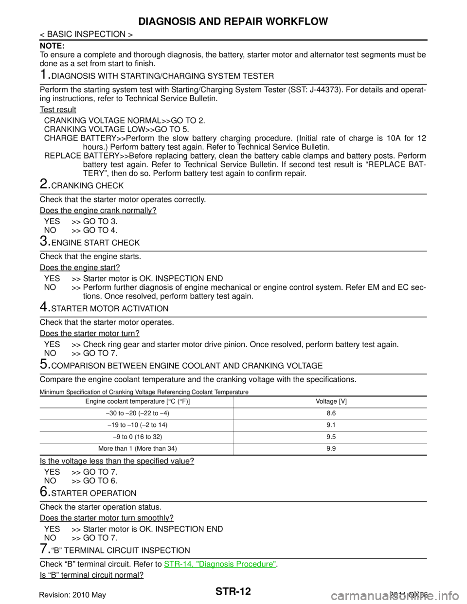
DIAGNOSIS AND REPAIR WORKFLOW
NOTE:
To ensure a complete and thorough diagnosis, the battery, starter motor and alternator test segments must be
done as a set from start to finish.
1.DIAGNOSIS WITH STARTING /CHARGING SYSTEM TESTER
Perform the starting system test with Starting/Char ging System Tester (SST: J-44373). For details and operat-
ing instructions, refer to Technical Service Bulletin.
Te s t r e s u l t
CRANKING VOLTAGE NORMAL>>GO TO 2.
CRANKING VOLTAGE LOW>>GO TO 5.
CHARGE BATTERY>>Perform the slow battery charging procedure. (Initial rate of charge is 10A for 12
hours.) Perform battery test again. Re fer to Technical Service Bulletin.
REPLACE BATTERY>>Before replacing battery, clean t he battery cable clamps and battery posts. Perform
battery test again. Refer to Technical Service Bu lletin. If second test result is “REPLACE BAT-
TERY”, then do so. Perform battery test again to confirm repair.
2.CRANKING CHECK
Check that the starter motor operates correctly.
Does the engine crank normally?
YES >> GO TO 3.
NO >> GO TO 4.
3.ENGINE START CHECK
Check that the engine starts.
Does the engine start?
YES >> Starter motor is OK. INSPECTION END
NO >> Perform further diagnosis of engine mechanical or engine control system. Refer EM and EC sec-
tions. Once resolved, perform battery test again.
4.STARTER MOTOR ACTIVATION
Check that the starter motor operates.
Does the starter motor turn?
YES >> Check ring gear and starter motor drive pinion. Once resolved, perform battery test again.
NO >> GO TO 7.
5.COMPARISON BETWEEN ENGINE COOLANT AND CRANKING VOLTAGE
Compare the engine coolant temperature and the cranking voltage with the specifications.
Minimum Specification of Cranking Voltage Referencing Coolant Temperature
Is the voltage less than the specified value?
YES >> GO TO 7.
NO >> GO TO 6.
6.STARTER OPERATION
Check the starter operation status.
Does the starter motor turn smoothly?
YES >> Starter motor is OK. INSPECTION END
NO >> GO TO 7.
7.“B” TERMINAL CIRCUIT INSPECTION
Check “B” terminal circuit. Refer to STR-14, "
Diagnosis Procedure".
Is
“B” terminal circuit normal?
Engine coolant temperature [ °C ( °F)] Voltage [V]
− 30 to −20 ( −22 to −4) 8.6
− 19 to −10 ( −2 to 14) 9.1
− 9 to 0 (16 to 32) 9.5
More than 1 (More than 34) 9.9
Revision: 2010 May2011 QX56
Page 5081 of 5598

DIAGNOSIS AND REPAIR WORKFLOWSTR-13
< BASIC INSPECTION >
C
DE
F
G H
I
J
K L
M A
STR
NP
O
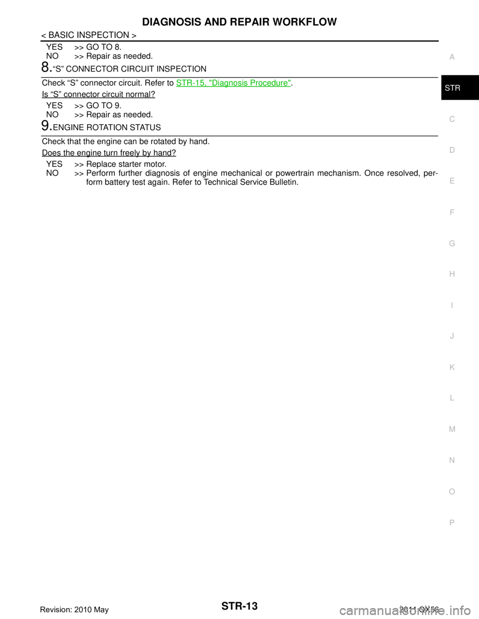
YES >> GO TO 8.
NO >> Repair as needed.
8.“S” CONNECTOR CIRCUIT INSPECTION
Check “S” connector circuit. Refer to STR-15, "
Diagnosis Procedure".
Is
“S” connector circuit normal?
YES >> GO TO 9.
NO >> Repair as needed.
9.ENGINE ROTATION STATUS
Check that the engine can be rotated by hand.
Does the engine turn freely by hand?
YES >> Replace starter motor.
NO >> Perform further diagnosis of engine mechanical or powertrain mechanism. Once resolved, per-
form battery test again. Refer to Technical Service Bulletin.
Revision: 2010 May2011 QX56
Page 5082 of 5598

STR-14
< DTC/CIRCUIT DIAGNOSIS >
B TERMINAL CIRCUIT
DTC/CIRCUIT DIAGNOSIS
B TERMINAL CIRCUIT
Diagnosis ProcedureINFOID:0000000006275524
CAUTION:
Perform diagnosis under the condition that engine cannot start by the following procedure.
1. Remove fuel pump fuse.
2. Crank or start the engine (where possi ble) until the fuel pressure is released.
1.CHECK “B” TERMINAL CIRCUIT
1. Turn ignition switch OFF.
2. Check that starter motor “B” terminal connection is clean and tight.
3. Check voltage between starter motor “B” terminal and ground.
Is the inspection result normal?
YES >> GO TO 2.
NO >> Check harness between battery and starter motor for open circuit.
2.CHECK BATTERY CABLE CONNECTION STATUS (VOLTAGE DROP TEST)
1. Shift A/T selector lever to “P” or “N” position.
2. Check voltage between battery positive terminal and starter motor “B” terminal.
Is the inspection result normal?
YES >> GO TO 3.
NO >> Check harness between the battery and the starter motor for poor continuity.
3.CHECK GROUND CIRCUIT STATUS (VOLTAGE DROP TEST)
1. Shift A/T selector lever to “P” or “N” position.
2. Check voltage between starter motor case and battery negative terminal.
Is the inspection result normal?
YES >> “B” terminal circuit is OK. Further inspection is necessary. Refer to STR-11, "Work Flow".
NO >> Check the starter motor case and ground for poor continuity.
(+) (–) Voltage
Starter motor “B” terminal
F57 2 Ground Battery voltage
(+) (–)
ConditionVoltage (V)
(Approx.)
Starter motor “B” terminal
Battery positive terminal F57 2 When the ignition switch
is in START position Less than 0.5
(+) (–) Condition Voltage (V)
(Approx.)
Starter motor case Battery negative terminal When the ignition switch is in START position Less than 0.2
Revision: 2010 May2011 QX56
Page 5083 of 5598

S CONNECTOR CIRCUITSTR-15
< DTC/CIRCUIT DIAGNOSIS >
C
DE
F
G H
I
J
K L
M A
STR
NP
O
S CONNECTOR CIRCUIT
Diagnosis ProcedureINFOID:0000000006275525
CAUTION:
Perform diagnosis under the cond
ition that engine cannot start by the following procedure.
1. Remove fuel pump fuse.
2. Crank or start the engine (where possi ble) until the fuel pressure is released.
1.CHECK “S” CONNECTOR CIRCUIT
1. Turn ignition switch OFF.
2. Disconnect starter motor connector.
3. Shift A/T selector lever to “P” or “N” position.
4. Check voltage between starter motor harness connector and ground.
Is the inspection result normal?
YES >> “S” connector circuit is OK. Furt her inspection is necessary. Refer to STR-11, "Work Flow".
NO >> GO TO 2.
2.CHECK HARNESS CONTI NUITY (OPEN CIRCUIT)
1. Turn ignition switch OFF.
2. Disconnect IPDM E/R harness connector.
3. Check continuity between starter motor harness connector and IPDM E/R harness connector.
Is the inspection result normal?
YES >> Further inspection is necessary. Refer to SEC-48, "Work Flow".
NO >> Repair the harness or connector.
(+)
(–) Condition Voltage
Starter motor
Connector Terminal
F55 1 Ground When the ignition switch
is in START position Battery voltage
Starter motor harness IPDM E/R
Continuity
Connector Terminal Connector Terminal
F55 1 E10 3 Existed
Revision: 2010 May2011 QX56
Page 5084 of 5598

STR-16
< SYMPTOM DIAGNOSIS >
STARTING SYSTEM
SYMPTOM DIAGNOSIS
STARTING SYSTEM
Symptom TableINFOID:0000000006275526
Symptom Reference
No normal cranking Refer to STR-11, "
Work Flow".
Starter motor does not rotate
Revision: 2010 May2011 QX56
Page 5085 of 5598

STARTER MOTORSTR-17
< REMOVAL AND INSTALLATION >
C
DE
F
G H
I
J
K L
M A
STR
NP
O
REMOVAL AND INSTALLATION
STARTER MOTOR
Exploded ViewINFOID:0000000006275527
REMOVAL
DISASSEMBLY
1. Starter motor 2. “S” connector 3. “B” terminal harness
4. “B” terminal nut 5. Starter motor mounting bolt 6. Cylinder block
: Engine front
Refer to GI-4, "
Components" for symbols in the figure.
JMBIA2970GB
Revision: 2010 May2011 QX56
Page 5086 of 5598

STR-18
< REMOVAL AND INSTALLATION >
STARTER MOTOR
Type: M001T30671
Removal and InstallationINFOID:0000000006275528
REMOVAL
1. Disconnect the battery cable from the negative terminal. Refer to PG-164, "Removal and Installation".
2. Remove engine cover. Refer to EM-25, "
Removal and Installation".
3. Remove intake manifold. Refer to EM-30, "
Removal and Installation".
4. Remove “B” terminal nut, and then “B” terminal harness.
5. Remove harness clip of “S ” connector from heater pipe.
6. Disconnect “S” connector.
7. Remove starter motor mounting bolts.
8. Remove starter motor upward from the vehicle.
INSTALLATION
Note the following item, and then install in the reverse order of removal.
CAUTION:
Be careful to tighten “B” terminal nut carefully.
InspectionINFOID:0000000006275534
INSPECTION AFTER DISASSEMBLY
JPBIA2426GB
1. Magnetic switch assembly 2. Adjusting plate 3. “B” terminal extension
4. Gear case assembly 5. Stopper ring 6. Stopper
7. Pinion assembly 8. Internal gear 9. Yoke assembly
10. Armature assembly 11. Brush holder assembly 12. Metal RR
13. Rear cover 14. Through bolt 15. Packing
16. Ball 17. Planetary gear 18. Gear shaft
19. Dust cover kit 20. Shift lever
: High-temperature grease point
Refer to GI-4, "
Components" for symbols not described on the above.
Revision: 2010 May2011 QX56
Page 5087 of 5598

STARTER MOTORSTR-19
< REMOVAL AND INSTALLATION >
C
DE
F
G H
I
J
K L
M A
STR
NP
O
Pinion/Clutch Check
1. Inspect pinion teeth.
Replace pinion if teeth are worn or damaged. (Also check condition of ring gear teeth.)
2. Inspect reduction gear teeth. Replace reduction gear if teeth are worn or dam aged. (Also check condition of armature shaft gear
teeth.)
3. Check to see if pinion locks in one directi on and rotates smoothly in the opposite direction.
If it locks or rotates in both directions, or unusual resistance is evident, replace.
Revision: 2010 May2011 QX56