wheel INFINITI QX56 2011 Factory Service Manual
[x] Cancel search | Manufacturer: INFINITI, Model Year: 2011, Model line: QX56, Model: INFINITI QX56 2011Pages: 5598, PDF Size: 94.53 MB
Page 1 of 5598
A
B
D
E
F
G
H
I
J
K
L
M
N
P
O
C
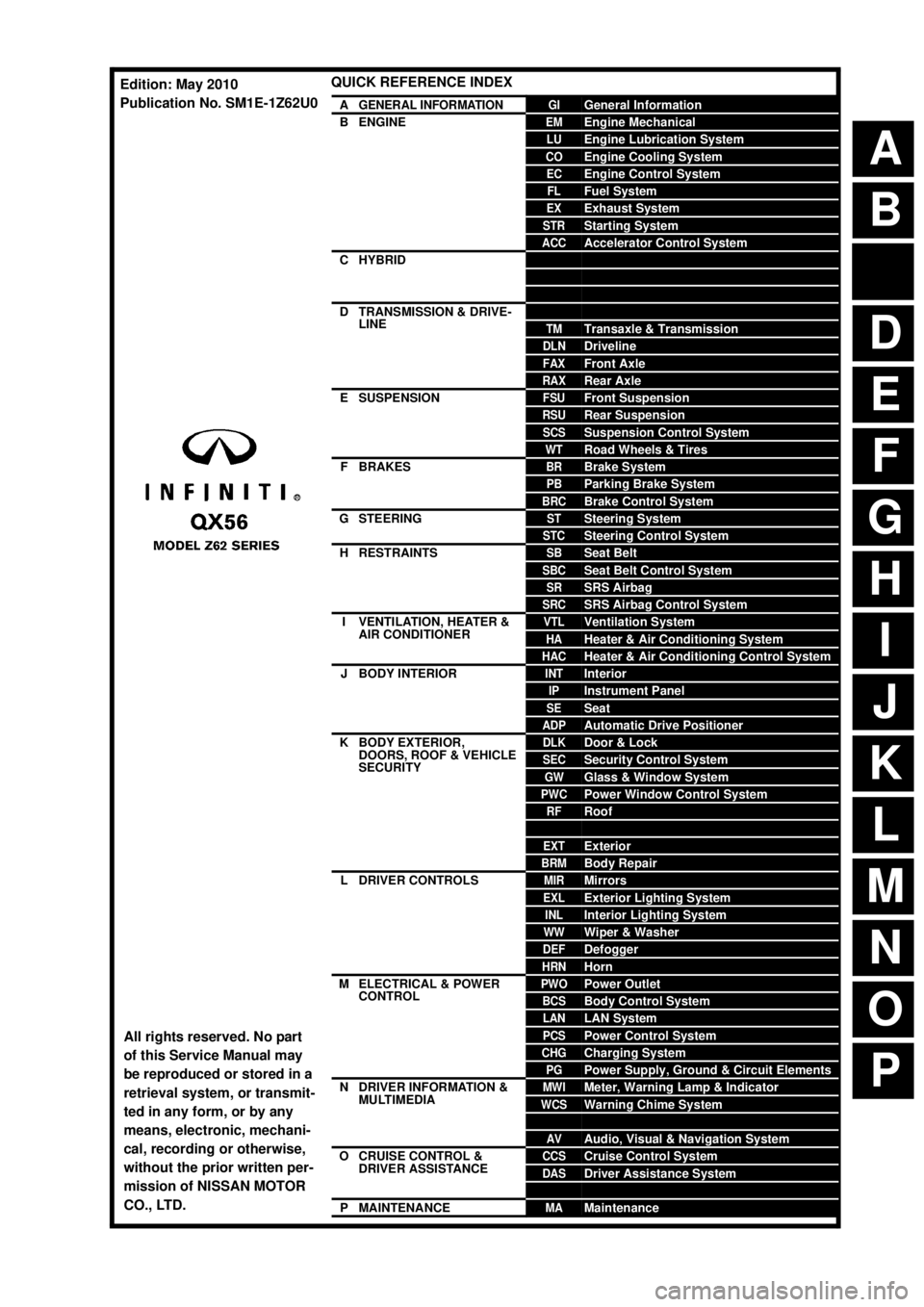
QUICK REFERENCE INDEX
AGENERAL INFORMATIONGIGeneral Information
BENGINEEMEngine Mechanical
LUEngine Lubrication System
COEngine Cooling System
ECEngine Control System
FLFuel System
EXExhaust System
STRStarting System
ACCAccelerator Control System
CHYBRIDHBCHybrid Control System
HBBHybrid Battery System
HBRHybrid Brake System
DTRANSMISSION & DRIVE-
LINECLClutch
TMTransaxle & Transmission
DLNDriveline
FAXFront Axle
RAXRear Axle
ESUSPENSIONFSUFront Suspension
RSURear Suspension
SCSSuspension Control System
WTRoad Wheels & Tires
FBRAKESBRBrake System
PBParking Brake System
BRCBrake Control System
GSTEERINGSTSteering System
STCSteering Control System
HRESTRAINTSSBSeat Belt
SBCSeat Belt Control System
SRSRS Airbag
SRCSRS Airbag Control System
IVENTILATION, HEATER &
AIR CONDITIONERVTLVentilation System
HAHeater & Air Conditioning System
HACHeater & Air Conditioning Control System
JBODY INTERIORINTInterior
IPInstrument Panel
SESeat
ADPAutomatic Drive Positioner
KBODY EXTERIOR,
DOORS, ROOF & VEHICLE
SECURITYDLKDoor & Lock
SECSecurity Control System
GWGlass & Window System
PWCPower Window Control System
RFRoof
HDHood
EXTExterior
BRMBody Repair
LDRIVER CONTROLSMIRMirrors
EXLExterior Lighting System
INLInterior Lighting System
WWWiper & Washer
DEFDefogger
HRNHorn
MELECTRICAL & POWER
CONTROLPWOPower Outlet
BCSBody Control System
LANLAN System
PCSPower Control System
CHGCharging System
PGPower Supply, Ground & Circuit Elements
NDRIVER INFORMATION &
MULTIMEDIAMWIMeter, Warning Lamp & Indicator
WCSWarning Chime System
SNSonar System
AVAudio, Visual & Navigation System
OCRUISE CONTROL &
DRIVER ASSISTANCECCSCruise Control System
DASDriver Assistance System
DMSDrive Mode System
PMAINTENANCEMAMaintenance
All rights reserved. No part
of this Service Manual may
be reproduced or stored in a
retrieval system, or transmit-
ted in any form, or by any
means, electronic, mechani-
cal, recording or otherwise,
without the prior written per-
mission of NISSAN MOTOR
CO., LTD.
Edition: May 2010
Publication No. SM1E-1Z62U0
Page 4 of 5598

QUICK REFERENCE CHART QX56
FRONT WHEEL ALIGNMENT
ELS0003X
*1: The minimum value and maximum value is the same as the nominal value.
Measure value under unladen*2 conditions.
*2: Fuel, engine coolant and lubricant are full. Spare tire, jack, hand tools and mats are in designated positions.
REAR WHEEL ALIGNMENTELS0003Y
Measure value under unladen* conditions.
*: Fuel, engine coolant and lubricant are full. Spare tire, jack, hand tools and mats are in designated positions. Item Standard
Measurement wheel Left side Right side
Camber
Degree minute (Decimal degree) Minimum
−0 °45 ′ ( −0.75 °) −0°55 ′ ( −0.91 °)
Nominal 0 ° 00 ′ (0.00 °) −0°10 ′ ( −0.17 °)
Maximum 0 ° 45 ′ (0.75 °)0 ° 35 ′ (0.58 °)
Left and right difference 0 ° 33 ′ (0.55 °) or less
Caster
Degree minute (Decimal degree) Minimum 2
° 20 ′ (2.34 °)2 ° 40 ′ (2.67 °)
Nominal 3 ° 05 ′ (3.08 °)3 ° 25 ′ (3.42 °)
Maximum 3 ° 50 ′ (3.83 °)4 ° 10 ′
(4.16 °)
Left and right difference 0 ° 45 ′ (0.75 °) or less
Kingpin inclination
Degree minute (Decimal degree) Minimum — —
Nominal
13° 20 ′ (13.33 °)
*113 ° 25 ′ (13.42 °)*1
Maximum — —
Toe-in Total toe-in
Distance
Minimum In 1.4 mm (0.055 in)
Nominal In 2.4 mm (0.094 in)
Maximum In 3.4 mm (0.134 in)
Toe angle (left wheel or right wheel)
Degree minute (Decimal degree) Minimum In 0
° 03 ′ (0.05 °)
Nominal In 0 ° 05 ′ (0.08 °)
Maximum In 0 ° 07 ′ (0.11 °)
Item Standard
Camber
Degree minute (Decimal degree) Minimum –1
° 00 ′ (–1.00 °)
Nominal –0 ° 30 ′ (–0.50 °)
Maximum 0 ° 00 ′ (0.00 °)
Left and right difference 0 ° 45 ′ (0.75 °) or less
To e - i n Total toe-in
Distance
Minimum 0 mm (0 in)
Nominal In 3.4 mm (0.134 in)
Maximum In 6.8 mm (0.268 in)
Toe angle (left wheel or right wheel)
Degree minute (Decimal degree) Minimum 0
° 00 ′ (0.00 °)
Nominal In 0 ° 07 ′ (0.12 °)
Maximum In 0 ° 14 ′ (0.23 °)
2011
Page 160 of 5598

AV-12
< SYSTEM DESCRIPTION >
COMPONENT PARTS
*1: Image signals cannot be received from iPod®.
Side camera RH It inputs the power supply from around view monitor control unit and outputs the
image of the vehicle RH to around view monitor control unit.
It performs the reception/transmission of the communication signal with around view monitor control unit.
Infrared LED
(Auxiliary lighting) It illuminates around the front RH wheel by the power supply from around view
monitor control unit to improve nighttime visibility of front-side view.
The infrared LED is an invisible light ray.
Sonar control unit It is connected with around view monitor control unit via AV communication and
receives the sonar operation signal from around view monitor control unit.
It transmits the sonar detection status to around view monitor control unit via AV
communication.
It judges the warning level according to the signal from corner sensor.
Corner sensor The obstacle distance is detected. The signal is transmitted to sonar control unit.
Steering angle sensor It is connected to the AV control unit and transmits the steering angle sensor signal
via CAN communication.
Microphone Used for hands-free phone operation.
Microphone signal is transmitted to AV control unit.
Power (Microphone VCC) is supplied from AV control unit.
GPS antenna GPS signal is received and transmitted to AV control unit.
Satellite radio antenna Receives the satellite radio waves and outputs it to AV control unit.
Antenna amp. Radio signal received by glass antenna (main) is amplified and transmitted to AV
control unit.
Power (antenna amp. ON signal) is supplied from AV control unit.
USB connector Image signal
*1 and sound signal of USB input is transmitted to AV control unit.
Part name Description
Revision: 2010 May2011 QX56
Page 163 of 5598

AV
SYSTEMAV-15
< SYSTEM DESCRIPTION >
C
DE
F
G H
I
J
K L
M B A
O P
The current position is calculated by detecting the travel distance
from the previous calculation point, and its direction change.
Travel distance The travel distance is generat ed from the vehicle speed sensor
input signal. The automatic distance correction function is adopted
for preventing a miss-detection of the travel distance because of
tire wear etc.
Travel direction The gyroscope (angular veloci ty sensor) and GPS antenna (GPS
information) generate the change of t he travel direction. Both have
advantages and disadvantages as per the following descriptions.
Input signals are prioritized in each situation. However, this order of priority may change in accordance with
more detailed travel conditions so that the tr avel direction is detected more accurately.
Map-matching
Map-matching repositions the vehicle on the road map when a new
location is judged to be more accurate. This is done by comparing
the current vehicle position (calculated by the normal position detec-
tion method) from the map data stored in the HDD (Hard Disk Drive).
There is a possibility that the vehicle position may not be corrected in the following case, and when vehicle is
driven over a certain distance or time in which GPS in formation is hard to receive. Correct manually the cur-
rent location mark on the screen.
In map-matching, several alternative routes are prepared and pri- oritized in addition to the road judged as currently driving on.
Therefore, due to errors in the distance and/or direction, an incor-
rect road may be prioritized, and the current location mark may be
repositioned to the incorrect road.
If two roads are running in parallel, they are of the same priority.
Therefore, the current location mark may appear on either of them
alternately, depending on maneuvering of the steering wheel and
configuration of the road, etc.
SEL684V
Type Advantage Disadvantage
Gyroscope (angular velocity
sensor) The turning angle is precisely detected.
Errors are accumulated when driving a long dis-
tance without stopping.
GPS antenna (GPS informa-
tion) The travel direction (North/South/East/West) is
detected. The travel direction is not precisely detected when
driving slowly.
SEL685V
SEL686V
Revision: 2010 May2011 QX56
Page 170 of 5598

AV-22
< SYSTEM DESCRIPTION >
SYSTEM
Front view guiding lines
REAR VIEW The rear view image is from the rear camera.
When the selector lever is in the reverse position, the rear view is displayed. Backing and parking are
improved by the images from Birds-Eye view and Front-S ide view. The rear wide view function allows the
display of an image with a 180 ° horizontal angle.
Display the vehicle width guiding line and vehicle distance guiding line in Rear view and display the predic- tive course line according to the steering angle (except when using the rear wide view function).
The predictive course line is not di splayed at the steering neutral position.
AV control unit is connected to the steering angle s ensor and receives the steering angle signal via CAN
communication. AV control unit is transmits steering angle signal to around view monitor control unit via AV
communication.
Around view monitor control unit controls the direction and distance of predictive course line according to the
sensor signal from steering angle sensor.
Rear view guiding lines
FRONT-SIDE VIEW
The front-side view image is from the side camera RH.
In Front-Side view, display the vehicle distance guiding line and vehicle width guiding line.
The infrared LED illumination is installed on the door mirror RH to illuminate around the front wheels.
JSNIA0770GB
JSNIA2984GB
Revision: 2010 May2011 QX56
Page 341 of 5598
AV
STEERING SWITCH SIGNAL A CIRCUITAV-193
< DTC/CIRCUIT DIAGNOSIS >
C
DE
F
G H
I
J
K L
M B A
O P
STEERING SWITCH SI GNAL A CIRCUIT
DescriptionINFOID:0000000006216366
Transmits the steering switch signal to AV control unit.
Diagnosis ProcedureINFOID:0000000006216367
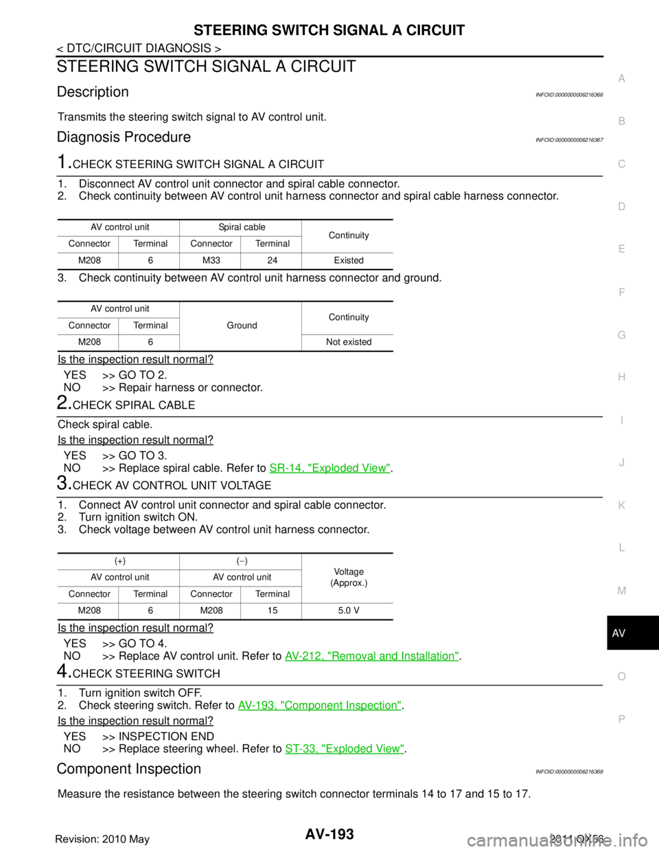
1.CHECK STEERING SWITCH SIGNAL A CIRCUIT
1. Disconnect AV control unit connector and spiral cable connector.
2. Check continuity between AV control unit harness connector and spiral cable harness connector.
3. Check continuity between AV control unit harness connector and ground.
Is the inspection result normal?
YES >> GO TO 2.
NO >> Repair harness or connector.
2.CHECK SPIRAL CABLE
Check spiral cable.
Is the inspection result normal?
YES >> GO TO 3.
NO >> Replace spiral cable. Refer to SR-14, "
Exploded View".
3.CHECK AV CONTROL UNIT VOLTAGE
1. Connect AV control unit connector and spiral cable connector.
2. Turn ignition switch ON.
3. Check voltage between AV control unit harness connector.
Is the inspection result normal?
YES >> GO TO 4.
NO >> Replace AV control unit. Refer to AV-212, "
Removal and Installation".
4.CHECK STEERING SWITCH
1. Turn ignition switch OFF.
2. Check steering switch. Refer to AV-193, "
Component Inspection".
Is the inspection result normal?
YES >> INSPECTION END
NO >> Replace steering wheel. Refer to ST-33, "
Exploded View".
Component InspectionINFOID:0000000006216368
Measure the resistance between the steering s witch connector terminals 14 to 17 and 15 to 17.
AV control unit Spiral cable
Continuity
Connector Terminal Connector Terminal
M208 6 M33 24 Existed
AV control unit GroundContinuity
Connector Terminal
M208 6 Not existed
(+) ( −)
Vo l ta g e
(Approx.)
AV control unit AV control unit
Connector Terminal Connector Terminal M208 6 M208 15 5.0 V
Revision: 2010 May2011 QX56
Page 343 of 5598
AV
STEERING SWITCH SIGNAL B CIRCUITAV-195
< DTC/CIRCUIT DIAGNOSIS >
C
DE
F
G H
I
J
K L
M B A
O P
STEERING SWITCH SI GNAL B CIRCUIT
DescriptionINFOID:0000000006216369
Transmits the steering switch signal to AV control unit.
Diagnosis ProcedureINFOID:0000000006216370
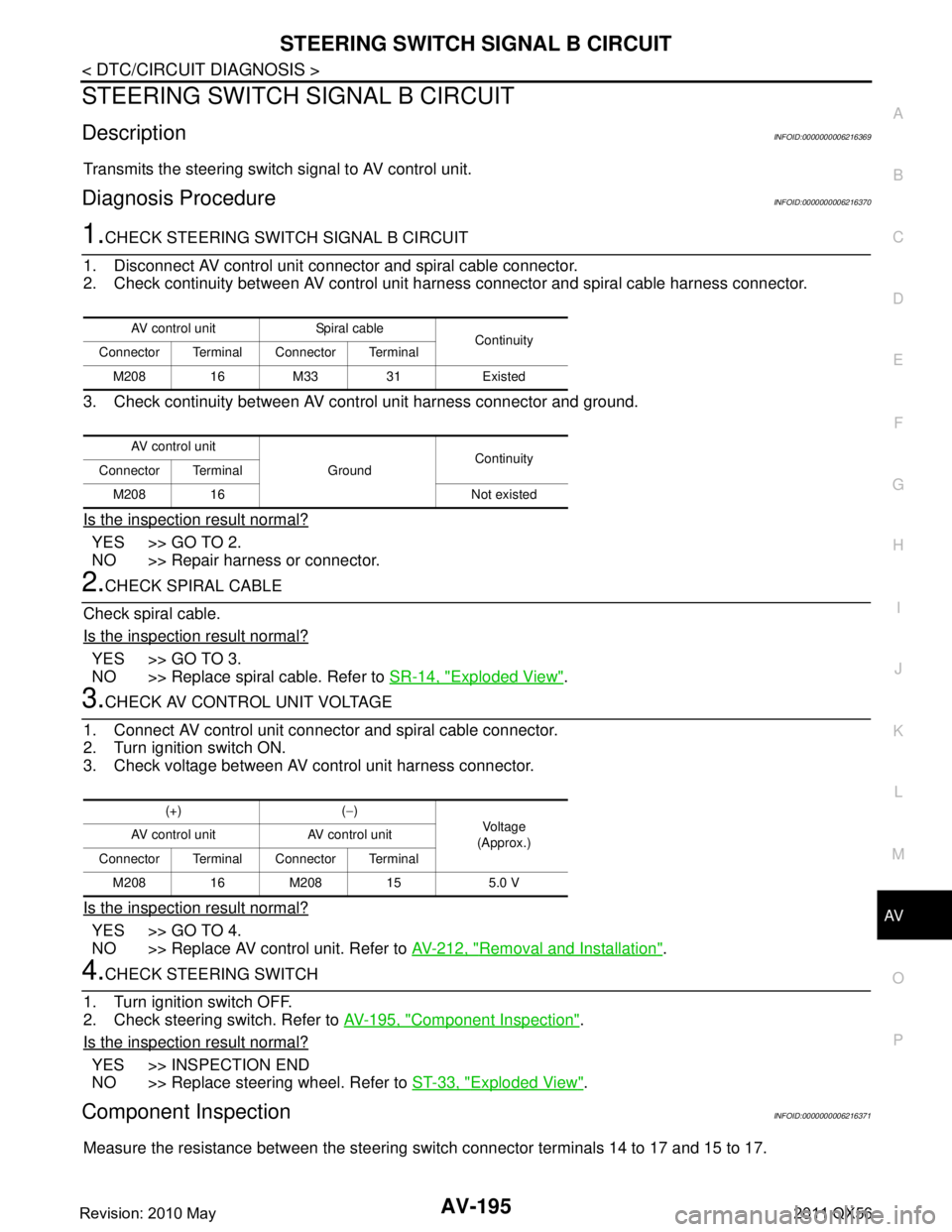
1.CHECK STEERING SWITCH SIGNAL B CIRCUIT
1. Disconnect AV control unit connector and spiral cable connector.
2. Check continuity between AV control unit harness connector and spiral cable harness connector.
3. Check continuity between AV control unit harness connector and ground.
Is the inspection result normal?
YES >> GO TO 2.
NO >> Repair harness or connector.
2.CHECK SPIRAL CABLE
Check spiral cable.
Is the inspection result normal?
YES >> GO TO 3.
NO >> Replace spiral cable. Refer to SR-14, "
Exploded View".
3.CHECK AV CONTROL UNIT VOLTAGE
1. Connect AV control unit connector and spiral cable connector.
2. Turn ignition switch ON.
3. Check voltage between AV control unit harness connector.
Is the inspection result normal?
YES >> GO TO 4.
NO >> Replace AV control unit. Refer to AV-212, "
Removal and Installation".
4.CHECK STEERING SWITCH
1. Turn ignition switch OFF.
2. Check steering switch. Refer to AV-195, "
Component Inspection".
Is the inspection result normal?
YES >> INSPECTION END
NO >> Replace steering wheel. Refer to ST-33, "
Exploded View".
Component InspectionINFOID:0000000006216371
Measure the resistance between the steering s witch connector terminals 14 to 17 and 15 to 17.
AV control unit Spiral cable
Continuity
Connector Terminal Connector Terminal
M208 16 M33 31 Existed
AV control unit GroundContinuity
Connector Terminal
M208 16 Not existed
(+) ( −)
Vo l ta g e
(Approx.)
AV control unit AV control unit
Connector Terminal Connector Terminal M208 16 M208 15 5.0 V
Revision: 2010 May2011 QX56
Page 345 of 5598
AV
STEERING SWITCH GROUND CIRCUITAV-197
< DTC/CIRCUIT DIAGNOSIS >
C
DE
F
G H
I
J
K L
M B A
O P
STEERING SWITCH GROUND CIRCUIT
DescriptionINFOID:0000000006216372
Transmits the steering switch signal to AV control unit.
Diagnosis ProcedureINFOID:0000000006216373
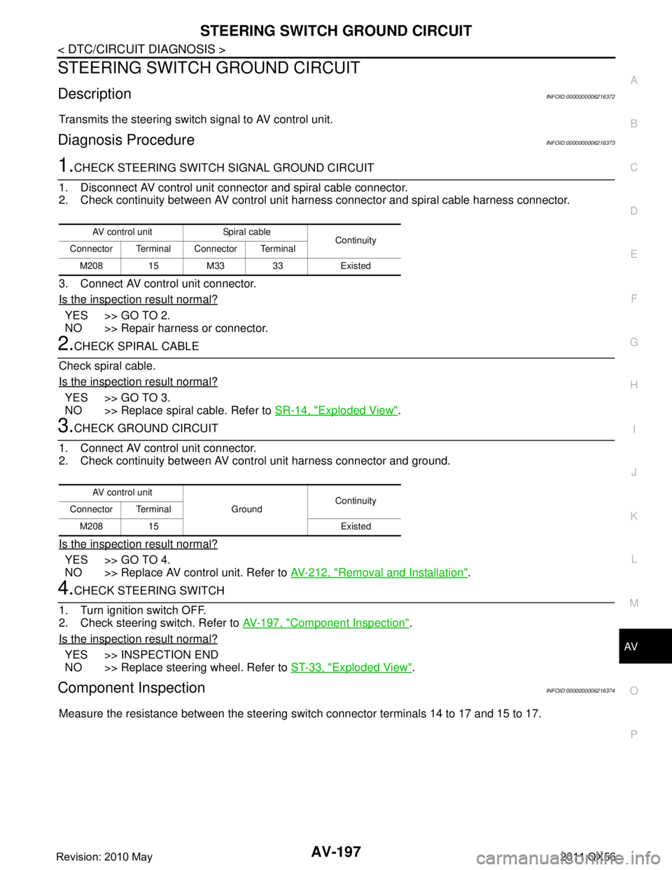
1.CHECK STEERING SWITCH SIGNAL GROUND CIRCUIT
1. Disconnect AV control unit connector and spiral cable connector.
2. Check continuity between AV control unit harness connector and spiral cable harness connector.
3. Connect AV control unit connector.
Is the inspection result normal?
YES >> GO TO 2.
NO >> Repair harness or connector.
2.CHECK SPIRAL CABLE
Check spiral cable.
Is the inspection result normal?
YES >> GO TO 3.
NO >> Replace spiral cable. Refer to SR-14, "
Exploded View".
3.CHECK GROUND CIRCUIT
1. Connect AV control unit connector.
2. Check continuity between AV control unit harness connector and ground.
Is the inspection result normal?
YES >> GO TO 4.
NO >> Replace AV control unit. Refer to AV-212, "
Removal and Installation".
4.CHECK STEERING SWITCH
1. Turn ignition switch OFF.
2. Check steering switch. Refer to AV-197, "
Component Inspection".
Is the inspection result normal?
YES >> INSPECTION END
NO >> Replace steering wheel. Refer to ST-33, "
Exploded View".
Component InspectionINFOID:0000000006216374
Measure the resistance between the steering s witch connector terminals 14 to 17 and 15 to 17.
AV control unit Spiral cable
Continuity
Connector Terminal Connector Terminal
M208 15 M33 33 Existed
AV control unit GroundContinuity
Connector Terminal
M208 15 Existed
Revision: 2010 May2011 QX56
Page 348 of 5598

AV-200
< SYMPTOM DIAGNOSIS >
MULTI AV SYSTEM SYMPTOMS
RELATED TO AROUND VIEW MONITOR
Symptoms Check items Probable malfunction location
Does not recognize cellular
phone connection. (no connec-
tion is displayed on the display
at the guide.) Repeat the registration of cellular phone.
AV control unit malfunction.
Replace AV control unit. Refer to AV- 2 1 2 , "
Removal and
Installation".
Hands-free phone cannot be
established. Hands-free phone operation can be
made, but the communication cannot
be established.
Hands-free phone operation can be performed, however, voice between
each other cannot be heard during the
conversation.
The other party's voice cannot
be heard by hands-free phone. Check the “microphone speaker” in In-
spection & Adjustment Mode if sound is
heard.
Originating sound is not heard
by the other party with hands-
free phone communication. Sound operation function is normal.
Sound operation function does not work.
Microphone signal circuit malfunction.
Refer to
AV- 1 7 8 , "
Diagnosis Procedure".
The system cannot be operat-
ed. The voice recognition can be controlled.
Steering switch's ”VOL UP”, “VOL
DOWN” and “ ” switch works, but
“ ” it does not work. Steering switch malfunction. Replace steering wheel.
Refer to
ST-33, "
Exploded View".
Steering switch's “ ”, ”VOL UP”, “VOL
DOWN” and “ ” switches do not work. Steering switch signal B circuit malfunction.
Refer to
AV- 1 9 5 , "
Diagnosis Procedure".
All steering switches do not work. Steering switch ground circuit malfunction.
Refer to
AV- 1 9 7 , "
Diagnosis Procedure".
Symptoms Check items Probable malfunction location / Action
to take
It does not switch to camera image
even when the “CAMERA” switch is
pressed or the selector lever is in the
reverse position. “Camera Cont.” of “Confirmation/Adjustment” can be
selected.
Ignition signal circuit malfunction
(around view monitor control unit).
“Camera Cont.” of “Confirmation/Adjustment” cannot
be selected. Around view monitor control unit
power supply and ground circuits
malfunction.
Refer to AV- 1 6 4 , "
AROUND VIEW
MONITOR CONTROL UNIT : Diag-
nosis Procedure".
AV communication circuits malfunc- tion.
Refer to AV- 3 9 , "
CONSULT-III Func-
tion".
The screen switches when pressing
the “CAMERA” switch or shifting the
selector lever to the reverse posi-
tion, however, all views are not dis-
played. Only superimposing is displayed.
(Only the image displayed by AV control unit is dis-
played)
Camera image signal circuit between
around view monitor control unit and
front display unit malfunction.
Refer to
AV- 1 8 0 , "
Diagnosis Proce-
dure".
Superimposing is not displayed. Communication circuit between AV control unit and front display unit mal-
function.
Refer to AV- 3 9 , "
CONSULT-III Func-
tion".
Camera image is rolling. —
It cannot be switched to rear view
monitor even when the selector le-
ver is in the reverse position.
The front view is displayed normally.
Reverse signal circuit malfunction. (AV
control unit)
Revision: 2010 May2011 QX56
Page 350 of 5598
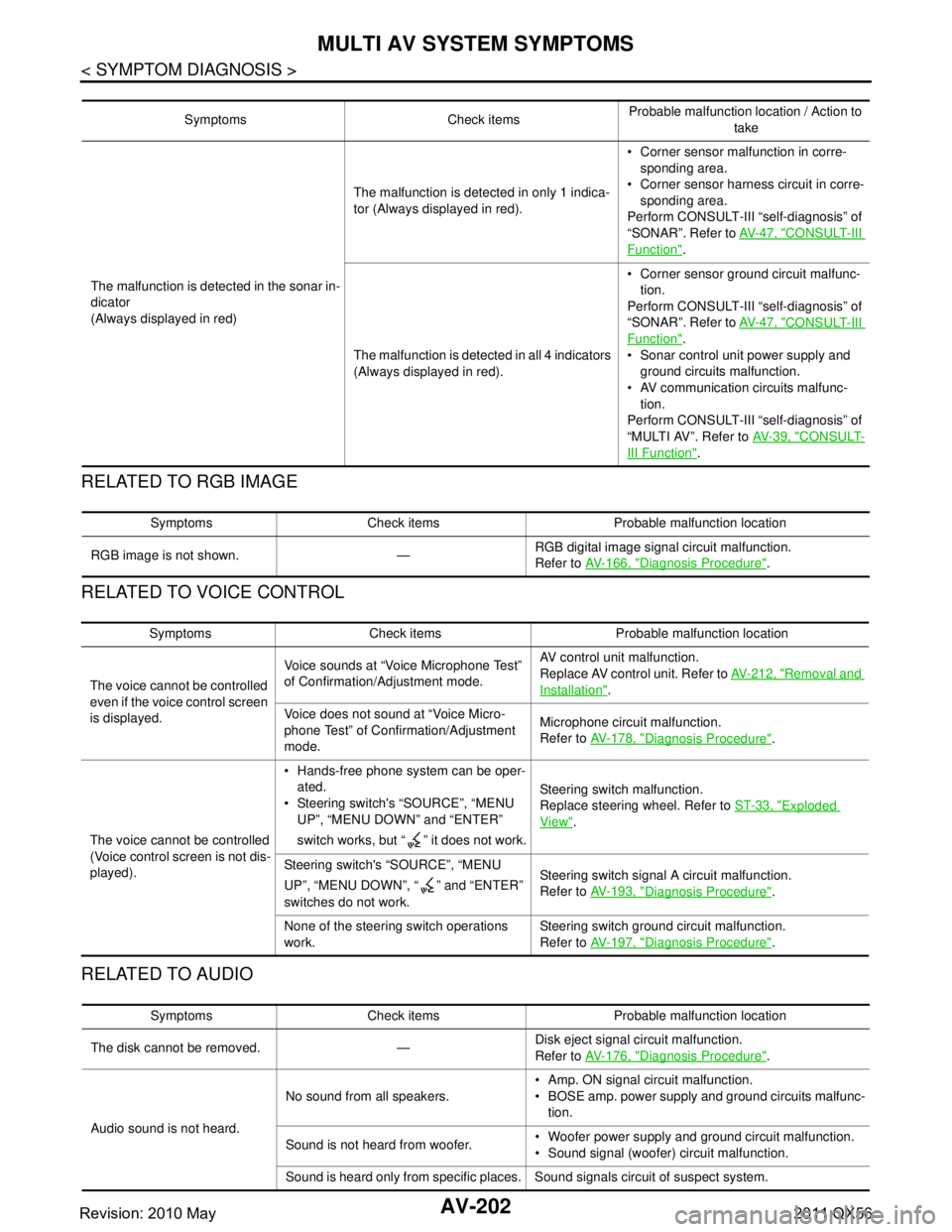
AV-202
< SYMPTOM DIAGNOSIS >
MULTI AV SYSTEM SYMPTOMS
RELATED TO RGB IMAGE
RELATED TO VOICE CONTROL
RELATED TO AUDIO
Symptoms Check itemsProbable malfunction location / Action to
take
The malfunction is detected in the sonar in-
dicator
(Always displayed in red) The malfunction is detected in only 1 indica-
tor (Always displayed in red).
Corner sensor malfunction in corre-
sponding area.
Corner sensor harnes s circuit in corre-
sponding area.
Perform CONSULT-III “self-diagnosis” of
“SONAR”. Refer to AV- 4 7 , "
CONSULT-III
Function".
The malfunction is detected in all 4 indicators
(Always displayed in red). Corner sensor ground circuit malfunc-
tion.
Perform CONSULT-III “self-diagnosis” of
“SONAR”. Refer to AV- 4 7 , "
CONSULT-III
Function".
Sonar control unit power supply and ground circuits malfunction.
AV communication circuits malfunc-
tion.
Perform CONSULT-III “self-diagnosis” of
“MULTI AV”. Refer to AV- 3 9 , "
CONSULT-
III Function".
Symptoms Check items Probable malfunction location
RGB image is not shown. — RGB digital image signal circuit malfunction.
Refer to
AV- 1 6 6 , "
Diagnosis Procedure".
Symptoms Check items Probable malfunction location
The voice cannot be controlled
even if the voice control screen
is displayed. Voice sounds at “Voice Microphone Test”
of Confirmation/Adjustment mode.
AV control unit malfunction.
Replace AV control unit. Refer to
AV- 2 1 2 , "
Removal and
Installation".
Voice does not sound at “Voice Micro-
phone Test” of Confirmation/Adjustment
mode. Microphone circuit malfunction.
Refer to
AV- 1 7 8 , "
Diagnosis Procedure".
The voice cannot be controlled
(Voice control screen is not dis-
played). Hands-free phone system can be oper-
ated.
Steering switch's “SOURCE”, “MENU UP”, “MENU DOWN” and “ENTER”
switch works, but “ ” it does not work. Steering switch malfunction.
Replace steering wheel. Refer to
ST-33, "
Exploded
View".
Steering switch's “SOURCE”, “MENU
UP”, “MENU DOWN”, “ ” and “ENTER”
switches do not work. Steering switch signal A circuit malfunction.
Refer to
AV- 1 9 3 , "
Diagnosis Procedure".
None of the steering switch operations
work. Steering switch ground circuit malfunction.
Refer to
AV- 1 9 7 , "
Diagnosis Procedure".
Symptoms Check items Probable malfunction location
The disk cannot be removed. — Disk eject signal circuit malfunction.
Refer to
AV- 1 7 6 , "
Diagnosis Procedure".
Audio sound is not heard. No sound from all speakers.
Amp. ON signal circuit malfunction.
BOSE amp. power supply and ground circuits malfunc-
tion.
Sound is not heard from woofer. Woofer power supply and ground circuit malfunction.
Sound signal (woofer) circuit malfunction.
Sound is heard only from specific places. Sound signals circuit of suspect system.
Revision: 2010 May2011 QX56