tires INFINITI QX56 2011 Factory Manual PDF
[x] Cancel search | Manufacturer: INFINITI, Model Year: 2011, Model line: QX56, Model: INFINITI QX56 2011Pages: 5598, PDF Size: 94.53 MB
Page 5462 of 5598

WT-12
< SYSTEM DESCRIPTION >
DIAGNOSIS SYSTEM (LOW TIRE PRESSURE WARNING CONTROL UNIT)
DIAGNOSIS SYSTEM (LOW TIRE PRESSURE WARNING CONTROL
UNIT)
CONSULT-III FunctionINFOID:0000000006225496
APPLICATION ITEMS
CONSULT-III performs the following functions in combinat ion of data reception, instruction, and transmission
via communication lines from low tire pressure warning control unit.
*: The following diagnosis information is erased by erasing.
DTC
ECU IDENTIFICATION
Part number of low tire pressure warning control unit is displayed.
SELF DIAGNOSIS RESULTS
Refer to WT-18, "DTC Index".
DATA MONITOR
ACTIVE TEST
NOTE:
After completing the work below, perform an active test.
1. Check ID registration state and perform self-diagnosis.
2. Erase the self-diagnosis result history.
Mode FUNCTION DESCRIPTION
ECU IDENTIFICATION Displays the part number of low tire pressure warning control unit.
SELF-DIAGNOSIS RESULTS Self-diagnosis result can be quickly read.
*
DATA MONITOR Input and output data of low tire pressure warning control unit can be read.
ACTIVE TESTSends command to the low tire pressure warning control unit to change output signals and check
operation of output system.
WORK SUPPORT Components can be quickly and accurately adjusted.
Monitor item (Unit) Remarks
VHCL SPEED SE
[(km/h) or (MPH)] Vehicle speed is displayed.
AIR PRESS FL
[(kPa), (kg/cm
2) or (Psi)] Air pressure of front LH tires is displayed.
AIR PRESS FR
[(kPa), (kg/cm
2) or (Psi)] Air pressure of front RH tires is displayed.
AIR PRESS RR
[(kPa), (kg/cm
2) or (Psi)] Air pressure of rear
RH tires is displayed.
AIR PRESS RL
[(kPa), (kg/cm
2) or (Psi)] Air pressure of rear
LH tires is displayed.
ID REGST FL1 ID registration status of front LH transmitter is displayed.
ID REGST FR1 ID registration status of front RH transmitter is displayed.
ID REGST RR1 ID registration status of rear RH transmitter is displayed.
ID REGST RL1 ID registration status of rear LH transmitter is displayed.
WARNING LAMP Control status of low tire pressure warning lamp is displayed.
BUZZER Control status of buzzer in combination meter by low tire pressure warning con-
trol unit is displayed.
NOTE:
Not use in TPMS, but displayed.
Revision: 2010 May2011 QX56
Page 5475 of 5598

DIAGNOSIS AND REPAIR WORK FLOWWT-25
< BASIC INSPECTION >
C
DF
G H
I
J
K L
M A
B
WT
N
O P
BASIC INSPECTION
DIAGNOSIS AND REPAIR WORK FLOW
Work Flow INFOID:0000000006225501
DETAILED FLOW
1.COLLECT THE INFORMATION FROM THE CUSTOMER
It is also important to clarify customer concerns before starting the inspection. Reproduce the symptom, and
understand it fully. Interview the customer about the concer ns carefully. In some cases, it is necessary to
check the symptoms by driving the vehicle with the customer.
CAUTION:
Customers are not professionals. Never assume“mayb e the customer means...” or “maybe the cus-
tomer mentioned this symptom.
>> GO TO 2.
2.BASIC INSPECTION
1. Turn the ignition switch ON. CAUTION:
Never start the engine.
2. Check the tire pressure for all wheels and adjust to the specified value. Refer to WT-69, "
Tire Air Pres-
sure".
Is the inspection result normal?
YES >> GO TO 3.
NO >> Inspect or repair the tires or wheels.
3.CHECK LOW TIRE PRESSURE WARNING LAMP STATUS
Check low tire pressure warning lamp display.
Does not low tire pressure warning lamp turn OFF?
YES >> GO TO 4.
NO >> GO TO 8.
4.CHECK DTC WITH LOW TIRE PR ESSURE WARNING CONTROL UNIT
With CONSULT-III
Perform the self-diagnosis fo r “AIR PRESSURE MONITOR”.
Is any DTC detected?
YES >> GO TO 5.
NO >> GO TO 8.
5.ERASE DTC MEMORY
With CONSULT-III
1. Record DTC.
2. Erase DTC once.
NOTE:
After erasing DTC record, currently occurr ed DTC can be detected by reading out DTC again.
>> GO TO 6.
6.PERFORM DTC CONFIRMATION PROCEDURE
With CONSULT-III
Perform “DTC CONFIRMATION PROCEDURE” (self-diagnosis) with recorded DTC.
If two or more DTCs are detected, refer to WT-17, "
DTC Inspection Priority Chart" and determine trouble diag-
nosis order.
Is any malfunction detected by self-diagnosis?
YES >> GO TO 7.
Revision: 2010 May2011 QX56
Page 5507 of 5598

LOW TIRE PRESSURE WARNING LAMP DOES NOT TURN OFFWT-57
< SYMPTOM DIAGNOSIS >
C
DF
G H
I
J
K L
M A
B
WT
N
O P
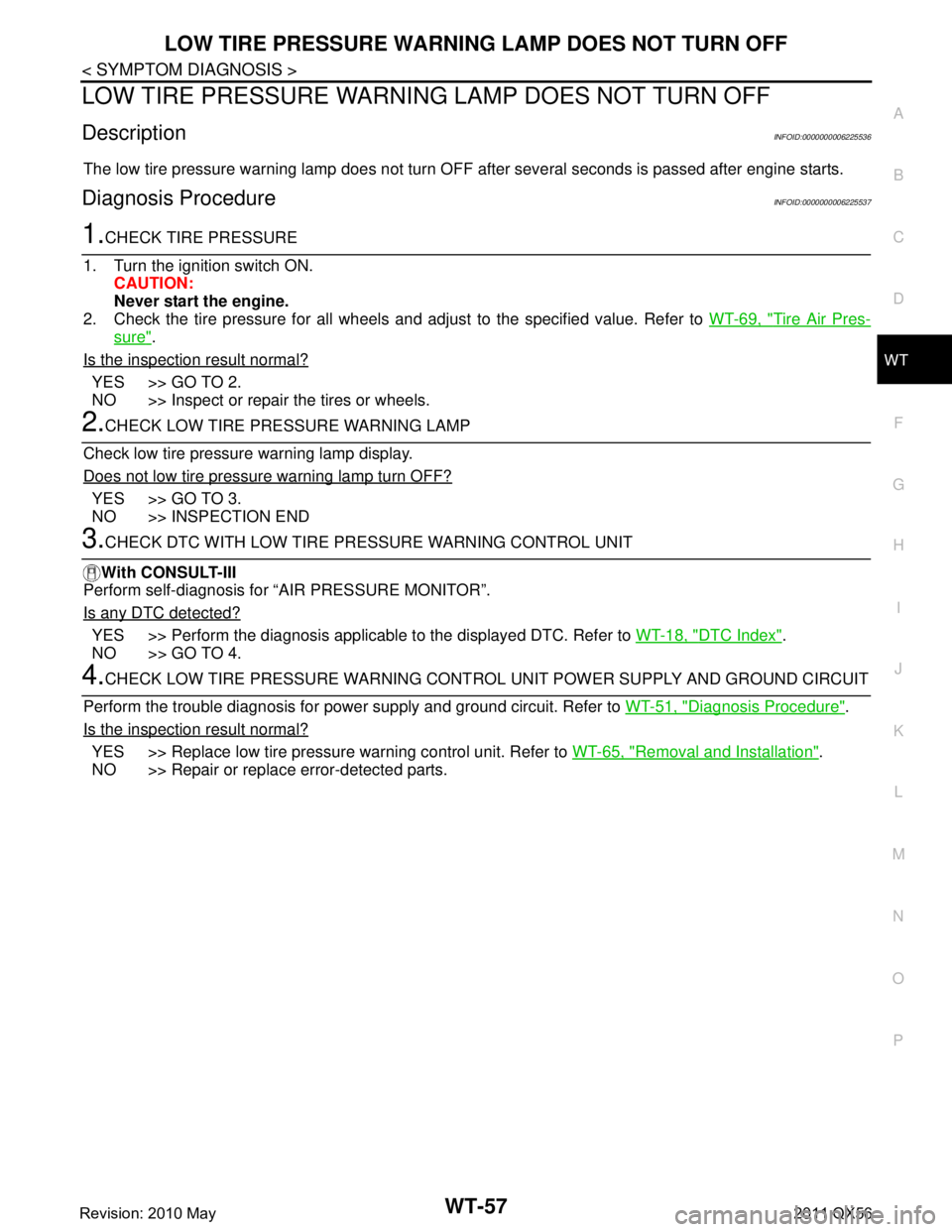
LOW TIRE PRESSURE WARNING LAMP DOES NOT TURN OFF
DescriptionINFOID:0000000006225536
The low tire pressure warning lamp does not turn OFF after several seconds is passed after engine starts.
Diagnosis ProcedureINFOID:0000000006225537
1.CHECK TIRE PRESSURE
1. Turn the ignition switch ON. CAUTION:
Never start the engine.
2. Check the tire pressure for all wheels and adjust to the specified value. Refer to WT-69, "
Tire Air Pres-
sure".
Is the inspection result normal?
YES >> GO TO 2.
NO >> Inspect or repair the tires or wheels.
2.CHECK LOW TIRE PRE SSURE WARNING LAMP
Check low tire pressure warning lamp display.
Does not low tire pressure warning lamp turn OFF?
YES >> GO TO 3.
NO >> INSPECTION END
3.CHECK DTC WITH LOW TIRE PR ESSURE WARNING CONTROL UNIT
With CONSULT-III
Perform self-diagnosis for “AIR PRESSURE MONITOR”.
Is any DTC detected?
YES >> Perform the diagnosis applicable to the displayed DTC. Refer to WT-18, "DTC Index".
NO >> GO TO 4.
4.CHECK LOW TIRE PRESSURE WARNING CONT ROL UNIT POWER SUPPLY AND GROUND CIRCUIT
Perform the trouble diagnosis for power supply and ground circuit. Refer to WT-51, "
Diagnosis Procedure".
Is the inspection result normal?
YES >> Replace low tire pressure warning control unit. Refer to WT-65, "Removal and Installation".
NO >> Repair or replace error-detected parts.
Revision: 2010 May2011 QX56
Page 5509 of 5598

TIRE INFLATION INDICATOR DOES NOT ACTIVATEWT-59
< SYMPTOM DIAGNOSIS >
C
DF
G H
I
J
K L
M A
B
WT
N
O P
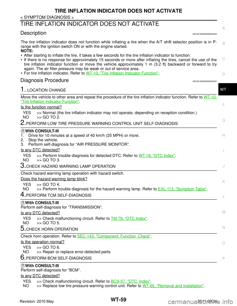
TIRE INFLATION INDICATOR DOES NOT ACTIVATE
DescriptionINFOID:0000000006225540
The tire inflation indicator does not function while inflat ing a tire when the A/T shift selector position is in P-
range with the ignition switch ON or with the engine started.
NOTE:
After starting to inflate the tire, it takes a few seconds for the tire inflation indicator to function.
If there is no response for approximately 15 seconds or mo re after inflating the tires, cancel the use of the
tire inflation indicator function or move the vehicle approximately 1 m (3.2 ft) backward or forward to try
again. The air filler pressure may be weak or out of service area.
For tire inflation indicator, Refer to WT-10, "
Tire Inflation Indicator Function".
Diagnosis ProcedureINFOID:0000000006225541
1. LOCATION CHANGE
Move the vehicle to other area and repeat the procedure of the tire inflation indicator function. Refer to WT-10,
"Tire Inflation Indicator Function".
Is the function normal?
YES >> Normal (the tire inflation indicator may not operate, depending on reception condition.)
NO >> GO TO 2.
2.PERFORM LOW TIRE PRESSURE WARNI NG CONTROL UNIT SELF-DIAGNOSIS
With CONSULT-III
1. Drive for 10 minutes at a speed of 40 km/h (25 MPH) or more.
2. Stop the vehicle.
3. Perform self-diagnosis for “AIR PRESSURE MONITOR”.
Is any DTC detected?
YES >> Perform trouble diagnosis for detected DTC. Refer to WT-18, "DTC Index".
NO >> GO TO 3.
3.CHECK HAZARD WARNING LAMP OPERATION
Check hazard warning lamp operation with hazard switch.
Does the hazard warning lamp blink?
YES >> GO TO 4.
NO >> Perform trouble diagnosis for the hazard warning lamp. Refer to EXL-113, "
Symptom Table".
4.PERFORM TCM SELF-DIAGNOSIS
With CONSULT-III
Perform self-diagnosis for “TRANSMISSION”.
Is any DTC detected?
YES >> Check malfunctioning circuit. Refer to TM-78, "DTC Index".
NO >> GO TO 5.
5.CHECK HORN OPERATION
Check horn operation. Refer to SEC-143, "
ComponentFunctionCheck".
Is the operation normal?
YES >> GO TO 6.
NO >> Repair or replace error-detected parts.
6.PERFORM BCM SELF-DIAGNOSIS
With CONSULT-III
Perform self-diagnosis for “BCM”.
Is any DTC detected?
YES >> Check malfunctioning circuit. Refer to BCS-57, "DTCIndex".
NO >> Replace low tire pressure warning control unit. Refer to WT-65, "
Removal and Installation".
Revision: 2010 May2011 QX56
Page 5511 of 5598

NOISE, VIBRATION AND HARSHNESS (NVH) TROUBLESHOOTINGWT-61
< SYMPTOM DIAGNOSIS >
C
DF
G H
I
J
K L
M A
B
WT
N
O P
NOISE, VIBRATION AND HARSHN ESS (NVH) TROUBLESHOOTING
NVH Troubleshooting ChartINFOID:0000000006225544
Use the chart below to find the cause of the symp tom. If necessary, repair or replace these parts.
×: ApplicableReference
WT-64, "
Exploded View
"
WT-64, "
Inspection
"
WT-62, "
Adjustment
"
WT-69, "
Tire Air Pressure
"
WT-64, "
Inspection
"
—
—
WT-69, "
Tire Air Pressure
"
NVH in DLN section.
NVH in DLN section.
NVH in FAX and FSU sections.
NVH in RAX and RSU sections.
Refer to TIRES in this chart.
Refer to ROAD WHEEL in this chart.
NVH in FAX, RAX section.
NVH in BR section.
NVH in ST section.
Possible cause and SUSPECTED PARTS
Improper installation, looseness
Out-of-round
Unbalance
Incorrect tire pressure
Uneven tire wear
Deformation or damage
Non-uniformity
Incorrect tire size
PROPELLER SHAFT
DIFFERENTIAL
FRONT AXLE AND FRONT SUSPENSION
REAR AXLE AND REAR SUSPENSION
TIRES
ROAD WHEELS
DRIVE SHAFT
BRAKE
STEERING
Symptom TIRESNoise
××××××× ×××× ××××
Shake ×××××× ×× ×× ××××
Vibration ×××××××
Shimmy ×××××××× ×× × ××
Judder ×
××××× × ×× × ××
Poor quality ride or
handling ×××××× × × ××
ROAD
WHEEL Noise
××× × ××××× ×××
Shake ××× × × ××× ×××
Shimmy, Judder ××× × ××× ××
Poor quality ride or
handling ××× × ×××
Revision: 2010 May2011 QX56
Page 5514 of 5598

WT-64
< REMOVAL AND INSTALLATION >
ROAD WHEEL TIRE ASSEMBLY
REMOVAL AND INSTALLATION
ROAD WHEEL TIRE ASSEMBLY
Exploded ViewINFOID:0000000006225547
Removal and InstallationINFOID:0000000006225548
REMOVAL
1. Remove wheel nuts.
2. Remove tire assembly.
INSTALLATION
Note the following, install in the reverse order of removal.
When replacing or rotating wheels, perform the ID registration. Refer to WT-29, "
Work Procedure".
InspectionINFOID:0000000006225549
ALUMINUM WHEEL
1. Check tires for wear and improper inflation.
2. Check wheels for deformation, cracks and other damage. If deformed, remove wheel and check wheel
runout.
a. Remove tire from aluminum wheel and mount on a tire balance machine.
b. Set dial indicator as shown in the figure.
c. Check radial runout, if the latera l deflection (A) or vertical deflec-
tion (B) for radial runout value exceeds the limit, replace alumi-
num wheel.
1. Tire assembly
Refer to GI-4, "
Components" for symbols in the figure.
JPEIC0088GB
Limit
Lateral deflection (A) : Refer to WT-69, "
Road Wheel".
Vertical deflection (B) : Refer to WT-69, "
Road Wheel".
SEIA0737E
Revision: 2010 May2011 QX56