Lock back door INFINITI QX56 2011 Factory Service Manual
[x] Cancel search | Manufacturer: INFINITI, Model Year: 2011, Model line: QX56, Model: INFINITI QX56 2011Pages: 5598, PDF Size: 94.53 MB
Page 16 of 5598
COMPONENT PARTSADP-7
< SYSTEM DESCRIPTION >
C
DE
F
G H
I
K L
M A
B
ADP
N
O P
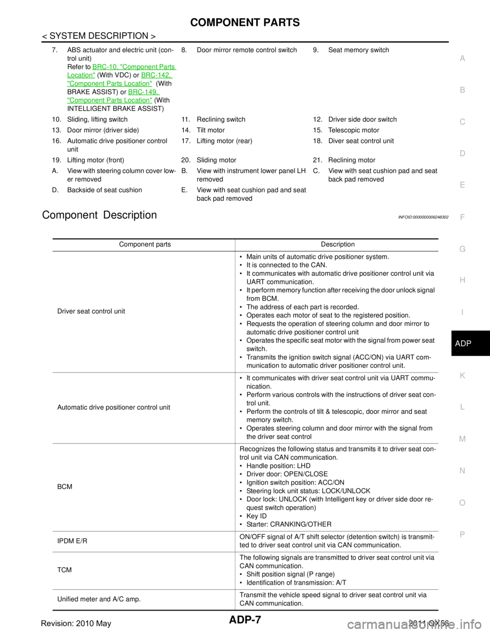
Component DescriptionINFOID:0000000006248302
7. ABS actuator and electric unit (con- trol unit)
Refer to BRC-10, "
Component Parts
Location" (With VDC) or BRC-142,
"Component Parts Location" (With
BRAKE ASSIST) or BRC-149,
"Component Parts Location" (With
INTELLIGENT BRAKE ASSIST) 8. Door mirror remote
control switch 9. Seat memory switch
10. Sliding, lifting switch 11. Reclining switch 12. Driver side door switch
13. Door mirror (driver side) 14. T ilt motor 15. Telescopic motor
16. Automatic drive positioner control unit 17. Lifting motor (rear) 18.
Diver seat control unit
19. Lifting motor (front) 20. Sliding motor 21. Reclining motor
A. View with steering column cover low- er removed B. View with instrument lower panel LH
removed C. View with seat cushion pad and seat
back pad removed
D. Backside of seat cushion E. View with seat cushion pad and seat back pad removed
Component parts Description
Driver seat control unit Main units of automatic drive positioner system.
It is connected to the CAN.
It communicates with automatic drive positioner control unit via
UART communication.
It perform memory function after receiving the door unlock signal
from BCM.
The address of each part is recorded.
Operates each motor of seat to the registered position.
Requests the operation of steering column and door mirror to automatic drive positioner control unit
Operates the specific seat motor with the signal from power seat
switch.
Transmits the ignition switch signal (ACC/ON) via UART com- munication to automatic driver positioner control unit.
Automatic drive positioner control unit It communicates with driver seat control unit via UART commu-
nication.
Perform various controls with the instructions of driver seat con- trol unit.
Perform the controls of tilt & telescopic, door mirror and seat memory switch.
Operates steering column and door mirror with the signal from the driver seat control
BCM Recognizes the following status and transmits it to driver seat con-
trol unit via CAN communication.
Handle position: LHD
Driver door: OPEN/CLOSE
Ignition switch position: ACC/ON
Steering lock unit status: LOCK/UNLOCK
Door lock: UNLOCK (with Intelligent key or driver side door re-
quest switch operation)
Key ID
Starter: CRANKING/OTHER
IPDM E/R ON/OFF signal of A/T shift selector (detention switch) is transmit-
ted to driver seat control unit via CAN communication.
TCM The following signals are transmitted to driver seat control unit via
CAN communication.
Shift position signal (P range)
Identification of transmission: A/T
Unified meter and A/C amp. Transmit the vehicle speed signal to driver seat control unit via
CAN communication.
Revision: 2010 May2011 QX56
Page 21 of 5598

ADP-12
< SYSTEM DESCRIPTION >
SYSTEM
NOTE:
The lumbar support system are controlled independently with no link to the automatic drive positioner system.
Refer to SE-16, "
LUMBAR SUPPORT SYSTEM : System Description".
Sleep control
Driver seat control unit equips sleep control for reducing power consumption.
The system switches to sleep control when al l of the following conditions are satisfied.
Ignition switch is OFF (steering lock status).
All devices of auto driving pos ition system are not operating.
45 seconds timer of driver s eat control unit is not operating.
Set switch and memory switch (1 and 2) are OFF.
Wake-up control
Sleep control releases when detecting status change in either of the following item.
CAN communication
Power seat switch
Set switch and seat memory switch (1 and 2)
Tilt & telescopic switch
MANUAL FUNCTION
Function Description
Manual function The driving position (seat, steering column and door mirror position) can be adjusted
by using the power seat switch, tilt & telescopic switch or door mirror remote control
switch.
Memory function The seat, steering column and door mirror move to the stored driving position by
pressing seat memory switch (1 or 2).
Entry/Exit assist function Exit On exit, the seat moves backward and the steering column moves upward.
Entry
On entry, the seat and steering column returns from exiting position to the previous
driving position.
Intelligent Key interlock function Perform memory operation, exiting operation and entry operation by Intelligent Key
unlock operation or driver side door request switch unlock operation.
Revision: 2010 May2011 QX56
Page 32 of 5598

DIAGNOSIS SYSTEM (DRIVER SEAT CONTROL UNIT)
ADP-23
< SYSTEM DESCRIPTION >
C
D E
F
G H
I
K L
M A
B
ADP
N
O P
TELESCO SW-FR “ON/OFF” ××ON/OFF status judged from the telescoping switch (for-
ward) signal.
TELESCO SW-RR “ON/OFF” ××ON/OFF status judged from the telescoping switch (back-
ward) signal.
MIR CON SW–UP “ON/OFF” ××ON/OFF status judged from the mirror switch (up) signal.
MIR CON SW–DN “ON/OFF” ××ON/OFF status judged from the mirror switch (down) signal.
MIR CON SW–RH “ON/OFF” ××ON/OFF status judged from the door mirror remote control
switch (passenger side) signal.
MIR CON SW–LH “ON/OFF” ××ON/OFF status judged from the door mirror remote control
switch (driver side) signal.
MIR CHNG SW–R “ON/OFF” ××ON/OFF status judged from the door mirror remote control
switch (switching to right) signal.
MIR CHNG SW–L “ON/OFF” ××ON/OFF status judged from the door mirror remote control
switch (switching to left) signal.
VEHICLE SPEED — ××Display the vehicle speed signal received from combination
meter by numerical value [km/h].
P RANG SW CAN “ON/OFF” ××ON/OFF status judged from the P range switch signal.
R RANGE (CAN) “ON/OFF” ××ON/OFF status judged from the R range switch signal.
DOOR SW–FL “ON/OFF” ××ON/OFF status judged from the door switch (front driver
side) signal.
DOOR SW–FR “ON/OFF” ××ON/OFF status judged from the door switch (front passen-
ger side) signal.
IGN ON SW “ON/OFF” ××ON/OFF status judged from the ignition switch signal.
ACC ON SW “ON/OFF” ××ON/OFF status judged from the ACC switch signal.
KEY ON SW “ON/OFF” ××ON/OFF status judged from the key on switch signal.
KEYLESS ID — ××Key ID status judged from the key ID signal.
KYLS DR UNLK “ON/OFF” ××ON/OFF status judged from the driver side door unlock ac-
tuator output switch signal.
VHCL SPEED (ABS) “ON/OFF” ××ON/OFF status judged from vehicle speed signal.
HANDLE “RHD/LHD” ××RHD/LHD status judged from handle position signal.
TRANSMISSION “AT or CVT/
MT” ××
AT or CVT/MT status judged from transmission.
SLIDE PULSE — – ×Value (32768) when battery connections are standard. If it
moves backward, the value increases. If it moves forward,
the value decreases.
RECLN PULSE — – ×Value (32768) when battery connections are standard. If it
moves backward, the value increases. If it moves forward,
the value decreases.
LIFT FR PULSE — – ×Value (32768) when battery connections are standard. If it
moves DOWN, the value increases. If it moves UP, the val-
ue decreases.
LIFT RR PULSE — – ×Value (32768) when battery connections are standard. If it
moves DOWN, the value increases. If it moves UP, the val-
ue decreases.
MIR/SEN RH U–D “V” – ×Voltage input from door mirror sensor (passenger side) up/
down is displayed.
MIR/SEN RH R–L “V” – ×Voltage input from door mirror sensor (passenger side) left/
right is displayed.
MIR/SENLHU–D “V” – ×Voltage input from door mirror
sensor (driver side) up/down
is displayed.
Monitor Item Unit
Main
Signals Selection
From
Menu Contents
Revision: 2010 May2011 QX56
Page 35 of 5598

ADP-26
< ECU DIAGNOSIS INFORMATION >
DRIVER SEAT CONTROL UNIT
TELESCO SW-FR Telescopic switchForward ON
Other than the above OFF
TELESCO SW-RR Telescopic switch Backward ON
Other than the above OFF
DETENT SW A/T shift selector P position OFF
Other than the above ON
STARTER SW Ignition position Cranking ON
Other than the above OFF
SLIDE PULSE Seat sliding Forward The numeral value decreases *
Backward The numeral value increases*
Other than the above No change to numeral value*
RECLN PULSE Seat reclining Forward The numeral value decreases*
Backward
The numeral value increases
*
Other than the above
No change to numeral value*
LIFT FR PULSE Seat lifter (front) Up
The numeral value decreases
*
Down The numeral value increases *
Other than the above
No change to numeral value*
LIFT RR PULSE Seat lifter (rear) Up
The numeral value decreases
*
Down The numeral value increases *
Other than the above No change to numeral value*
MIR/SEN RH U–D Door mirror (passenger side) Change between 3.4 (close to peak)
0.6 (close to valley)
MIR/SEN RH R–L Door mirror (passenger side) Change between 3.4 (close to left edge)
0.6 (close to right edge)
MIR/SEN LH U–D Door mirror (driver side) Change between 3.4 (close to peak)
0.6 (close to valley)
MIR/SEN LH R–L Door mirror (driver side) Change between 0.6 (close to left edge)
3.4 (close to right edge)
TILT PULSE Tilt position Upward
The numeral value decreases
*
Downward The numeral value increases *
Other than the above
No change to numeral value*
TELESCO PULSE Telescopic position Forward
The numeral value decreases
*
Backward The numeral value increases *
Other than the above
No change to numeral value*
STEERING STATUS Steering lock unit LOCK LOCK
unlock UNLOCK
VEHICLE SPEED The condition of vehicle speed is displayed km/h
P RANG SW CAN A/T shift selector P position ON
Other than the above OFF
R RANGE (CAN) A/T shift selector R position ON
Other than the above OFF
DOOR SW-FL Driver door Open ON
Close OFF
Monitor Item Condition Value/Status
Revision: 2010 May2011 QX56
Page 400 of 5598

BCS-12
< SYSTEM DESCRIPTION >
SYSTEM
Low power consumption mode (BCM sleep)- Low power consumption control is active
- CAN transmission is stopped
LOW POWER CONSUMPTION CONTROL WITH BCM
BCM reduces the power consumption with the following operation in the low power consumption mode.
The reading interval of the each switches changes from 10 ms interval to 60 ms interval.
Sleep mode activation
BCM receives the sleep-ready signal (ready) from IPDM E/R, combination meter and automatic back door
control module via CAN communication.
BCM transmits the sleep wake up signal (sleep) to each unit when all of the CAN sleep conditions are ful- filled.
Each unit stops the transmission of CAN communication with the sleep wake up signal. BCM is in CAN com- munication sleep mode.
BCM is in the low power consumption mode and perform the low power consumption control when all of the
BCM sleep conditions are fulfilled with CAN sleep condition.
Sleep condition
Wake-up operation
BCM transmits sleep wake up signal (wake up) to eac h unit when any condition listed below is established,
and then goes into normal mode from low power consumption mode.
Each unit starts transmissions with CAN communication by receiving sleep wake up signals. Each unit trans- mit wake up signals to BCM with CAN communication to convey the start of CAN communication.
CAN sleep condition BCM sleep condition
Receiving the sleep-ready signal (ready) from all units
Ignition switch: OFF
Vehicle security system: Not operation
Warning chime: Not operation
Intelligent Key system buzzer: Not operation
Stop lamp switch: OFF
Turn signal indicator lamp: Not operation
Exterior lamp: OFF
Door lock status: No change
CONSULT-III communication status: Not communication
Meter display signal: Non-transmission
Door switch status: No change
Rear window defogger: OFF
Driver door lock status: No change Interior room lamp battery saver: Time out
RAP system: OFF
IVIS: Not operation
Remote keyless entry receiver communication status: No com-
munication
LOCK indicator lamp: Not operation
ACC indicator lamp: Not operation
ON indicator lamp: Not operation
Revision: 2010 May2011 QX56
Page 401 of 5598

BCS
SYSTEMBCS-13
< SYSTEM DESCRIPTION >
C
DE
F
G H
I
J
K L
B A
O P
N
Wake-up condition
Wake-up condition
Receiving the sleep-ready signal (Not-ready) from any units
Push-button ignition switch (push switch): OFF → ON
Hazard switch: ON
HI BEAM switch: OFF → ON, ON → OFF
PASSING switch: OFF → ON, ON → OFF
HEADLAMP 1 switch: OFF → ON, ON → OFF
HEADLAMP 2 switch: OFF → ON, ON → OFF
TAIL LAMP switch: OFF → ON
FR FOG switch: OFF → ON, ON → OFF
TURN RH: OFF → ON, ON → OFF
TURN LH: OFF → ON, ON → OFF
Driver door switch: OFF → ON, ON → OFF
Passenger door switch: OFF → ON, ON → OFF
Rear RH door switch: OFF → ON, ON → OFF
Rear LH door switch: OFF → ON, ON → OFF
Back door switch: OFF → ON, ON → OFF
Driver door request switch: OFF → ON
Passenger door request switch: OFF → ON
Back door request switch: OFF → ON
Back door opener switch: OFF → ON
Stop lamp switch: ON
Door lock and unlock switch:
NEUTRAL → LOCK, NEUTRAL → UNLOCK
Front door lock assembly (drive r side) (door key cylinder switch):
NEUTRAL → LOCK, NEUTRAL → UNLOCK
Remote keyless entry receiver communication: Receiving
Front door lock assembly (driver side) (unlock sensor):
OFF →
ON, ON → OFF
Revision: 2010 May2011 QX56
Page 402 of 5598

BCS-14
< SYSTEM DESCRIPTION >
DIAGNOSIS SYSTEM (BCM)
DIAGNOSIS SYSTEM (BCM)
COMMON ITEM
COMMON ITEM : CONSULT-III Function (BCM - COMMON ITEM)INFOID:0000000006274796
APPLICATION ITEM
CONSULT-III performs the following functions via CAN communication with BCM.
SYSTEM APPLICATION
BCM can perform the following functions for each system.
NOTE:
It can perform the diagnosis modes except the following for all sub system selection items.
×: Applicable item
*: This item is indicated, but not used.
FREEZE FRAME DATA (FFD)
The BCM records the following vehicle condition at the time a particular DTC is detected, and displays on
CONSULT-III.
Diagnosis mode Function Description
Work Support Changes the setting for each system function.
Self Diagnostic Result Displays the diagnosis results judged by BCM. Refer to BCS-57, "
DTCIndex".
CAN Diag Support Monitor Monitors the reception status of CAN communication viewed from BCM. Refer to CONSULT-III opera-
tion manual.
Data Monitor The BCM input/output signals are displayed.
Active Test The signals used to activate ea ch device are forcibly supplied from BCM.
Ecu Identification The BCM part number is displayed.
Configuration Read and save the vehicle specification.
Write the vehicle specification when replacing BCM.
System Sub system selection item Diagnosis mode
Work Support Data Monitor Active Test
Door lock DOOR LOCK ×××
Rear window defogger REAR DEFOGGER ××
Warning chime BUZZER ××
Interior room lamp timer INT LAMP ×××
Exterior lamp HEAD LAMP ×××
Wiper and washer WIPER ×××
Turn signal and hazard warning lamps FLASHER ×××
— AIR CONDITONER* ××
Intelligent Key system
Engine start system INTELLIGENT KEY
×××
Combination switch COMB SW ×
Body control system BCM ×
IVIS IMMU ×××
Interior room lamp battery saver BATTERY SAVER ×××
Back door TRUNK ×
Vehicle security system THEFT ALM ×××
RAP system RETAINED PWR ×
Signal buffer system SIGNAL BUFFER ××
Revision: 2010 May2011 QX56
Page 404 of 5598

BCS-16
< SYSTEM DESCRIPTION >
DIAGNOSIS SYSTEM (BCM)
DATA MONITOR
ACTIVE TEST
REAR WINDOW DEFOGGER
Monitor item Description
DOOR LOCK-UNLOCK SET Selective unlock function mode can be changed to operation with this mode
On: Operate
Off: Non-operation
AUTOMATIC DOOR LOCK SE-
LECT Automatic door lock function mode can be se
lected from the following in this mode
VH SPD: All doors are locked when vehicle speed more than 24 km/h (15 MPH)
P RANGE: All doors are locked when shifting the selector lever from P position to other than the P position
AUTOMATIC DOOR UNLOCK
SELECT Automatic door unlock function mode can be
selected from the following in this mode
MODE 1: All doors are unlocked when the power supply position is changed from ON to OFF
MODE 2: All doors are unlocked when shifting the selector lever from any position other
than the P to P position
MODE 3: Driver side door is unlocked when the power supply position is changed from ON to OFF
MODE 4: Driver side door is unlocked when shifting the selector lever from any position oth- er than the P to P position
MODE 5: This item is displayed, but cannot be used
MODE 6: This item is displayed, but cannot be used
AUTOMATIC LOCK/UNLOCK
SET Automatic door lock/unlock function mode can be selected from the following in this mode
Off: Non-operation
Unlock Only: Door unlock operation only
Lock Only: Door lock operation only
Lock/Unlock: Lock and unlock operation
Monitor Item Contents
REQ SW-DR Indicated [On/Off] condition of door request switch (driver side)
REQ SW-AS Indicated [On/Off] condition of door request switch (passenger side)
REQ SW-BD/TR Indicated [On/Off] condition of back door request switch
DOOR SW-DR Indicated [On/Off] condition of front door switch (driver side)
DOOR SW-AS Indicated [On/Off] condition of front door switch (passenger side)
DOOR SW-RR Indicated [On/Off] condition of rear door switch RH
DOOR SW-RL Indicated [On/Off] condition of rear door switch LH
DOOR SW-BK Indicated [On/Off] condition of back door switch
CDL LOCK SW Indicated [On/Off] condition of lock signal from door lock unlock switch
CDL UNLOCK SW Indicated [On/Off] condition of unlock signal from door lock unlock switch
KEY CYL LK-SW Indicated [On/Off] condition of lock signal from door key cylinder switch
KEY CYL UN-SW Indicated [On/Off] condition of unlock signal from door key cylinder switch
Te s t i t e m D e s c r i p t i o n
DOOR LOCK This test is able to check door lock/unlock operation
The all door lock actuators are locked when “ALL LOCK” on CONSULT-III screen is touched
The all door lock actuators are unlocked when “ALL UNLK” on CONSULT-III screen is touched
The front door lock actuator (driver side) is unlocked when “DR UNLK” on CONSULT-III screen
is touched
The front door lock actuator (passenger side) is unlocked when “AS UNLK” on CONSULT- III screen is touched
The door lock actuator (other) is unlocked wh en “OTR ULK” on CONSULT-III screen is touched
Revision: 2010 May2011 QX56
Page 407 of 5598

BCS
DIAGNOSIS SYSTEM (BCM)BCS-19
< SYSTEM DESCRIPTION >
C
DE
F
G H
I
J
K L
B A
O P
N
ACTIVE TEST
HEADLAMP
HEADLAMP : CONSULT-III Func
tion (BCM - HEAD LAMP)INFOID:0000000006376461
WORK SUPPORT
PUSH SW
[On/Off] The switch status input from push-button ignition switch
UNLK SEN -DR
[On/Off] Driver door unlock status input from unlock sensor
DOOR SW-DR
[On/Off] The switch status input from door switch (driver side)
DOOR SW-AS
[On/Off] The switch status input from door switch (passenger side)
DOOR SW-RR
[On/Off] The switch status input from rear door switch RH
DOOR SW- RL
[On/Off] The switch status input from rear door switch LH
DOOR SW- BK
[On/Off] The switch status input from back door switch
CDL LOCK SW
[On/Off] Lock switch status input from door lock and unlock switch
CDL UNLOCK SW
[On/Off] Unlock switch status input from door lock and unlock switch
KEY CYL LK-SW
[On/Off] Lock switch status received from door key cylinder switch
KEY CYL UN-SW
[On/Off] Unlock switch status received from door key cylinder switch
TRNK/HAT MNTR
[On/Off] NOTE:
The item is indicated, but not monitored.
RKE-LOCK
[On/Off] Lock signal status received from remote keyless entry receiver
RKE-UNLOCK
[On/Off] Unlock signal status received from remote keyless entry receiver
Monitor item
[Unit] Description
Test item Operation Description
INT LAMP OnOutputs the interior room lamp control signal to turn the interior room lamps ON.
[Map lamp, personal lamp, foot lamp (when applicable lamps switch is in DOOR po-
sition.)]
Off Stops the interior room lamp control signal to turn the interior room lamps OFF.
STEP LAMP TEST On Outputs the step lamp control signal to turn the step lamps ON.
Off Stops the step lamp control signal to turn the step lamps ON.
Service item Setting item Setting
CUSTOM A/LIGHT SETTING MODE 1*
1Normal
MODE 2 More sensitive setting than normal setting (Turns ON earlier than normal opera-
tion)
MODE 3 More sensitive setting than MODE 2 (Turns ON earlier than MODE 2)
MODE 4 Less sensitive setting than normal setting (Turns ON later than normal operation)
Revision: 2010 May2011 QX56
Page 411 of 5598

BCS
DIAGNOSIS SYSTEM (BCM)BCS-23
< SYSTEM DESCRIPTION >
C
DE
F
G H
I
J
K L
B A
O P
N
FLASHER
FLASHER : CONSULT-III F
unction (BCM - FLASHER)INFOID:0000000006376462
WORK SUPPORT
*: Factory setting
DATA MONITOR
ACTIVE TEST
Test item Operation Description
FR WIPER Hi
Transmits the front wiper request signal (HI) to IPDM E/R via CAN communication to op-
erate the front wiper HI operation.
Lo Transmits the front wiper request signal (LO) to IPDM E/R via CAN communication to
operate the front wiper LO operation.
INT Transmits the front wiper request signal (INT) to IPDM E/R via CAN communication to
operate the front wiper INT operation.
Off Stops transmitting the front wiper request signal to stop the front wiper operation.
RR WIPER On Output the voltage to operate the rear wiper motor.
Off Stops the voltage to stop the rear wiper motor.
HEADLAMP WASH-
ER On
Transmits the headlamp washer request signal to IPDM E/R via CAN communication to
operate the headlamp washer operation.
Service item Setting item Setting
HAZARD ANSWER
BACK Lock Only With locking only
Sets the hazard warning lamp answer back function
when the door is lock/unlock with the request switch or
the key fob.
Unlk Only With unlocking only
Lock&Unlk
*With locking/unlocking
Off Without the function
Monitor item [Unit] Description
REQ SW-DR
[On/Off] The switch status input from the request switch (driver side)
REQ SW-AS
[On/Off] The switch status input from the request switch (passenger side)
PUSH SW
[On/Off] The switch status input from the push-button ignition switch
TURN SIGNAL R
[On/Off] Each switch status that BCM detects from the combination switch reading function
TURN SIGNAL L
[On/Off]
HAZARD SW
[On/Off] The switch status input from the hazard switch
RKE-LOCK
[On/Off] Lock signal status received from the remote keyless entry receiver
RKE-UNLOCK
[On/Off] Unlock signal status received from the remote keyless entry receiver
RKE-PANIC
[On/Off] Panic alarm signal status received from the remote keyless entry receiver
Revision: 2010 May2011 QX56