clock INFINITI QX56 2011 Factory Service Manual
[x] Cancel search | Manufacturer: INFINITI, Model Year: 2011, Model line: QX56, Model: INFINITI QX56 2011Pages: 5598, PDF Size: 94.53 MB
Page 177 of 5598
AV
DIAGNOSIS SYSTEM (AV CONTROL UNIT)AV-29
< SYSTEM DESCRIPTION >
C
DE
F
G H
I
J
K L
M B A
O P
METHOD OF STARTING
1. Start the engine.
2. Turn the audio system OFF.
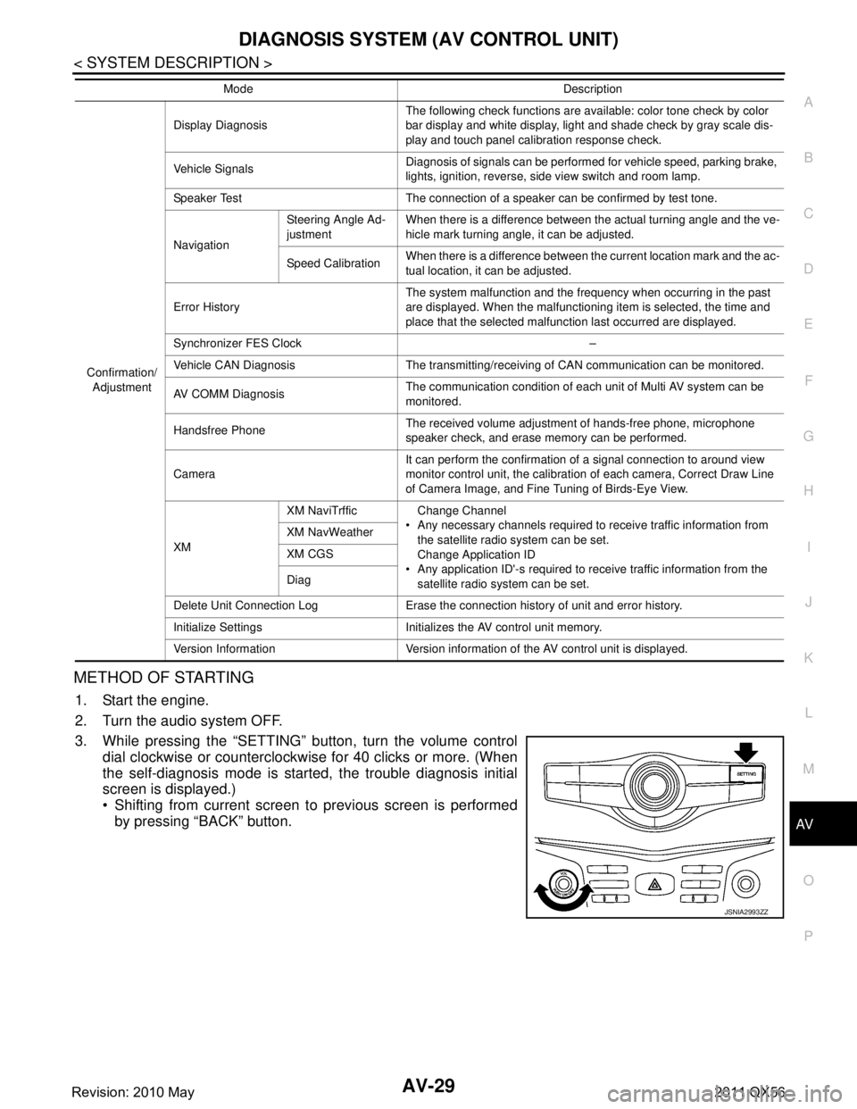
3. While pressing the “SETTING” button, turn the volume control dial clockwise or counterclockwise for 40 clicks or more. (When
the self-diagnosis mode is start ed, the trouble diagnosis initial
screen is displayed.)
Shifting from current screen to previous screen is performed
by pressing “BACK” button.
Confirmation/
Adjustment Display Diagnosis
The following check functions are available: color tone check by color
bar display and white display, light and shade check by gray scale dis-
play and touch panel calibration response check.
Vehicle Signals Diagnosis of signals can be performed for vehicle speed, parking brake,
lights, ignition, reverse, side view switch and room lamp.
Speaker Test The connection of a speaker can be confirmed by test tone.
Navigation Steering Angle Ad-
justment
When there is a difference between the actual turning angle and the ve-
hicle mark turning angle, it can be adjusted.
Speed Calibration When there is a difference between the current location mark and the ac-
tual location, it can be adjusted.
Error History The system malfunction and the frequency when occurring in the past
are displayed. When the malfunctioning item is selected, the time and
place that the selected malfunction last occurred are displayed.
Synchronizer FES Clock –
Vehicle CAN Diagnosis The transmitting/receiving of CAN communication can be monitored.
AV COMM Diagnosis The communication condition of each unit of Multi AV system can be
monitored.
Handsfree Phone The received volume adjustment of hands-free phone, microphone
speaker check, and erase memory can be performed.
Camera It can perform the confirmation of a signal connection to around view
monitor control unit, the calibration
of each camera, Correct Draw Line
of Camera Image, and Fine Tuning of Birds-Eye View.
XM XM NaviTrffic Change Channel
Any necessary channels required to receive traffic information from the satellite radio system can be set.
Change Application ID
Any application ID'-s required to receive traffic information from the satellite radio system can be set.
XM NavWeather
XM CGS
Diag
Delete Unit Connection Log Erase the connection history of unit and error history.
Initialize Settings Initializes the AV control unit memory.
Version Information Version information of the AV control unit is displayed. Mode Description
JSNIA2993ZZ
Revision: 2010 May2011 QX56
Page 478 of 5598
BR-8
< PERIODIC MAINTENANCE >
BRAKE PEDAL
Brake Pedal Height
1. Remove instrument lower panel LH. Refer to IP-14, "Removal and Installation".
2. Disconnect the stop lamp switch harness c onnector and the brake switch harness connector.
3. Loosen the stop lamp switch and brake switch by turning it 45 ° counterclockwise.
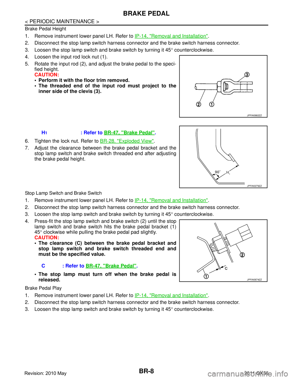
4. Loosen the input rod lock nut (1).
5. Rotate the input rod (2), and adjust the brake pedal to the speci- fied height.
CAUTION:
Perform it with the floor trim removed.
The threaded end of the in put rod must project to the
inner side of the clevis (3).
6. Tighten the lock nut. Refer to BR-28, "
Exploded View".
7. Adjust the clearance between the brake pedal bracket and the stop lamp switch and brake switch threaded end after adjusting
the brake pedal height.
Stop Lamp Switch and Brake Switch
1. Remove instrument lower panel LH. Refer to IP-14, "Removal and Installation".
2. Disconnect the stop lamp switch harness c onnector and the brake switch harness connector.
3. Loosen the stop lamp switch and brake switch by turning it 45 ° counterclockwise.
4. Press-fit the stop lamp switch and brake switch (2) until the stop
lamp switch and brake switch hits the brake pedal bracket (1)
45 ° clockwise while pulling the brake pedal pad slightly.
CAUTION:
The clearance (C) between the brake pedal bracket and
stop lamp switch and brake switch threaded end and
must be the specified value.
The stop lamp must turn off when the brake pedal is released.
Brake Pedal Play
1. Remove instrument lower panel LH. Refer to IP-14, "Removal and Installation".
2. Disconnect the stop lamp switch harness c onnector and the brake switch harness connector.
3. Loosen the stop lamp switch and brake switch by turning it 45 ° counterclockwise.
JPFIA0662ZZ
H1: Refer to BR-47, "Brake Pedal".
JPFIA0279ZZ
C : Refer to BR-47, "Brake Pedal".
JPFIA0674ZZ
Revision: 2010 May2011 QX56
Page 479 of 5598
BRAKE PEDALBR-9
< PERIODIC MAINTENANCE >
C
DE
G H
I
J
K L
M A
B
BR
N
O P
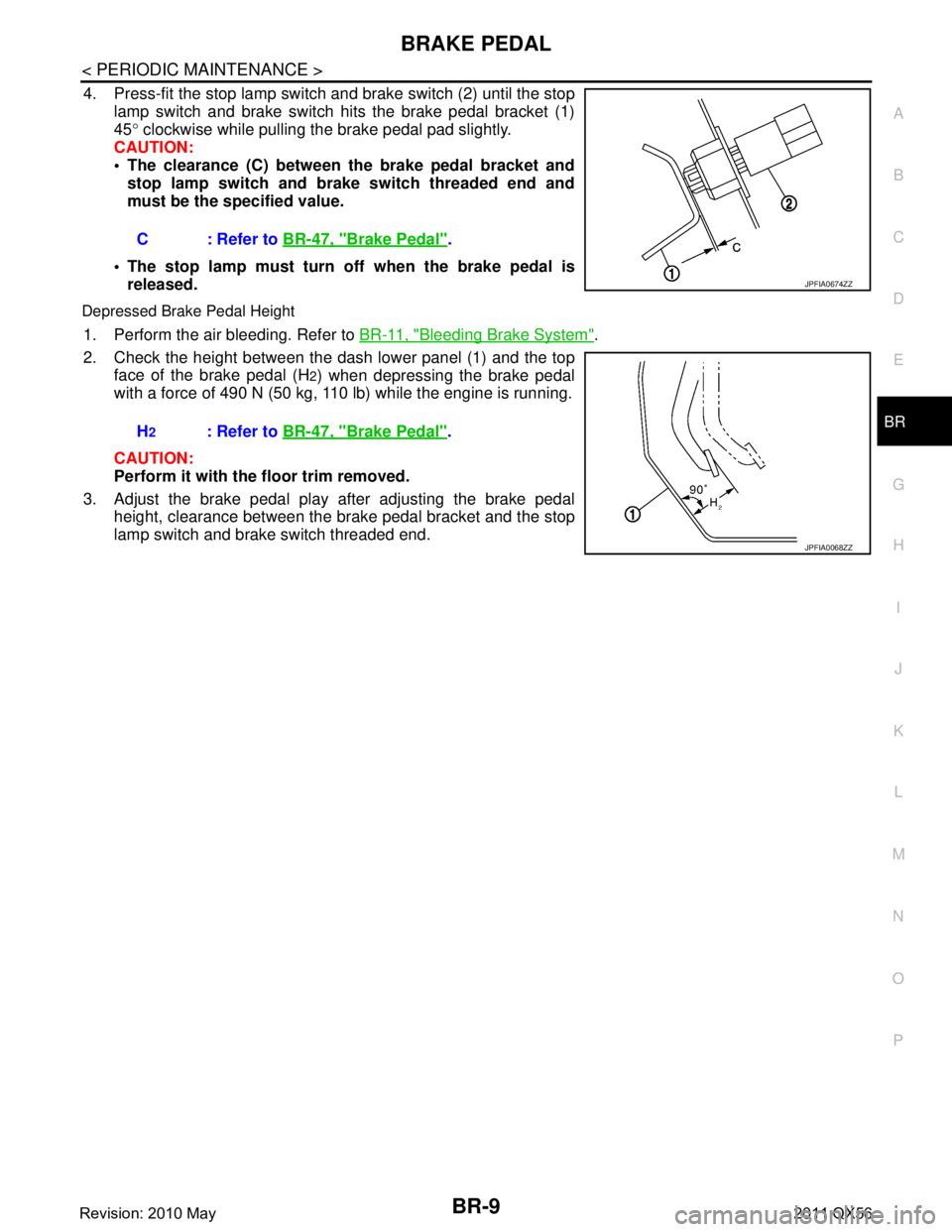
4. Press-fit the stop lamp switch and brake switch (2) until the stop
lamp switch and brake switch hits the brake pedal bracket (1)
45 ° clockwise while pulling the brake pedal pad slightly.
CAUTION:
The clearance (C) between the brake pedal bracket and stop lamp switch and brake switch threaded end and
must be the specified value.
The stop lamp must turn off when the brake pedal is released.
Depressed Brake Pedal Height
1. Perform the air bleeding. Refer to BR-11, "Bleeding Brake System".
2. Check the height between the dash lower panel (1) and the top face of the brake pedal (H
2) when depressing the brake pedal
with a force of 490 N (50 kg, 110 lb) while the engine is running.
CAUTION:
Perform it with the floor trim removed.
3. Adjust the brake pedal play after adjusting the brake pedal height, clearance between the brake pedal bracket and the stop
lamp switch and brake switch threaded end.C : Refer to
BR-47, "
Brake Pedal".
JPFIA0674ZZ
H2: Refer to BR-47, "Brake Pedal".
JPFIA0068ZZ
Revision: 2010 May2011 QX56
Page 490 of 5598
BR-20
< REMOVAL AND INSTALLATION >
BRAKE PEDAL
REMOVAL AND INSTALLATION
BRAKE PEDAL
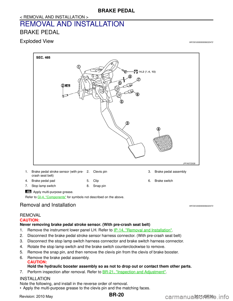
Exploded ViewINFOID:0000000006222472
Removal and InstallationINFOID:0000000006222473
REMOVAL
CAUTION:
Never removing brake pedal stroke sensor. (With pre-crash seat belt)
1. Remove the instrument lower panel LH. Refer to IP-14, "
Removal and Installation".
2. Disconnect the brake pedal stroke sensor har ness connector. (With pre-crash seat belt)
3. Disconnect the stop lamp switch harness connector and brake switch harness connector.
4. Rotate the stop lamp switch and the brake switch counterclockwise to remove.
5. Remove the snap pin, and then remove the clevis pin from the clevis of brake booster.
6. Remove the brake pedal assembly. CAUTION:
Hold the hydraulic booster assembly so as not to drop out or contact them other parts.
7. Perform inspection after removal. Refer to BR-21, "
Inspection and Adjustment".
INSTALLATION
Note the following, and install in the reverse order of removal.
Apply the multi-purpose grease to the clevis pin and the matching faces.
1. Brake pedal stroke sensor (with pre-
crash seat belt) 2. Clevis pin 3. Brake pedal assembly
4. Brake pedal pad 5. Clip 6. Brake switch
7. Stop lamp switch 8. Snap pin : Apply multi-purpose grease.
Refer to GI-4, "
Components" for symbols not described on the above.
JPFIA0723GB
Revision: 2010 May2011 QX56
Page 811 of 5598
![INFINITI QX56 2011 Factory Service Manual
CCS-76
< BASIC INSPECTION >[ICC]
LASER BEAM AIMING ADJUSTMENT
Turn the up-down direction adjusting screw slowly. The value change on display is slower than actual move-
ment of the ICC sensor. Wait INFINITI QX56 2011 Factory Service Manual
CCS-76
< BASIC INSPECTION >[ICC]
LASER BEAM AIMING ADJUSTMENT
Turn the up-down direction adjusting screw slowly. The value change on display is slower than actual move-
ment of the ICC sensor. Wait](/img/42/57033/w960_57033-810.png)
CCS-76
< BASIC INSPECTION >[ICC]
LASER BEAM AIMING ADJUSTMENT
Turn the up-down direction adjusting screw slowly. The value change on display is slower than actual move-
ment of the ICC sensor. Wait for 2 seconds every ti me the up-down direction adjusting screw is turned half a
rotation.
Turning the up-down direction adjusting screw (A) clockwise (C)
directs the laser beam downward. The laser beam directs upward
when turning up-down direction adjusting screw counterclockwise
(B).
CAUTION:
Be careful not to cover the ICC sensor body window with a
hand or the other part of body of worker during adjustment.
>> GO TO 3.
3.LASER BEAM AIMING CONFIRMATION
1. When the “U/D CORRECT” value becomes ±4 or less, check that no value greater than ±4 appears when
the vehicle is left with no load on the ICC s ensor (hand removed) for at least 2 seconds.
2. When “COMPLETED THE VERTICAL AIMING OF LASER BEAM” display appears, touch “END”.
CAUTION:
Always check that the value of “U/D CORRECT” remains ±4 or less when the ICC sensor is left
alone for at least 2 seconds.
3. Check that “ADJUSTING AUTOMATIC HORIZONTAL LASER BEAM AIMING” is displayed and wait for a
short period of time. (The maximum: Approx 10 seconds).
4. Check that “Normally Completed” is displayed, and select “End” to end “LASER BEAM ADJUST”.
CAUTION:
Once “LASER BEAM ADJUST” is started with CONS ULT-III, always continue the work until the
horizontal laser beam aiming ad justment is completed successfully. If the job is stopped midway,
the laser beam aiming is not adjust ed and the ICC system cannot operate.
>> LASER BEAM AIMING ADJUSTMENT END
JSOIA0218ZZ
Revision: 2010 May2011 QX56
Page 1745 of 5598
SQUEAK AND RATTLE TROUBLE DIAGNOSESDLK-209
< SYMPTOM DIAGNOSIS >
C
DE
F
G H
I
J
L
M A
B
DLK
N
O P
SQUEAK AND RATTLE TROUBLE DIAGNOSES
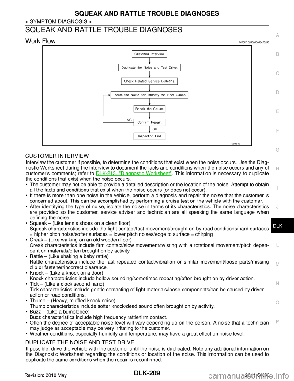
Work FlowINFOID:0000000006425595
CUSTOMER INTERVIEW
Interview the customer if possible, to determine the conditions that exist when the noise occurs. Use the Diag-
nostic Worksheet during the interview to document t he facts and conditions when the noise occurs and any of
customer's comments; refer to DLK-213, "
Diagnostic Worksheet". This information is necessary to duplicate
the conditions that exist when the noise occurs.
The customer may not be able to provide a detailed description or the location of the noise. Attempt to obtain all the facts and conditions that exist when the noise occurs (or does not occur).
If there is more than one noise in the vehicle, perform a diagnosis and repair the noise that the customer is
concerned about. This can be accomplished by performing a cruise test on the vehicle with the customer.
After identifying the type of noise, isolate the noise in terms of its characteristics. The noise characteristics
are provided so the customer, service adviser and technician are all speaking the same language when
defining the noise.
Squeak – (Like tennis shoes on a clean floor)
Squeak characteristics include the light contact/fast movement/brought on by road conditions/hard surfaces
= higher pitch noise/softer surfaces = lower pitch noises/edge to surface = chirping
Creak – (Like walking on an old wooden floor)
Creak characteristics include firm contact/slow mo vement/twisting with a rotational movement/pitch depen-
dent on materials/often brought on by activity.
Rattle – (Like shaking a baby rattle)
Rattle characteristics include the fast repeated contac t/vibration or similar movement/loose parts/missing
clip or fastener/incorrect clearance.
Knock – (Like a knock on a door)
Knock characteristics include hollow sounding/someti mes repeating/often brought on by driver action.
Tick – (Like a clock second hand) Tick characteristics include gentle contacting of li ght materials/loose components/can be caused by driver
action or road conditions.
Thump – (Heavy, muffled knock noise) Thump characteristics include softer k nock/dead sound often brought on by activity.
Buzz – (Like a bumblebee)
Buzz characteristics include high frequency rattle/firm contact.
Often the degree of acceptable noise level will vary depending up on the person. A noise that a technician may judge as acceptable may be very irritating to the customer.
Weather conditions, especially humidity and temperat ure, may have a great effect on noise level.
DUPLICATE THE NOISE AND TEST DRIVE
If possible, drive the vehicle with the customer until the noise is duplicated. Note any additional information on
the Diagnostic Worksheet regarding the conditions or lo cation of the noise. This information can be used to
duplicate the same conditions when the repair is reconfirmed.
SBT842
Revision: 2010 May2011 QX56
Page 1785 of 5598
FUEL FILLER LID OPENERDLK-249
< REMOVAL AND INSTALLATION >
C
DE
F
G H
I
J
L
M A
B
DLK
N
O P
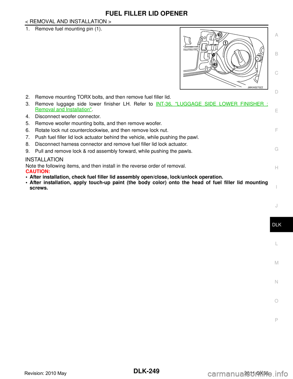
1. Remove fuel mounting pin (1).
2. Remove mounting TORX bolts, and then remove fuel filler lid.
3. Remove luggage side lower finisher LH. Refer to INT-36, "
LUGGAGE SIDE LOWER FINISHER :
Removal and Installation".
4. Disconnect woofer connector.
5. Remove woofer mounting bolts, and then remove woofer.
6. Rotate lock nut counterclockwise, and then remove lock nut.
7. Push fuel filler lid lock actuator behind the vehicle, while pushing the pawl.
8. Disconnect harness connector and remove fuel filler lid lock actuator.
9. Pull and remove lock & rod assembly forward, while pushing the pawls.
INSTALLATION
Note the following items, and then install in the reverse order of removal.
CAUTION:
After installation, check fuel filler li d assembly open/close, lock/unlock operation.
After installation, apply touch-up paint (the body color) onto the head of fuel filler lid mounting
screws.
JMKIA5270ZZ
Revision: 2010 May2011 QX56
Page 1818 of 5598
![INFINITI QX56 2011 Factory Service Manual
DLN-16
< SYSTEM DESCRIPTION >[TRANSFER: ATX90A]
STRUCTURE AND OPERATION
1. Transfer control unit supplies command current to transfer motor.
2. Transfer motor operates and actuator shaft rotates cloc INFINITI QX56 2011 Factory Service Manual
DLN-16
< SYSTEM DESCRIPTION >[TRANSFER: ATX90A]
STRUCTURE AND OPERATION
1. Transfer control unit supplies command current to transfer motor.
2. Transfer motor operates and actuator shaft rotates cloc](/img/42/57033/w960_57033-1817.png)
DLN-16
< SYSTEM DESCRIPTION >[TRANSFER: ATX90A]
STRUCTURE AND OPERATION
1. Transfer control unit supplies command current to transfer motor.
2. Transfer motor operates and actuator shaft rotates clockwise.
3. Shift fork operates according to rotation of actuator shaft. Sun gear and Hi-Lo sleeve are engaged.
4. Ball ramp lever operates in axial direction via cam fixed on actuator shaft according to traction torque of
transfer motor, presses piston, and thrusts multiple plate clutch.
5. Torque is transmitted to front wheels according to thrusting pressure of multiple plate clutch. NOTE:
Torque transmitted to the front wheel is determined according to the command current.
4L MODE
1. Main shaft 2. Ball lamp lever 3. Piston
4. Clutch 5. Hi-Lo sleeve 6. Sun gear
7. Shift fork 8. Actuator shaft 9. Transfer control actuator
JPDIE0278GB
Revision: 2010 May2011 QX56
Page 1819 of 5598
![INFINITI QX56 2011 Factory Service Manual
STRUCTURE AND OPERATIONDLN-17
< SYSTEM DESCRIPTION > [TRANSFER: ATX90A]
C
EF
G H
I
J
K L
M A
B
DLN
N
O P
1. Transfer control unit supplies command current to transfer motor.
2. Transfer motor operate INFINITI QX56 2011 Factory Service Manual
STRUCTURE AND OPERATIONDLN-17
< SYSTEM DESCRIPTION > [TRANSFER: ATX90A]
C
EF
G H
I
J
K L
M A
B
DLN
N
O P
1. Transfer control unit supplies command current to transfer motor.
2. Transfer motor operate](/img/42/57033/w960_57033-1818.png)
STRUCTURE AND OPERATIONDLN-17
< SYSTEM DESCRIPTION > [TRANSFER: ATX90A]
C
EF
G H
I
J
K L
M A
B
DLN
N
O P
1. Transfer control unit supplies command current to transfer motor.
2. Transfer motor operates and actuator shaft rotates counterclockwise.
3. Shift fork operates according to rotation of actuator shaft. Planetary carrier assembly and Hi-Lo sleeve are
engaged.
1. Main shaft 2. Sprocket 3. Lock sleeve
4. Hi-Lo sleeve 5. Sun gear 6. Planetary carrier assembly
7. Internal gear 8. Shift fork 9. Actuator shaft
10. Transfer control actuator
JPDIE0279ZZ
Revision: 2010 May2011 QX56
Page 1873 of 5598
![INFINITI QX56 2011 Factory Service Manual
P1817 TRANSFER MOTORDLN-71
< DTC/CIRCUIT DIAGNOSIS > [TRANSFER: ATX90A]
C
EF
G H
I
J
K L
M A
B
DLN
N
O P
2. Turn the actuator shaft. Refer to DLN-114, "Inspection".
3. Check “ROTARY POSI SEN” of INFINITI QX56 2011 Factory Service Manual
P1817 TRANSFER MOTORDLN-71
< DTC/CIRCUIT DIAGNOSIS > [TRANSFER: ATX90A]
C
EF
G H
I
J
K L
M A
B
DLN
N
O P
2. Turn the actuator shaft. Refer to DLN-114, "Inspection".
3. Check “ROTARY POSI SEN” of](/img/42/57033/w960_57033-1872.png)
P1817 TRANSFER MOTORDLN-71
< DTC/CIRCUIT DIAGNOSIS > [TRANSFER: ATX90A]
C
EF
G H
I
J
K L
M A
B
DLN
N
O P
2. Turn the actuator shaft. Refer to DLN-114, "Inspection".
3. Check “ROTARY POSI SEN” of CONSULT-II I “DATA MONITOR” for “ALL MODE AWD/4WD”.
Is the inspection result normal?
YES >> GO TO 4.
NO >> Transfer assembly is mechanical malfunction. Replace transfer assembly. Refer to DLN-121,
"Removal and Installation".
4.CHECK TERMINALS AND HARNESS CONNECTORS
Check the pin terminals for damage or loose connection with each harness connector.
Is the inspection result normal?
YES >> Replace transfer control unit. Refer to DLN-107, "Removal and Installation".
NO >> Repair or replace error-detected parts.
Component InspectionINFOID:0000000006222270
1.CHECK TRANSFER MOTOR
1. Remove transfer control actuator. Refer to DLN-114, "
Exploded View".
2. Apply 12 V to transfer control actuator connector No. 1 terminal and No. 8 terminal.
CAUTION:
Never make the terminals short.
Connect the fuse between the term inals when applying the voltage.
3. Check the operation of transfer control actuator.
Is the inspection result normal?
YES >> INSPECTION END
NO >> Replace transfer control actuator. Refer to DLN-114, "
Exploded View".
Monitor item Condition Status
ROTARY POSI SEN Turn the actuator shaft. Value is changing
Transfer control actuator Condition Operation
Te r m i n a l
18 Apply the voltage between No. 1 (+)
terminal and No. 8 (
−) terminal. Operate clockwise
Apply the voltage between No. 1 ( −)
terminal and No. 8 (+) terminal. Operate counter-
clockwise
Revision: 2010 May2011 QX56