battery INFINITI QX56 2011 Factory Service Manual
[x] Cancel search | Manufacturer: INFINITI, Model Year: 2011, Model line: QX56, Model: INFINITI QX56 2011Pages: 5598, PDF Size: 94.53 MB
Page 1 of 5598

A
B
D
E
F
G
H
I
J
K
L
M
N
P
O
C
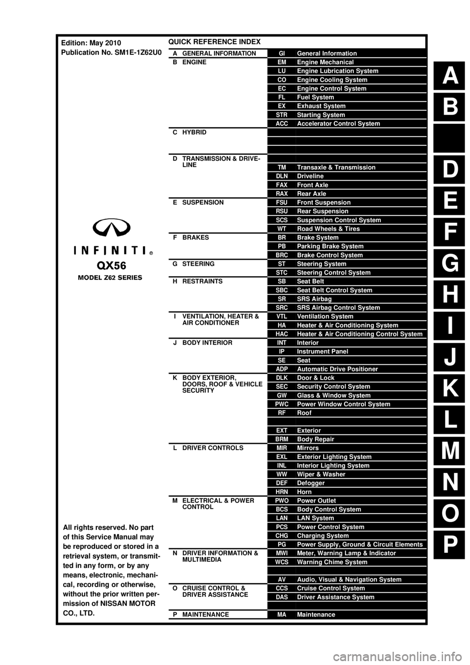
QUICK REFERENCE INDEX
AGENERAL INFORMATIONGIGeneral Information
BENGINEEMEngine Mechanical
LUEngine Lubrication System
COEngine Cooling System
ECEngine Control System
FLFuel System
EXExhaust System
STRStarting System
ACCAccelerator Control System
CHYBRIDHBCHybrid Control System
HBBHybrid Battery System
HBRHybrid Brake System
DTRANSMISSION & DRIVE-
LINECLClutch
TMTransaxle & Transmission
DLNDriveline
FAXFront Axle
RAXRear Axle
ESUSPENSIONFSUFront Suspension
RSURear Suspension
SCSSuspension Control System
WTRoad Wheels & Tires
FBRAKESBRBrake System
PBParking Brake System
BRCBrake Control System
GSTEERINGSTSteering System
STCSteering Control System
HRESTRAINTSSBSeat Belt
SBCSeat Belt Control System
SRSRS Airbag
SRCSRS Airbag Control System
IVENTILATION, HEATER &
AIR CONDITIONERVTLVentilation System
HAHeater & Air Conditioning System
HACHeater & Air Conditioning Control System
JBODY INTERIORINTInterior
IPInstrument Panel
SESeat
ADPAutomatic Drive Positioner
KBODY EXTERIOR,
DOORS, ROOF & VEHICLE
SECURITYDLKDoor & Lock
SECSecurity Control System
GWGlass & Window System
PWCPower Window Control System
RFRoof
HDHood
EXTExterior
BRMBody Repair
LDRIVER CONTROLSMIRMirrors
EXLExterior Lighting System
INLInterior Lighting System
WWWiper & Washer
DEFDefogger
HRNHorn
MELECTRICAL & POWER
CONTROLPWOPower Outlet
BCSBody Control System
LANLAN System
PCSPower Control System
CHGCharging System
PGPower Supply, Ground & Circuit Elements
NDRIVER INFORMATION &
MULTIMEDIAMWIMeter, Warning Lamp & Indicator
WCSWarning Chime System
SNSonar System
AVAudio, Visual & Navigation System
OCRUISE CONTROL &
DRIVER ASSISTANCECCSCruise Control System
DASDriver Assistance System
DMSDrive Mode System
PMAINTENANCEMAMaintenance
All rights reserved. No part
of this Service Manual may
be reproduced or stored in a
retrieval system, or transmit-
ted in any form, or by any
means, electronic, mechani-
cal, recording or otherwise,
without the prior written per-
mission of NISSAN MOTOR
CO., LTD.
Edition: May 2010
Publication No. SM1E-1Z62U0
Page 7 of 5598

ACC-2
< PRECAUTION >
PRECAUTIONS
PRECAUTION
PRECAUTIONS
Precaution for Supplemental Restraint System (SRS) "AIR BAG" and "SEAT BELT
PRE-TENSIONER"
INFOID:0000000006289699
The Supplemental Restraint System such as “A IR BAG” and “SEAT BELT PRE-TENSIONER”, used along
with a front seat belt, helps to reduce the risk or severi ty of injury to the driver and front passenger for certain
types of collision. This system includes seat belt switch inputs and dual stage front air bag modules. The SRS
system uses the seat belt switches to determine the front air bag deployment, and may only deploy one front
air bag, depending on the severity of a collision and w hether the front occupants are belted or unbelted.
Information necessary to service the system safely is included in the “SRS AIR BAG” and “SEAT BELT” of this
Service Manual.
WARNING:
• To avoid rendering the SRS inopera tive, which could increase the risk of personal injury or death in
the event of a collision that would result in air bag inflation, all maintenance must be performed by
an authorized NISS AN/INFINITI dealer.
Improper maintenance, including in correct removal and installation of the SRS, can lead to personal
injury caused by unintent ional activation of the system. For re moval of Spiral Cable and Air Bag
Module, see the “SRS AIR BAG”.
Do not use electrical test equipmen t on any circuit related to the SRS unless instructed to in this
Service Manual. SRS wiring harnesses can be identi fied by yellow and/or orange harnesses or har-
ness connectors.
PRECAUTIONS WHEN USING POWER TOOLS (AIR OR ELECTRIC) AND HAMMERS
WARNING:
When working near the Air Bag Diagnosis Sensor Unit or other Air Bag System sensors with the ignition ON or engine running, DO NOT use air or electric power tools or strike near the sensor(s)
with a hammer. Heavy vibration could activate the sensor(s) and deploy the air bag(s), possibly
causing serious injury.
When using air or electric power tools or hammers , always switch the ignition OFF, disconnect the
battery, and wait at least 3 minu tes before performing any service.
Revision: 2010 May2011 QX56
Page 10 of 5598

ADP-1
BODY INTERIOR
C
DE
F
G H
I
K L
M
SECTION ADP
A
B
ADP
N
O P
CONTENTS
AUTOMATIC DRIVE POSITIONER
PRECAUTION ................ ...............................5
PRECAUTIONS .............................................. .....5
Precaution for Supplemental Restraint System
(SRS) "AIR BAG" and "SEAT BELT PRE-TEN-
SIONER" ............................................................. ......
5
SYSTEM DESCRIPTION ..............................6
COMPONENT PARTS ................................... .....6
Component Parts Location .................................. ......6
Component Description ............................................7
SYSTEM .............................................................11
AUTOMATIC DRIVE POSITIONER SYSTEM ....... ....11
AUTOMATIC DRIVE POSITIONER SYSTEM :
System Diagram ......................................................
11
AUTOMATIC DRIVE POSITIONER SYSTEM :
System Description .................................................
11
MANUAL FUNCTION ............................................ ....12
MANUAL FUNCTION : System Diagram ................13
MANUAL FUNCTION : System Description ............13
MEMORY FUNCTION ........................................... ....14
MEMORY FUNCTION : System Diagram ...............15
MEMORY FUNCTION : System Description ..........15
EXIT ASSIST FUNCTION ...................................... ....17
EXIT ASSIST FUNCTION : System Diagram .........17
EXIT ASSIST FUNCTION : Sy stem Description .....17
ENTRY ASSIST FUNCTION ................................. ....18
ENTRY ASSIST FUNCTION : System Diagram .....18
ENTRY ASSIST FUNCTION : System Description
....
18
INTELLIGENT KEY INTERLOCK FUNCTION ...... ....19
INTELLIGENT KEY INTERLOCK FUNCTION :
System Diagram ......................................................
20
INTELLIGENT KEY INTERLOCK FUNCTION :
System Description .................................................
20
Fail Safe .............................................................. ....21
DIAGNOSIS SYSTEM (DRIVER SEAT CON-
TROL UNIT) ......................................................
22
CONSULT-III Function ............................................22
ECU DIAGNOSIS INFORMATION ..............25
DRIVER SEAT CONTROL UNIT ......................25
Reference Value .................................................. ....25
Fail Safe ..................................................................30
DTC Index ...............................................................31
AUTOMATIC DRIVE POSITIONER CON-
TROL UNIT ........................................................
32
Reference Value ......................................................32
BCM (BODY CONTROL MODULE) .................35
List of ECU Reference .............................................35
WIRING DIAGRAM ......................................36
AUTOMATIC DRIVE POSITIONER SYSTEM ...36
Wiring Diagram .................................................... ....36
BASIC INSPECTION ...................................48
DIAGNOSIS AND REPAIR WORK FLOW .......48
Work Flow ............................................................ ....48
INSPECTION AND ADJUSTMENT ..................51
ADDITIONAL SERVICE WHEN REMOVING BAT-
TERY NEGATIVE TERMINAL ............................... ....
51
ADDITIONAL SERVICE WHEN REMOVING
BATTERY NEGATIVE TERMINAL : Description .....
51
ADDITIONAL SERVICE WHEN REMOVING
BATTERY NEGATIVE TERMINAL : Special Re-
pair Requirement .....................................................
51
ADDITIONAL SERVICE WHEN REPLACING
CONTROL UNIT .................................................... ....
51
Revision: 2010 May2011 QX56
Page 14 of 5598

PRECAUTIONSADP-5
< PRECAUTION >
C
DE
F
G H
I
K L
M A
B
ADP
N
O P
PRECAUTION
PRECAUTIONS
Precaution for Supplemental Restraint System (SRS) "AIR BAG" and "SEAT BELT
PRE-TENSIONER"
INFOID:0000000006248300
The Supplemental Restraint System such as “A IR BAG” and “SEAT BELT PRE-TENSIONER”, used along
with a front seat belt, helps to reduce the risk or severi ty of injury to the driver and front passenger for certain
types of collision. This system includes seat belt switch inputs and dual stage front air bag modules. The SRS
system uses the seat belt switches to determine the front air bag deployment, and may only deploy one front
air bag, depending on the severity of a collision and whether the front occupants are belted or unbelted.
Information necessary to service the system safely is included in the “SRS AIR BAG” and “SEAT BELT” of this
Service Manual.
WARNING:
• To avoid rendering the SRS inoper ative, which could increase the risk of personal injury or death in
the event of a collision that would result in air ba g inflation, all maintenance must be performed by
an authorized NISSAN/INFINITI dealer.
Improper maintenance, including in correct removal and installation of the SRS, can lead to personal
injury caused by unintentional act ivation of the system. For removal of Spiral Cable and Air Bag
Module, see the “SRS AIR BAG”.
Do not use electrical test equipm ent on any circuit related to the SRS unless instructed to in this
Service Manual. SRS wiring harnesses can be identi fied by yellow and/or orange harnesses or har-
ness connectors.
PRECAUTIONS WHEN USING POWER TOOLS (AIR OR ELECTRIC) AND HAMMERS
WARNING:
When working near the Air Bag Diagnosis Sensor Unit or other Air Bag System sensors with the
ignition ON or engine running, DO NOT use air or electric power tools or strike near the sensor(s)
with a hammer. Heavy vibration could activate the sensor(s) and deploy the air bag(s), possibly
causing serious injury.
When using air or electric power tools or hammers , always switch the ignition OFF, disconnect the
battery, and wait at least 3 minutes before performing any service.
Revision: 2010 May2011 QX56
Page 32 of 5598

DIAGNOSIS SYSTEM (DRIVER SEAT CONTROL UNIT)
ADP-23
< SYSTEM DESCRIPTION >
C
D E
F
G H
I
K L
M A
B
ADP
N
O P
TELESCO SW-FR “ON/OFF” ××ON/OFF status judged from the telescoping switch (for-
ward) signal.
TELESCO SW-RR “ON/OFF” ××ON/OFF status judged from the telescoping switch (back-
ward) signal.
MIR CON SW–UP “ON/OFF” ××ON/OFF status judged from the mirror switch (up) signal.
MIR CON SW–DN “ON/OFF” ××ON/OFF status judged from the mirror switch (down) signal.
MIR CON SW–RH “ON/OFF” ××ON/OFF status judged from the door mirror remote control
switch (passenger side) signal.
MIR CON SW–LH “ON/OFF” ××ON/OFF status judged from the door mirror remote control
switch (driver side) signal.
MIR CHNG SW–R “ON/OFF” ××ON/OFF status judged from the door mirror remote control
switch (switching to right) signal.
MIR CHNG SW–L “ON/OFF” ××ON/OFF status judged from the door mirror remote control
switch (switching to left) signal.
VEHICLE SPEED — ××Display the vehicle speed signal received from combination
meter by numerical value [km/h].
P RANG SW CAN “ON/OFF” ××ON/OFF status judged from the P range switch signal.
R RANGE (CAN) “ON/OFF” ××ON/OFF status judged from the R range switch signal.
DOOR SW–FL “ON/OFF” ××ON/OFF status judged from the door switch (front driver
side) signal.
DOOR SW–FR “ON/OFF” ××ON/OFF status judged from the door switch (front passen-
ger side) signal.
IGN ON SW “ON/OFF” ××ON/OFF status judged from the ignition switch signal.
ACC ON SW “ON/OFF” ××ON/OFF status judged from the ACC switch signal.
KEY ON SW “ON/OFF” ××ON/OFF status judged from the key on switch signal.
KEYLESS ID — ××Key ID status judged from the key ID signal.
KYLS DR UNLK “ON/OFF” ××ON/OFF status judged from the driver side door unlock ac-
tuator output switch signal.
VHCL SPEED (ABS) “ON/OFF” ××ON/OFF status judged from vehicle speed signal.
HANDLE “RHD/LHD” ××RHD/LHD status judged from handle position signal.
TRANSMISSION “AT or CVT/
MT” ××
AT or CVT/MT status judged from transmission.
SLIDE PULSE — – ×Value (32768) when battery connections are standard. If it
moves backward, the value increases. If it moves forward,
the value decreases.
RECLN PULSE — – ×Value (32768) when battery connections are standard. If it
moves backward, the value increases. If it moves forward,
the value decreases.
LIFT FR PULSE — – ×Value (32768) when battery connections are standard. If it
moves DOWN, the value increases. If it moves UP, the val-
ue decreases.
LIFT RR PULSE — – ×Value (32768) when battery connections are standard. If it
moves DOWN, the value increases. If it moves UP, the val-
ue decreases.
MIR/SEN RH U–D “V” – ×Voltage input from door mirror sensor (passenger side) up/
down is displayed.
MIR/SEN RH R–L “V” – ×Voltage input from door mirror sensor (passenger side) left/
right is displayed.
MIR/SENLHU–D “V” – ×Voltage input from door mirror
sensor (driver side) up/down
is displayed.
Monitor Item Unit
Main
Signals Selection
From
Menu Contents
Revision: 2010 May2011 QX56
Page 33 of 5598

ADP-24
< SYSTEM DESCRIPTION >
DIAGNOSIS SYSTEM (DRIVER SEAT CONTROL UNIT)
ACTIVE TEST
CAUTION:
When driving vehicle, do not perform active test.
WORK SUPPORT
MIR/SEN LH R–L “V” –×Voltage input from door mirror sensor (driver side) left/right
is displayed.
TILT PULSE — – ×Value (32768) when battery connections are standard. If it
moves DOWN, the value increases. If it moves UP, the val-
ue decreases.
TELESCO PULSE — – ×Value (32768) when battery connections are standard. If it
moves backward, the value increases. If it moves forward,
the value decreases.
Monitor Item Unit
Main
Signals Selection
From
Menu Contents
Test item Description
SEAT SLIDE Activates/deactivates the sliding motor.
SEAT RECLINING Activates/deactivates the reclining motor.
SEAT LIFTER FR Activates/deactivates the lifting motor (front).
SEAT LIFTER RR Activates/deactivates the lifting motor (rear).
TILT MOTOR Activates/deactivates the tilt motor.
TELESCO MOTOR Activates/deactivates the telescopic motor.
MIRROR MOTOR RH Activates/deactivates the mirror motor (passenger side).
MIRROR MOTOR LH Activates/deactivates the mirror motor (driver side).
MEMORY SW INDCTR Turns ON/O FF the memory indicator.
Work item Content Item
SEAT SLIDE VOLUME SET The amount of seat sliding for entry/exit assist can be selected
from 3 items. 40 mm
80 mm
150 mm
EXIT TILT SETTING Entry/exit assist (steering column) can be selected:
ON (operated) – OFF (not operated) ON
OFF
EXIT SEAT SLIDE SETTING Entry/exit assist (seat) can be selected:
ON (operated) – OFF (not operated) ON
OFF
Revision: 2010 May2011 QX56
Page 36 of 5598

DRIVER SEAT CONTROL UNITADP-27
< ECU DIAGNOSIS INFORMATION >
C
DE
F
G H
I
K L
M A
B
ADP
N
O P
*: The value at the position attained when the battery is connected is regarded as 32768.
TERMINAL LAYOUT
PHYSICAL VALUES
DOOR SW-FR Passenger door Open ON
Close OFF
IGN ON SW Ignition switch ON position ON
Other than the above OFF
ACC ON SW Ignition switch ACC or ON position ON
Other than the above OFF
KEY ON SW Intelligent Key Inserted is key slot ON
Inserted is not key slot OFF
KEYLESS ID UNLOCK button of Intelligent Key is pressed 1, 2, 3, 4 or 5
KYLS DR UNLK Intelligent Key or driver
side door request switch ON ON
OFF OFF
VHCL SPEED (ABS) Can signal from ABS Received ON
Not received OFF
HANDLE The BCM for handle position is displayed LHD
RHD
TRANSMISSION Transmission type is displayed AT o r C V T
MT
Monitor Item Condition Value/Status
JMJIA3903ZZ
Te r m i n a l N o .
(Wire color) Description
ConditionVoltage (V)
(Approx.)
+ - Signal name Input/
output
1
(R/Y) —CAN-H — — —
2
(R) Ground UART communication
(TX/RX) Input Ignition switch ON
JMJIA1391ZZ
Revision: 2010 May2011 QX56
Page 39 of 5598

ADP-30
< ECU DIAGNOSIS INFORMATION >
DRIVER SEAT CONTROL UNIT
Fail Safe
INFOID:0000000006248318
The fail-safe mode may be activated if the following symptoms are observed.
33
(R) Ground Battery power supply Input — Battery voltage
34
(B) Ground Sliding motor back-
ward output signal Output Seat sliding Operate
(backward)
12
Other than the
above 0
35
(G) Ground
Reclining motor for-
ward output signal Output Seat reclining Operate
(forward)
12
Other than the
above 0
36
(L) Ground Lifting motor (front)
down output signal
Output Seat lifting (front) Operate
(down)
12
Other than the
above 0
38
(GR) Ground Sliding motor forward
output signal Output Seat sliding Operate
(forward)
12
Other than the
above 0
39
(Y) Ground
Reclining motor back-
ward output signal Output Seat reclining Operate
(backward)
12
Other than the
above 0
40
(W) Ground Lifting motor (front) up
output signal
Output Seat lifting (front) Operate
(up)
12
Other than the
above 0
41
(V) Ground Lifting motor (rear) up
output signal Output Seat lifting (rear) Operate
(up)
12
Other than the
above 0
42
(P/B) Ground
Lifting motor (rear)
down output signal Output Seat lifting (rear) Operate
(down)
12
Other than the
above 0
43
(LG) Ground Ground — — 0
Operating in
fail-safe mode Malfunction ItemRelated
DTC Diagnosis
Only manual functions operate normally. CAN communication U1000
ADP-56
CONTROL UNIT U1010ADP-57
EEPROM B2130ADP-66
Only manual functions, except door mirror, operate normally. UART communication B2128 ADP-64
Only manual functions, except seat sliding, operate normally. Seat sliding output B2112ADP-58
Only manual functions, except seat reclining, operate normally. Seat reclining output B2113ADP-60
Only manual functions, except steering tilt, operate normally. Steering column tilt output B2116ADP-62
Revision: 2010 May2011 QX56
Page 43 of 5598

ADP-34
< ECU DIAGNOSIS INFORMATION >
AUTOMATIC DRIVE POSITIONER CONTROL UNIT
24
(BR/Y) Ground Door mirror motor (driver
side) left output signal
Output Door mirror (LH) Operate
(left)
12
Other than the
above 0
25
(W/R) Ground Battery power supply Input — Battery voltage
26
(L) Ground Telescopic motor back-
ward output signal
OutputSteering tele-
scopic Operate
(backward)
12
Other than the
above 0
27
(P) Ground Tilt & telescopic sensor
power supply
Output — 12
28
(G) Ground Tilt motor down output
signal
Output Steering tilt Operate
(down)
12
Other than the
above 0
29
(W/B) Ground Tilt motor up output sig-
nal
OutputSteering tilt
Operate
(up)
12
Other than the
above 0
Telescopic motor for-
ward output signal Steering tele-
scopicOperate
(forward)
12
Other than the
above 0
30
(B) Ground Ground — — 0
Te r m i n a l N o .
(wire color) Description
ConditionVoltage (V)
(Approx.)
+ - Signal name Input/
Output
Revision: 2010 May2011 QX56
Page 60 of 5598

INSPECTION AND ADJUSTMENTADP-51
< BASIC INSPECTION >
C
DE
F
G H
I
K L
M A
B
ADP
N
O P
INSPECTION AND ADJUSTMENT
ADDITIONAL SERVICE WHEN REMOVING BATTERY NEGATIVE TERMINAL
ADDITIONAL SERVICE WHEN REMOVING BATTERY NEGATIVE TERMINAL : De-
scription
INFOID:0000000006248324
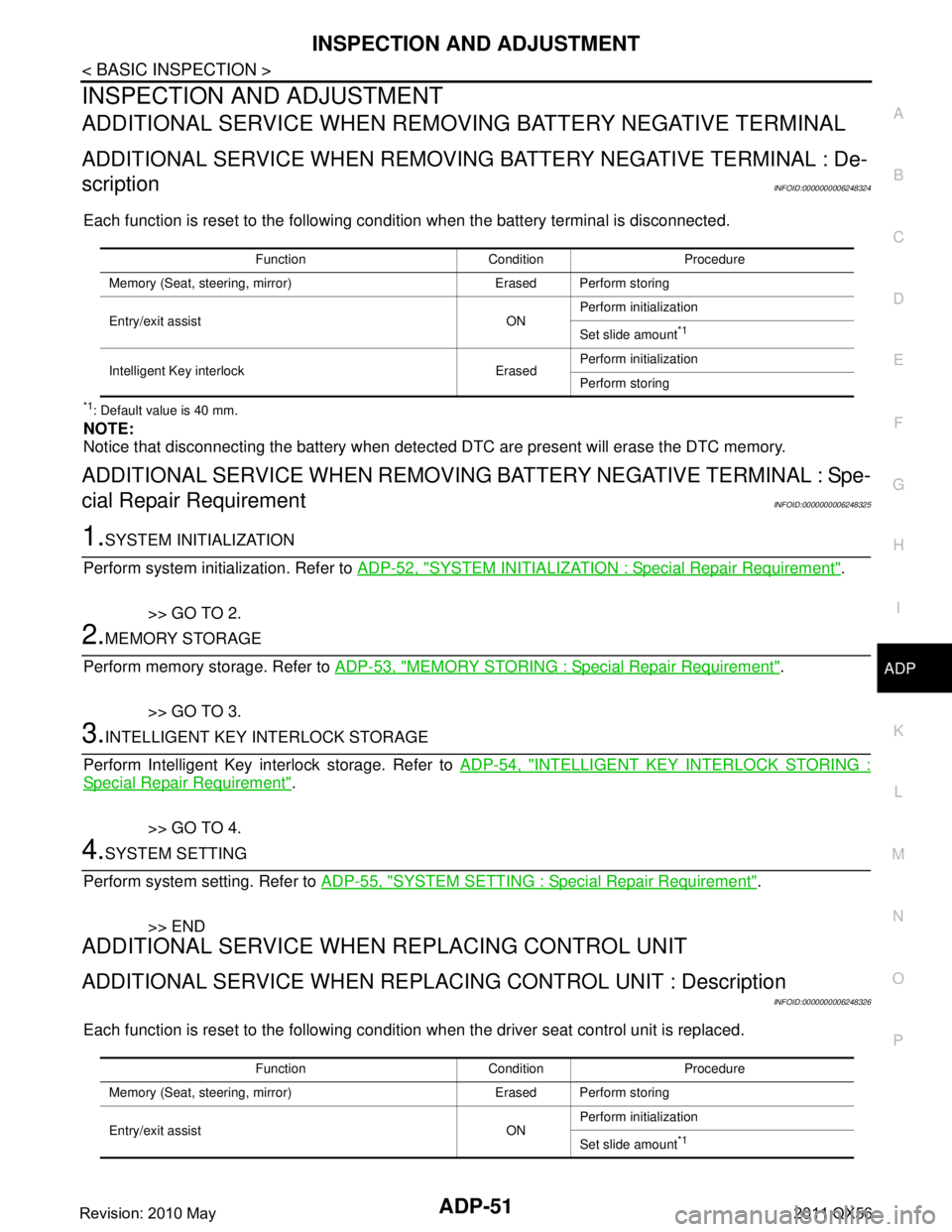
Each function is reset to the following condition when the battery terminal is disconnected.
*1: Default value is 40 mm.
NOTE:
Notice that disconnecting the battery when detect ed DTC are present will erase the DTC memory.
ADDITIONAL SERVICE WHEN REMOVING BATTERY NEGATIVE TERMINAL : Spe-
cial Repair Requirement
INFOID:0000000006248325
1.SYSTEM INITIALIZATION
Perform system initialization. Refer to ADP-52, "
SYSTEM INITIALIZATION : Special Repair Requirement".
>> GO TO 2.
2.MEMORY STORAGE
Perform memory storage. Refer to ADP-53, "
MEMORY STORING : Special Repair Requirement".
>> GO TO 3.
3.INTELLIGENT KEY INTERLOCK STORAGE
Perform Intelligent Key interlock storage. Refer to ADP-54, "
INTELLIGENT KEY INTERLOCK STORING :
Special Repair Requirement".
>> GO TO 4.
4.SYSTEM SETTING
Perform system setting. Refer to ADP-55, "
SYSTEM SETTING : Special Repair Requirement".
>> END
ADDITIONAL SERVICE WHEN REPLACING CONTROL UNIT
ADDITIONAL SERVICE WHEN REPL ACING CONTROL UNIT : Description
INFOID:0000000006248326
Each function is reset to the following condition when the driver seat control unit is replaced.
Function Condition Procedure
Memory (Seat, stee ring, mirror) Erased Perform storing
Entry/exit assist ON Perform initialization
Set slide amount
*1
Intelligent Key interlock Erased
Perform initialization
Perform storing
Function Condition Procedure
Memory (Seat, stee ring, mirror) Erased Perform storing
Entry/exit assist ON Perform initialization
Set slide amount
*1
Revision: 2010 May2011 QX56