check transmission fluid INFINITI QX56 2011 Factory Service Manual
[x] Cancel search | Manufacturer: INFINITI, Model Year: 2011, Model line: QX56, Model: INFINITI QX56 2011Pages: 5598, PDF Size: 94.53 MB
Page 1918 of 5598
![INFINITI QX56 2011 Factory Service Manual
DLN-116
< REMOVAL AND INSTALLATION >[TRANSFER: ATX90A]
TRANSFER HI-LO POSITION SENSOR
TRANSFER HI-LO POSITION SENSOR
Exploded ViewINFOID:0000000006222337
Removal and InstallationINFOID:00000000062223 INFINITI QX56 2011 Factory Service Manual
DLN-116
< REMOVAL AND INSTALLATION >[TRANSFER: ATX90A]
TRANSFER HI-LO POSITION SENSOR
TRANSFER HI-LO POSITION SENSOR
Exploded ViewINFOID:0000000006222337
Removal and InstallationINFOID:00000000062223](/img/42/57033/w960_57033-1917.png)
DLN-116
< REMOVAL AND INSTALLATION >[TRANSFER: ATX90A]
TRANSFER HI-LO POSITION SENSOR
TRANSFER HI-LO POSITION SENSOR
Exploded ViewINFOID:0000000006222337
Removal and InstallationINFOID:0000000006222338
REMOVAL
1. Turn the ignition switch OFF.
2. Disconnect negative battery terminal.
CAUTION:
Wait for 5 seconds after turn ing ignition switch OFF.
3. Remove exhaust front tube (LH). Refer to EX-5, "
Removal and Installation".
4. Support transfer assembly and transmission assembly with a jack.
5. Remove front suspension rear cross member with a power tool. Refer to TM-208, "
4WD : Removal and
Installation".
6. Remove rear engine mounting cross member with a power tool. Refer to TM-208, "
4WD : Removal and
Installation".
7. Remove heat insulator of exhaust front tube (LH).
8. Lower jack to the position where the tr ansfer Hi-Lo position sensor can be removed.
9. Disconnect the transfer Hi-Lo position sensor connector.
10. Remove the transfer Hi-Lo position sensor.
11. Perform inspection after removal. Refer to DLN-116, "
Inspection".
INSTALLATION
Note the following, and install in the reverse order of removal.
Never damage O-ring of transfer Hi-Lo position sensor.
Perform inspection after installation. Refer to DLN-116, "
Inspection".
InspectionINFOID:0000000006222339
INSPECTION AFTER REMOVAL
Check the O-ring assembled transfer Hi-Lo position sens or for wear, crack and damage. Replace the transfer
Hi-Lo position sensor if there is malfunction.
INSPECTION AFTER INSTALLATION
After driving, check the surface fitting transfer Hi-Lo position sensor to transfer assembly for fluid leakage.
1. Transfer Hi-Lo position sensor 2. Transfer assembly
: Vehicle front
Refer to GI-4, "
Components" for symbols not described above.
JPDIE0282GB
Revision: 2010 May2011 QX56
Page 1921 of 5598
![INFINITI QX56 2011 Factory Service Manual
TRANSFER LOCK POSITION SENSORDLN-119
< REMOVAL AND INSTALLATION > [TRANSFER: ATX90A]
C
EF
G H
I
J
K L
M A
B
DLN
N
O P
TRANSFER LOCK PO SITION SENSOR
Exploded ViewINFOID:0000000006222343
Removal and I INFINITI QX56 2011 Factory Service Manual
TRANSFER LOCK POSITION SENSORDLN-119
< REMOVAL AND INSTALLATION > [TRANSFER: ATX90A]
C
EF
G H
I
J
K L
M A
B
DLN
N
O P
TRANSFER LOCK PO SITION SENSOR
Exploded ViewINFOID:0000000006222343
Removal and I](/img/42/57033/w960_57033-1920.png)
TRANSFER LOCK POSITION SENSORDLN-119
< REMOVAL AND INSTALLATION > [TRANSFER: ATX90A]
C
EF
G H
I
J
K L
M A
B
DLN
N
O P
TRANSFER LOCK PO SITION SENSOR
Exploded ViewINFOID:0000000006222343
Removal and InstallationINFOID:0000000006222344
REMOVAL
1. Turn the ignition switch OFF.
2. Disconnect negative battery terminal.
CAUTION:
Wait for 5 seconds after turning ignition OFF.
3. Support transfer assembly and transmission assembly with a jack.
4. Remove rear engine mounting cross member with a power tool. Refer to TM-208, "
4WD : Removal and
Installation".
5. Lower jack to the position where the tr ansfer lock position sensor can be removed.
6. Disconnect the transfer lock position sensor connector.
7. Remove the transfer lock position sensor.
8. Perform inspection after removal. Refer to DLN-119, "
Inspection".
INSTALLATION
Note the following, and install in the reverse order of removal.
Never damage O-ring of transfer lock position sensor.
Perform inspection after installation. Refer to DLN-119, "
Inspection".
When replacing the transfer lock position sensor, perform learning of transfer lock position sensor. Refer to
DLN-44, "
Work Procedure".
InspectionINFOID:0000000006222345
INSPECTION AFTER REMOVAL
Check the O-ring assembled transfer lock position sensor for wear, crack and damage. Replace the transfer
lock position sensor if there is malfunction.
INSPECTION AFTER INSTALLATION
After driving, check the surface fitting transfer lock position sensor to transfer assembly for fluid leakage.
1. Transfer lock position sensor 2. Transfer assembly
: Vehicle front
Refer to GI-4, "
Components" for symbols not described above.
JPDIE0284GB
Revision: 2010 May2011 QX56
Page 1924 of 5598
![INFINITI QX56 2011 Factory Service Manual
DLN-122
< UNIT REMOVAL AND INSTALLATION >[TRANSFER: ATX90A]
TRANSFER ASSEMBLY
When installing the transfer to the
transmission, install the mount-
ing bolts following the standard below, tighten b INFINITI QX56 2011 Factory Service Manual
DLN-122
< UNIT REMOVAL AND INSTALLATION >[TRANSFER: ATX90A]
TRANSFER ASSEMBLY
When installing the transfer to the
transmission, install the mount-
ing bolts following the standard below, tighten b](/img/42/57033/w960_57033-1923.png)
DLN-122
< UNIT REMOVAL AND INSTALLATION >[TRANSFER: ATX90A]
TRANSFER ASSEMBLY
When installing the transfer to the
transmission, install the mount-
ing bolts following the standard below, tighten bolts to the specified
torque.
When installing transfer breather hose, make sure t here are no pinched or restricted areas on the transfer
breather hose caused by bending or winding.
- Install the transfer breather hose (1) of transmission side with the
paint mark (A) facing upward and the mark (B) (: ) facing right
side.
- Install the transfer breather hose (1) of transfer side with the paint mark (A) facing upward, and insert breather hose to breather tube
(2) until dimension (B) shown as follows.
- Be sure to fix breather hose in (A) and (B) positions. Fix with the
paint mark facing upward in the (A) position.
Check oil level and check for oil leakage after installation. Refer to DLN-106, "
Inspection".
If replacing transfer assembly, perform writing unit parameter,
learning of fluid viscosity and initial calibration. Refer to DLN-42,
"Work Procedure".
Bolt symbol A B
Insertion direction Transfer to transmission Transmission to transfer
: Tightening the bolt with bracket
JPDIE0259ZZ
JPDIE0247ZZ
B: 20 mm (0.79 in)
JPDIE0251ZZ
JPDIE0248ZZ
Revision: 2010 May2011 QX56
Page 2185 of 5598
![INFINITI QX56 2011 Factory Service Manual
TROUBLE DIAGNOSIS - SPECIFICATION VALUEEC-161
< DTC/CIRCUIT DIAGNOSIS > [VK56VD]
C
D
E
F
G H
I
J
K L
M A
EC
NP
O
DTC/CIRCUIT DIAGNOSIS
TROUBLE DIAGNOSIS - SPECIFICATION VALUE
DescriptionINFOID:000000 INFINITI QX56 2011 Factory Service Manual
TROUBLE DIAGNOSIS - SPECIFICATION VALUEEC-161
< DTC/CIRCUIT DIAGNOSIS > [VK56VD]
C
D
E
F
G H
I
J
K L
M A
EC
NP
O
DTC/CIRCUIT DIAGNOSIS
TROUBLE DIAGNOSIS - SPECIFICATION VALUE
DescriptionINFOID:000000](/img/42/57033/w960_57033-2184.png)
TROUBLE DIAGNOSIS - SPECIFICATION VALUEEC-161
< DTC/CIRCUIT DIAGNOSIS > [VK56VD]
C
D
E
F
G H
I
J
K L
M A
EC
NP
O
DTC/CIRCUIT DIAGNOSIS
TROUBLE DIAGNOSIS - SPECIFICATION VALUE
DescriptionINFOID:0000000006217760
The specification (SP) value indicates the tolerance of
the value that is displayed in “SPEC” in “DATA MONI-
TOR” mode of CONSULT-III during normal operation of the Engine Control System. When the value in “SPEC”
in “DATA MONITOR” mode is within the SP value, t he Engine Control System is confirmed OK. When the
value in “SPEC” in “DATA MONITOR” mode is NOT wit hin the SP value, the Engine Control System may have
one or more malfunctions.
The SP value is used to detect malfunctions that may affect the Engine Control System, but will not illuminate
the MIL.
The SP value will be displayed for the following items:
B/FUEL SCHDL (The fuel injection pulse width programmed into ECM prior to any learned on board correc- tion)
A/F ALPHA-B1/B2 (The mean value of air-fuel ratio feedback correction factor per cycle)
MAS A/F SE-B1/B2 (The signal voltage of the mass air flow sensor)
IDLE FUEL PRES MAX/MIN (the signal voltage of the fuel rail pressure sensor)
Component Function CheckINFOID:0000000006217761
1.PRECONDITIONING
Check that all of the following conditions are satisfied.
TESTING CONDITION
Vehicle driven distance: More than 5,000 km (3,107 miles)
Barometric pressure: 98.3 - 104.3 kPa (0.983 - 1.043 bar, 1.003 - 1.064 kg/cm
2, 14.25 - 15.12 psi)
Atmospheric temperature: 20 - 30 °C (68 - 86 °F)
Engine coolant temperature: 75 - 95 °C (167 - 203 °F)
Transmission: Warmed-up
- After the engine is warmed up to normal operating temperat ure, drive vehicle until “ATF TEMP 2” (A/T fluid
temperature sensor signal) indicates more than 60 °C (140 °F).
Electrical load: Not applied
- Rear window defogger switch, air conditioner switch and li ghting switch are OFF. Steering wheel is straight
ahead.
Engine speed: Idle
Gear position: Neutral ( or parking)
>> GO TO 2.
2.PERFORM SPEC IN DATA MONITOR MODE
WITH CONSULT-III
NOTE:
Perform “SPEC” in “DATA MONITOR” mode in maximum scale display.
1. Perform EC-139, "
Work Procedure".
2. Select “B/FUEL SCHDL”, “A/F ALPHA-B1”, “A/F ALPHA-B2”, “MAS A/F SE-B1” in “SPEC” of “DATA
MONITOR” mode with CONSULT-III.
3. Check that monitor items are within the SP value.
Is the measurement value within the SP value?
YES >> INSPECTION END
NO >> Proceed to EC-162, "
Diagnosis Procedure".
Revision: 2010 May2011 QX56
Page 2635 of 5598
TIMING CHAINEM-73
< REMOVAL AND INSTALLATION >
C
DE
F
G H
I
J
K L
M A
EM
NP
O
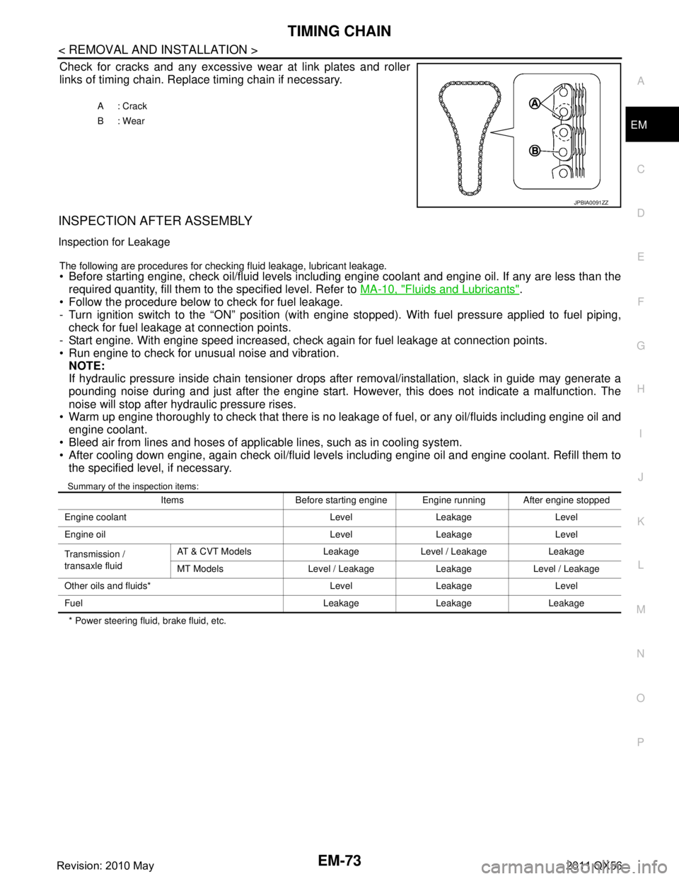
Check for cracks and any excessive
wear at link plates and roller
links of timing chain. Replace timing chain if necessary.
INSPECTION AFTER ASSEMBLY
Inspection for Leakage
The following are procedures for chec king fluid leakage, lubricant leakage. Before starting engine, check oil/fluid levels including engine coolant and engine oil. If any are less than the
required quantity, fill them to the specified level. Refer to MA-10, "
Fluids and Lubricants".
Follow the procedure below to check for fuel leakage.
- Turn ignition switch to the “ON” position (with engi ne stopped). With fuel pressure applied to fuel piping,
check for fuel leakage at connection points.
- Start engine. With engine speed increased, check again for fuel leakage at connection points.
Run engine to check for unusual noise and vibration.
NOTE:
If hydraulic pressure inside chain tensioner drops after removal/installation, slack in guide may generate a
pounding noise during and just after the engine start. However, this does not indicate a malfunction. The
noise will stop after hydraulic pressure rises.
Warm up engine thoroughly to check that there is no leak age of fuel, or any oil/fluids including engine oil and
engine coolant.
Bleed air from lines and hoses of applicable lines, such as in cooling system.
After cooling down engine, again check oil/fluid levels including engine oil and engine coolant. Refill them to the specified level, if necessary.
Summary of the inspection items:
* Power steering fluid, brake fluid, etc. A: Crack
B: Wear
JPBIA0091ZZ
Items Before starting engine Engine running After engine stopped
Engine coolant Level Leakage Level
Engine oil Level Leakage Level
Transmission /
transaxle fluid AT & CVT Models Leakage Level / Leakage Leakage
MT Models Level / Leakage Leakage Level / Leakage
Other oils and fluids* Level Leakage Level
Fuel Leakage Leakage Leakage
Revision: 2010 May2011 QX56
Page 2647 of 5598
CAMSHAFTEM-85
< REMOVAL AND INSTALLATION >
C
DE
F
G H
I
J
K L
M A
EM
NP
O
5. Perform the following inspection if engine oil does not
come out from valve timing control solenoid valve
oil hole of the valve timing control cover.
Remove oil filter, and then clean it. Refer to EM-61, "
Exploded View".
Clean oil groove between oil strainer and valve timing control solenoid valve. Refer to LU-5, "
Engine
Lubrication System" and LU-6, "Engine Lubrication System Schematic".
6. Remove components between valve timing control solenoid valve and camshaft sprocket, and then check each oil groove for clogging.
Clean oil groove if necessary. Refer to LU-5, "
Engine Lubrication System" and LU-6, "Engine Lubrica-
tion System Schematic".
7. After inspection, install removed parts in the reverse order.
Inspection for Leakage
The following are procedures for chec king fluid leakage, lubricant leakage.
Before starting engine, check oil/fluid levels including engine coolant and engine oil. If any are less than the
required quantity, fill them to the specified level. Refer to MA-10, "
Fluids and Lubricants".
Follow the procedure below to check for fuel leakage.
- Turn ignition switch to the “ON” position (with engi ne stopped). With fuel pressure applied to fuel piping,
check for fuel leakage at connection points.
- Start engine. With engine speed increased, check again for fuel leakage at connection points.
Run engine to check for unusual noise and vibration. NOTE:
If hydraulic pressure inside chain tensioner drops after removal/installation, slack in guide may generate a
pounding noise during and just after the engine start. However, this does not indicate a malfunction. The
noise will stop after hydraulic pressure rises.
Warm up engine thoroughly to check that there is no leak age of fuel, or any oil/fluids including engine oil and
engine coolant.
Bleed air from lines and hoses of applicable lines, such as in cooling system.
After cooling down engine, again check oil/fluid levels including engine oil and engine coolant. Refill them to
the specified level, if necessary.
Summary of the inspection items:
* Power steering fluid, brake fluid, etc. Items Before starting engine Engine running After engine stopped
Engine coolant Level Leakage Level
Engine oil Level Leakage Level
Transmission /
transaxle fluid AT & CVT Models Leakage Level / Leakage Leakage
MT Models Level / Leakage Leakage Level / Leakage
Other oils and fluids* Level Leakage Level
Fuel Leakage Leakage Leakage
Revision: 2010 May2011 QX56
Page 2657 of 5598
CYLINDER HEADEM-95
< REMOVAL AND INSTALLATION >
C
DE
F
G H
I
J
K L
M A
EM
NP
O
If hydraulic pressure inside chain tensioner drops after removal/installation, slack in guide may generate a
pounding noise during and just after the engine start. However, this does not indicate a malfunction. The
noise will stop after hydraulic pressure rises.
Warm up engine thoroughly to check that there is no leak age of fuel, or any oil/fluids including engine oil and
engine coolant.
Bleed air from lines and hoses of applicable lines, such as in cooling system.
After cooling down engine, again check oil/fluid levels including engine oil and engine coolant. Refill them to
the specified level, if necessary.
Summary of the inspection items:
* Power steering fluid, brake fluid, etc. Items Before starting engine Engine running After engine stopped
Engine coolant Level Leakage Level
Engine oil Level Leakage Level
Transmission /
transaxle fluid AT & CVT Models Leakage Level / Leakage Leakage
MT Models Level / Leakage Leakage Level / Leakage
Other oils and fluids* Level Leakage Level
Fuel Leakage Leakage Leakage
Revision: 2010 May2011 QX56
Page 2664 of 5598
EM-102
< UNIT REMOVAL AND INSTALLATION >
ENGINE ASSEMBLY
INSTALLATION
Install in the reverse order of removal.
CAUTION:
When replacing an engine or transmission you must make sure the dowels are installed correctly
during re-assembly.Improper alignment caused by mi ssing dowels may cause vibration, oil leaks or
breakage of drivetrain components.
InspectionINFOID:0000000006289578
INSPECTION AFTER INSTALLATION
Inspection for Leakage
The following are procedures for checking fluid leakage, lubricant leakage. Before starting engine, check oil/fluid levels includi ng engine coolant and engine oil. If any are less than the
required quantity, fill them to the specified level. Refer to MA-10, "
Fluids and Lubricants".
Follow the procedure below to check for fuel leakage.
- Turn ignition switch to the “ON” position (with engi ne stopped). With fuel pressure applied to fuel piping,
check for fuel leakage at connection points.
- Start engine. With engine speed increased, che ck again for fuel leakage at connection points.
Run engine to check for unusual noise and vibration. NOTE:
If hydraulic pressure inside chain tensioner drops af ter removal/installation, slack in guide may generate a
pounding noise during and just after the engine start. However, this does not indicate a malfunction. The
noise will stop after hydraulic pressure rises.
Warm up engine thoroughly to check that there is no leak age of fuel, or any oil/fluids including engine oil and
engine coolant.
Bleed air from lines and hoses of applic able lines, such as in cooling system.
After cooling down engine, again check oil/fluid levels including engine oil and engine coolant. Refill them to
the specified level, if necessary.
Summary of the inspection items:
*: Power steering fluid, brake fluid, etc. Items Before starting engine Engine running After engine stopped
Engine coolant Level Leakage Level
Engine oil Level Leakage Level
Transmission /
transaxle fluid AT & CVT Models Leakage Level / Leakage Leakage
MT Models Level / Leakage Leakage Level / Leakage
Other oils and fluids* Level Leakage Level
Fuel Leakage Leakage Leakage
Exhaust gases — Leakage —
Revision: 2010 May2011 QX56
Page 2992 of 5598
GI-28
< PRECAUTION >
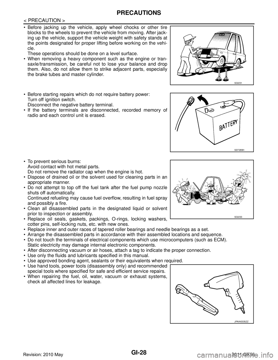
PRECAUTIONS
Before jacking up the vehicle, apply wheel chocks or other tireblocks to the wheels to prevent t he vehicle from moving. After jack-
ing up the vehicle, support the vehicle weight with safety stands at
the points designated for proper lifting before working on the vehi-
cle.
These operations should be done on a level surface.
When removing a heavy component such as the engine or tran- saxle/transmission, be careful not to lose your balance and drop
them. Also, do not allow them to strike adjacent parts, especially
the brake tubes and master cylinder.
Before starting repairs which do not require battery power: Turn off ignition switch.
Disconnect the negative battery terminal.
If the battery terminals are disconnected, recorded memory of
radio and each control unit is erased.
To prevent serious burns: Avoid contact with hot metal parts.
Do not remove the radiator cap when the engine is hot.
Dispose of drained oil or the solvent used for cleaning parts in an appropriate manner.
Do not attempt to top off the fuel tank after the fuel pump nozzle
shuts off automatically.
Continued refueling may cause fuel overflow, resulting in fuel spray
and possibly a fire.
Clean all disassembled parts in the designated liquid or solvent prior to inspection or assembly.
Replace oil seals, gaskets, packings, O-rings, locking washers,
cotter pins, self-locking nuts, etc. with new ones.
Replace inner and outer races of tapered roller bearings and needle bearings as a set.
Arrange the disassembled parts in accordance with their assembled locations and sequence.
Do not touch the terminals of electrical com ponents which use microcomputers (such as ECM).
Static electricity may damage internal electronic components.
After disconnecting vacuum or air hoses, atta ch a tag to indicate the proper connection.
Use only the fluids and lubricants specified in this manual.
Use approved bonding agent, sealants or their equivalents when required.
Use hand tools, power tools (disassembly only) and recommended special tools where specified for safe and efficient service repairs.
When repairing the fuel, oil, water, vacuum or exhaust systems, check all affected lines for leakage.
SGI231
SEF289H
SGI233
JPAIA0335ZZ
Revision: 2010 May2011 QX56
Page 5089 of 5598
TM-1
TRANSMISSION & DRIVELINE
CEF
G H
I
J
K L
M
SECTION TM
A
B
TM
N
O P
CONTENTS
TRANSAXLE & TRANSMISSION
7AT: RE7R01B
PRECAUTION ................ ...............................
6
PRECAUTIONS .............................................. .....6
Precaution for Supplemental Restraint System
(SRS) "AIR BAG" and "SEAT BELT PRE-TEN-
SIONER" ............................................................. ......
6
General Precautions .................................................6
Service Notice or Precaution .....................................7
PREPARATION ............................................8
PREPARATION .............................................. .....8
Special Service Tool ........................................... ......8
Commercial Service Tool ..........................................9
SYSTEM DESCRIPTION .............................10
COMPONENT PARTS ................................... ....10
A/T CONTROL SYSTEM ...........................................10
A/T CONTROL SYSTEM : Component Parts Lo-
cation ................................................................... ....
10
A/T CONTROL SYSTEM : Component Descrip-
tion ...................................................................... ....
11
A/T CONTROL SYSTEM : TCM .............................12
A/T CONTROL SYSTEM : Transmission Range
Switch .................................................................. ....
12
A/T CONTROL SYSTEM : Input Speed Sensor .....12
A/T CONTROL SYSTEM : Output Speed Sensor ....12
A/T CONTROL SYSTEM : A/ T Fluid Temperature
Sensor ................................................................. ....
12
A/T CONTROL SYSTEM : Input Clutch Solenoid
Valve ................................................................... ....
12
A/T CONTROL SYSTEM : Front Brake Solenoid
Valve ................................................................... ....
12
A/T CONTROL SYSTEM : Direct Clutch Solenoid
Valve ................................................................... ....
12
A/T CONTROL SYSTEM : High and Low Reverse
Clutch Solenoid Valve ......................................... ....
13
A/T CONTROL SYSTEM : Low Brake Solenoid
Valve .................................................................... ....
13
A/T CONTROL SYSTEM : Anti-interlock Solenoid
Valve ........................................................................
13
A/T CONTROL SYSTEM : 2346 Brake Solenoid
Valve ........................................................................
13
A/T CONTROL SYSTEM : Torque Converter
Clutch Solenoid Valve ......................................... ....
13
A/T CONTROL SYSTEM : Line Pressure Solenoid
Valve .................................................................... ....
13
A/T CONTROL SYSTEM : Accelerator Pedal Po-
sition Sensor ........................................................ ....
13
A/T CONTROL SYSTEM : Manual Mode Switch ....13
A/T CONTROL SYSTEM : To w Mode Switch .........14
A/T CONTROL SYSTEM : A/T CHECK Indicator
Lamp .................................................................... ....
14
A/T CONTROL SYSTEM : Tow Mode Indicator
Lamp .................................................................... ....
14
A/T CONTROL SYSTEM : Selector Lever Position
Indicator ............................................................... ....
14
A/T SHIFT LOCK SYSTEM ................................... ....14
A/T SHIFT LOCK SYSTEM : Component Parts
Location ...................................................................
15
A/T SHIFT LOCK SYSTEM : Component Descrip-
tion ...........................................................................
15
STRUCTURE AND OPERATION .....................16
TRANSMISSION .................................................... ....16
TRANSMISSION : Cross-Sectional View ................16
TRANSMISSION : System Diagram ........................18
TRANSMISSION : System Description ...................18
TRANSMISSION : Component Description .............41
FLUID COOLER & FLUID WARMER SYSTEM .... ....41
FLUID COOLER & FLUID WARMER SYSTEM :
System Description ..................................................
41
SYSTEM ............................................................44
A/T CONTROL SYSTEM ....................................... ....44
Revision: 2010 May2011 QX56