oil INFINITI QX56 2011 Factory Service Manual
[x] Cancel search | Manufacturer: INFINITI, Model Year: 2011, Model line: QX56, Model: INFINITI QX56 2011Pages: 5598, PDF Size: 94.53 MB
Page 5 of 5598

QUICK REFERENCE CHART QX56
BRAKE PEDAL
Unit : mm (in)
FRONT DISK BRAKE
Unit : mm (in)
REAR DISK BRAKE
Unit : mm (in)
REFILL CAPACITIESELS00040
Item Standard
Brake pedal height 168.5 (6.63) – 178.5 (7.03)
Depressed brake pedal height
[Depressing 490 N (50 kg, 110 lb) while turning the engine ON] 100 (3.94) or more
Item Limit
Brake pad Wear thickness 1.5 (0.059)
Disc rotor Wear thickness 28.5 (1.122)
Thickness variation (measured at 8 positions) 0.015 (0.0006)
Runout (with it attached to the vehicle) 0.053 (0.0021)
Item Limit
Brake pad Wear thickness 2.0 (0.079)
Disc rotor Wear thickness 18.0 (0.709)
Thickness variation (measured at 8 positions) 0.015 (0.0006)
Runout (with it attached to the vehicle) 0.05 (0.0020)
UNIT
Liter US measure
Fuel tank 98.4 26 gal
Engine Coolant ( With reservoir tank ) at MAX level 14.9 15-6/8 qt
Engine oil Drain and refill
With oil filter change 6.5 6-7/8 qt
Without oil filter change 6.2 6-4/8 qt
Dry engine (Overhaul) 7.6 8 qt
Transmission 10.0 10-5/8 qt
Transfer 1.5 3-1/8 pt
Final drive Front 0.75 1-5/8 pt
Rear 1.75 3-3/4 pt
Power steering system 1.0 7/8 qt
Air conditioning system Compressor oil 0.21 7.1 fl oz
Refrigerant 1.05 kg 2.32 lb
2011
Page 398 of 5598

BCS-10
< SYSTEM DESCRIPTION >
SYSTEM
NOTE:
For details of wiper volume dial position, refer to WW-7, "
FRONT WIPER AND WASHER SYSTEM : System Description".
SIGNAL BUFFER SYSTEM
SIGNAL BUFFER SYSTEM : System DiagramINFOID:0000000006274792
SIGNAL BUFFER SYSTEM : System DescriptionINFOID:0000000006274793
OUTLINE
BCM has the signal transmission function that output s/transmits each input/received signal to each unit.
Signal transmission function list
6 OFF ON ON
7 OFF ON OFF
Wiper volume
dial position Switch status
WIP VOLUME 1 WIP VOLUME 2 WIP VOLUME 3
JMMIA0381GB
Signal name Input Output Description
Ignition switch ON signal
Ignition switch signal Push-button ignition switch
(Push switch) IPDM E/R (CAN)
Driver seat control unit (CAN)
Pre-crash seat
belt control
unit (CAN) Inputs the push-button ignition
switch (push switch) signal and
transmits the ignition switch sta-
tus judged with BCM via CAN
communication.
Door switch signal Any door switch Combination meter (CAN)
IPDM E/R (CAN)
Driver seat control unit (CAN)
Pre-crash seat
belt control
unit (CAN) Inputs the door switch signal
and transmits it via CAN com-
munication.
Oil pressure switch signal IPDM E/R (CAN) Combination meter (CAN) Transmits the received oil pres-
sure switch signal via CAN
communication.
Revision: 2010 May2011 QX56
Page 420 of 5598

BCS-32
< SYSTEM DESCRIPTION >
DIAGNOSIS SYSTEM (BCM)
ACTIVE TEST
Te s t i t e mOpera-
tion Description
OIL PRESSURE SW Off OFF
On
BCM transmits the oil pressure switch signal to the combination meter via CAN communica-
tion, which illuminates the oil pressure warning lamp in the combination meter.
Revision: 2010 May2011 QX56
Page 474 of 5598

BR-4
< PRECAUTION >
PRECAUTIONS
5. When the repair work is completed, re-connect both battery cables. With the brake pedal released, turn
the push-button ignition switch from ACC position to ON position, then to LOCK position. (The steering
wheel will lock when the push-button igniti on switch is turned to LOCK position.)
6. Perform self-diagnosis check of all control units using CONSULT-III.
Precaution for Procedure without Cowl Top CoverINFOID:0000000006228173
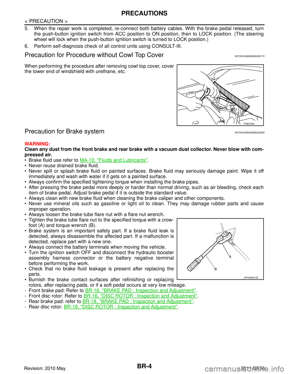
When performing the procedure after removing cowl top cover, cover
the lower end of windshield with urethane, etc.
Precaution for Brake systemINFOID:0000000006222459
WARNING:
Clean any dust from the front brake and rear brake wi th a vacuum dust collector. Never blow with com-
pressed air.
Brake fluid use refer to MA-10, "
Fluids and Lubricants".
Never reuse drained brake fluid.
Never spill or splash brake fluid on painted surfaces. Brake fluid may seriously damage paint. Wipe it off
immediately and wash with water if it gets on a painted surface.
Always confirm the specified tightening torque when installing the brake pipes.
After pressing the brake pedal more deeply or harder t han normal driving, such as air bleeding, check each
item of brake pedal. Adjust brake pedal if it is outside the standard value.
Always clean with new brake fluid when cleaning the brake caliper and other components.
Never use mineral oils such as gasoline or light oil to clean. They may damage rubber parts and cause
improper operation.
Always loosen the brake tube flar e nut with a flare nut wrench.
Tighten the brake tube flare nut to the specified torque with a crow-
foot (A) and torque wrench (B).
Brake system is an important safety part. If a brake fluid leak is detected, always disassemble the affected part. If a malfunction is
detected, replace part with a new one.
Always connect the battery terminals when moving the vehicle.
Turn the ignition switch OFF and disconnect the hydraulic booster assembly harness connector or the battery negative terminal
before performing the work.
Check that no brake fluid leakage is present after replacing the
parts.
Burnish the brake contact surfaces after refinishing or replacing rotors, after replacing pads, or if a soft pedal occurs at very low mileage.
- Front brake pad: Refer to BR-16, "
BRAKE PAD : Inspection and Adjustment".
- Front disc rotor: Refer to BR-16, "
DISC ROTOR : Inspection and Adjustment".
- Rear brake pad: refer to BR-18, "
BRAKE PAD : Inspection and Adjustment".
- Rear disc rotor: BR-18, "
DISC ROTOR : Inspection and Adjustment".
PIIB3706J
JPFIA0001ZZ
Revision: 2010 May2011 QX56
Page 480 of 5598

BR-10
< PERIODIC MAINTENANCE >
BRAKE FLUID
BRAKE FLUID
InspectionINFOID:0000000006222463
BRAKE FLUID LEVEL
Check that the fluid level in the reservoir tank is within the specified range (MAX – MIN lines).
CAUTION:
Turn OFF the ignition switch an d depress the brake pedal 20 times or more to check brake fluid level.
NOTE:
Since brake fluid is in the accumulator in pressurized condition, the reservoir tank brake fluid level should be
lower than the MAX line.
Visually check for any brake fluid leakage around the reservoir tank.
Check the brake system for any leakage if the fl uid level is extremely low (lower than MIN).
Check the brake system for fluid leakage if the warn ing lamp remains illuminated even after the parking
brake is released.
Check the reservoir tank for the mixing of foreign matter (e.g. dust) and oils other than brake fluid.
BRAKE LINE
1. Check brake line (tubes and hoses) for cracks, deterioration or other damage. Replace any damaged
parts.
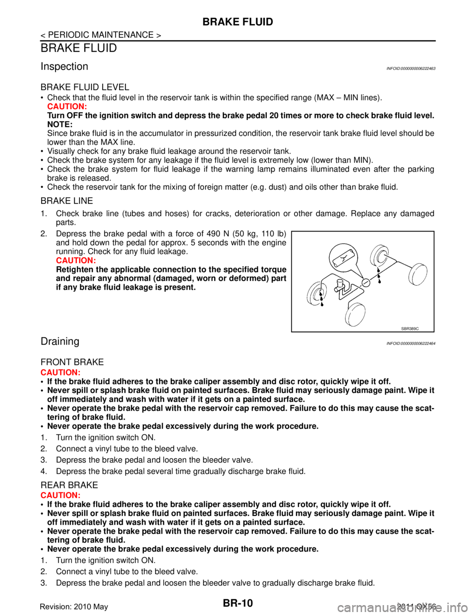
2. Depress the brake pedal with a force of 490 N (50 kg, 110 lb) and hold down the pedal for approx. 5 seconds with the engine
running. Check for any fluid leakage.
CAUTION:
Retighten the applicable conn ection to the specified torque
and repair any abnormal (damag ed, worn or deformed) part
if any brake fluid leakage is present.
DrainingINFOID:0000000006222464
FRONT BRAKE
CAUTION:
If the brake fluid adheres to the brake caliper assembly and disc rotor, quickly wipe it off.
Never spill or splash brake fluid on painted surfaces. Brake fluid may seriously damage paint. Wipe it
off immediately and wash with wate r if it gets on a painted surface.
Never operate the brake pedal with the reservoir cap removed. Failure to do this may cause the scat-
tering of brake fluid.
Never operate the brake pedal excessively during the work procedure.
1. Turn the ignition switch ON.
2. Connect a vinyl tube to the bleed valve.
3. Depress the brake pedal and loosen the bleeder valve.
4. Depress the brake pedal several time gradually discharge brake fluid.
REAR BRAKE
CAUTION:
If the brake fluid adheres to the brake caliper assembly and disc rotor, quickly wipe it off.
Never spill or splash brake fluid on painted surfaces. Brake fluid may seriously damage paint. Wipe it
off immediately and wash with wate r if it gets on a painted surface.
Never operate the brake pedal with the reservoir cap removed. Failure to do this may cause the scat- tering of brake fluid.
Never operate the brake pedal excessively during the work procedure.
1. Turn the ignition switch ON.
2. Connect a vinyl tube to the bleed valve.
3. Depress the brake pedal and loosen the bleeder valve to gradually discharge brake fluid.
SBR389C
Revision: 2010 May2011 QX56
Page 481 of 5598

BRAKE FLUIDBR-11
< PERIODIC MAINTENANCE >
C
DE
G H
I
J
K L
M A
B
BR
N
O P
NOTE:
Since brake fluid is conveyed by the motor, the brake pedal is not necessarily depressed.
RefillingINFOID:0000000006222465
FRONT BRAKE
CAUTION:
If the brake fluid adheres to the brake caliper assembly and disc rotor, quickly wipe it off.
Never spill or splash brake fluid on painted surfaces. Brake fluid may seriously damage paint. Wipe it
off immediately and wash with wate r if it gets on a painted surface.
Never operate the brake pedal with the reservoir cap removed. Failure to do this may cause the scat-
tering of brake fluid.
Never operate the brake pedal excessively during the work procedure.
Monitor the fluid level in the reservoir tank while performing the refilling.
1. Check that there is no foreign material in t he reservoir tank, and refill with new brake fluid.
CAUTION:
Never reuse drained brake fluid.
Never allow oils other than brake fl uid to enter the reservoir tank.
2. Turn the ignition switch ON.
3. Connect a vinyl tube to the bleed valve.
4. Depress the brake pedal and loosen the bleeder valve.
5. Depress the brake pedal several times until the re filled brake fluid is discharged and tighten the air
bleeder to the specified torque with the brake pedal depressed. Refer to BR-36, "
BRAKE CALIPER
ASSEMBLY : Exploded View".
6. Perform the air bleeding. Refer to BR-11, "
Bleeding Brake System".
REAR BRAKE
CAUTION:
If the brake fluid adheres to the brake caliper assembly and disc rotor, quickly wipe it off.
Never spill or splash brake fluid on painted surfaces. Brake fluid may seriously damage paint. Wipe it
off immediately and wash with wate r if it gets on a painted surface.
Never operate the brake pedal with the reservoir cap removed. Failure to do this may cause the scat-
tering of brake fluid.
Never operate the brake pedal excessively during the work procedure.
Monitor the fluid level in the reservoir tank while performing the refilling.
1. Check that there is no foreign material in t he reservoir tank, and refill with new brake fluid.
CAUTION:
Never reuse drained brake fluid.
Never allow oils other than brake fl uid to enter the reservoir tank.
2. Turn the ignition switch ON.
3. Connect a vinyl tube to the bleed valve.
4. Depress the brake pedal and loosen the bleeder valve.
5. Depress the brake pedal several times until the re filled brake fluid is discharged and tighten the air
bleeder to the specified torque with the brake pedal depressed. Refer to BR-42, "
BRAKE CALIPER
ASSEMBLY : Exploded View".
NOTE:
Since brake fluid is conveyed by the motor, the brake pedal is not necessarily depressed.
6. Perform the air bleeding. Refer to BR-11, "
Bleeding Brake System".
Bleeding Brake SystemINFOID:0000000006222466
CAUTION:
Bleed air in the following order: motor/accumulator assembly → front right brake → front left brake
→ rear left brake → and rear right brake.
The VDC warning lamp, ABS warning lamp and br ake warning lamp turn ON and DTC “C118E” may
be detected in self-diagnosis result for “ABS” with CONSULT-III when the brake pedal is excessively
operated, such as air bleeding. This is not a system malfunction because this occurs due to the tem-
porary decrease in accumulator fl uid pressure. The system returns to normal condition when the
accumulator fluid pressure reaches the specified pressu re with the ignition switch ON and the VDC
Revision: 2010 May2011 QX56
Page 482 of 5598

BR-12
< PERIODIC MAINTENANCE >
BRAKE FLUID
warning lamp, ABS warning lamp, and brake warning lamp turn OFF. After these steps, erase self-
diagnosis results for “ABS” with CONSULT-III.
- DTC other than “C118E” is detected: Refer to BRC-51, "
DTC Index".
NOTE:
When the ignition switch is ON, the brake warning la mp may turns ON even when the parking brake pedal is
released with the brake fluid within the specified level. This indicates the decrease in accumulator fluid pres-
sure.
MOTOR/ACCUMULATOR ASSEMBLY
CAUTION:
If the brake fluid adheres to the brake caliper assembly and disc rotor, quickly wipe it off.
Never spill or splash brake fluid on painted surfaces. Brake fluid may seriously damage paint. Wipe it
off immediately and wash with wate r if it gets on a painted surface.
Never operate the brake pedal with the reservoir cap removed. Failure to do this may cause the scat-
tering of brake fluid.
Never operate the brake pedal excessively during the work procedure.
Monitor the fluid level in the reservoir tank while performing the air bleeding.
Bleed air in the following order: motor/accumulator assembly → front right brake → front left brake
→ rear left brake → and rear right brake.
1. Turn the ignition switch OFF.
2. Depress the brake pedal 20 times or more.
3. Check that there is no foreign material in the reservoir tank, and refill with new brake fluid. CAUTION:
Never reuse drained brake fluid.
Never allow oils other than brake fluid to enter the reservoir tank.
4. Turn the ignition switch ON. NOTE:
The motor is activated and automatically stops.
5. Turn the ignition switch OFF.
6. Depress the brake pedal 20 times or more. NOTE:
The pressure loss in the accumulator results in a large brake pedal stroke. In addition to this, the brake
pedal depression becomes lighter in initial stage.
7. Repeat steps 4 to 6 for 5 times.
8. Turn the ignition switch ON to check that the time between motor activation and automatic stop is less
than 18 seconds. If the time is 18 seconds or more, repeat from Step 4 to 8.
FRONT BRAKE
CAUTION:
If the brake fluid adheres to the brake caliper assembly and disc rotor, quickly wipe it off.
Never spill or splash brake fluid on painted surfaces. Brake fluid may seriously damage paint. Wipe it
off immediately and wash with wate r if it gets on a painted surface.
Never operate the brake pedal with the reservoir cap removed. Failure to do this may cause the scat- tering of brake fluid.
Never operate the brake pedal excessively during the work procedure.
Monitor the fluid level in the reservoir tank while performing the air bleeding.
Bleed air in the following order: motor/accumulator assembly → front right brake → front left brake
→ rear left brake → and rear right brake.
1. Turn the ignition switch OFF.
2. Depress the brake pedal 20 times or more. NOTE:
The pressure loss in the accumulator results in a large brake pedal stroke. In addition to this, the brake
pedal depression becomes lighter in initial stage.
3. Check that there is no foreign material in the reservoir tank, and refill with new brake fluid. CAUTION:
Never reuse drained brake fluid.
Never allow oils other than brake fluid to enter the reservoir tank.
4. Turn the ignition switch ON.
Revision: 2010 May2011 QX56
Page 483 of 5598

BRAKE FLUIDBR-13
< PERIODIC MAINTENANCE >
C
DE
G H
I
J
K L
M A
B
BR
N
O P
5. Connect a vinyl tube to the bleed valve.
6. Depress the brake pedal and loosen the bleeder valve.
7. Repeat steps 1 to 6 until all of the air is out of the brake line and tighten the air bleeder to the specified
torque with the brake pedal depressed. Refer to BR-36, "
BRAKE CALIPER ASSEMBLY : Exploded View".
8. Check that no drag feel is present for the front disc brake. Refer to BR-39, "
BRAKE CALIPER ASSEMBLY
: Inspection".
9. Check each item of brake pedal. Adjust it if t he measurement value is not the standard. Refer to BR-7,
"Inspection and Adjustment".
REAR BRAKE
CAUTION:
If the brake fluid adheres to the brake caliper assembly and disc rotor, quickly wipe it off.
Never spill or splash brake fluid on painted surfaces. Brake fluid may seriously damage paint. Wipe it
off immediately and wash with wate r if it gets on a painted surface.
Never operate the brake pedal with the reservoir cap removed. Failure to do this may cause the scat-
tering of brake fluid.
Never operate the brake pedal excessively during the work procedure.
Monitor the fluid level in the reservoir tank while performing the air bleeding.
Bleed air in the following order: motor/accumulator assembly → front right brake → front left brake
→ rear left brake → and rear right brake.
1. Turn the ignition switch OFF.
2. Depress the brake pedal 20 times or more. NOTE:
The pressure loss in the accumulator results in a large brake pedal stroke. In addition to this, the brake
pedal depression becomes lighter in initial stage.
3. Check that there is no foreign material in t he reservoir tank, and refill with new brake fluid.
CAUTION:
Never reuse drained brake fluid.
Never allow oils other than brake fl uid to enter the reservoir tank.
4. Turn the ignition switch ON.
5. Connect a vinyl tube to the bleed valve.
6. Depress the brake pedal and loosen the bleeder valve.
7. Depress and hold the brake pedal depression to disc harge 100 cc of brake fluid before tightening the air
bleeder to the specified torque. Refer to BR-42, "
BRAKE CALIPER ASSEMBLY : Exploded View".
NOTE:
Since brake fluid is conveyed by the motor, the brake pedal is not necessarily depressed.
8. Release the brake pedal.
9. Repeat steps 1 to 8 until all of the air is out of the brake line and tighten the air bleeder to the specified
torque with the brake pedal depressed. Refer to BR-42, "
BRAKE CALIPER ASSEMBLY : Exploded View".
10. Check that no drag feel is present for the rear disc brake. Refer to BR-45, "
BRAKE CALIPER ASSEMBLY
: Inspection".
11. Check each item of brake pedal. Adjust it if t he measurement value is not the standard. Refer to BR-7,
"Inspection and Adjustment".
BRAKE FLUID LEVEL ADJUSTMENT AFTER AIR BLEEDING
1. Turn the ignition switch OFF.
2. Depress the brake pedal 20 times or more.
NOTE:
The pressure loss in the accumulator results in a large brake pedal stroke. In addition to this, the brake
pedal depression becomes lighter in initial stage.
Revision: 2010 May2011 QX56
Page 501 of 5598

HYDRAULIC BOOSTER ASSEMBLYBR-31
< REMOVAL AND INSTALLATION >
C
DE
G H
I
J
K L
M A
B
BR
N
O P
2. Remove the reservoir tank mounting pin with a pin punch (com- mercial service tool).
3. Remove bolt and remove the reservoir tank and grommets from the ABS actuator and electric unit (control unit).
CAUTION:
Never drop the removed parts. The parts must not be
reused if they are dropped.
4. Slide the clamp and remove brake hose assembly.
5. Remove the brake tube with a flare nut wrench. CAUTION:
Never scratch the flare nut and the brake tube.
6. Remove the cap with a suitable tool (A).
7. Remove grommets and screws ( ) and remove motor/accumu- lator assembly harness.
8. Cut harness band. CAUTION:
Never damage the harness.
9. Remove motor/accumulator assembly from ABS actuator and electric unit (control unit).
10. Remove bushings and collars from motor/accumulator assem- bly.
11. Remove brackets and bushing fr om ABS actuator and electric
unit (control unit).
12. Remove pin mount.
13. After replacing motor/accumulator assembly, always follow the accumulator disposal procedure to discard the motor/accumulator assembly. Refer to BR-33, "
Disposal".
ASSEMBLY
Note the following, and assembly in the reverse order of disassembly.
Never use mineral oils such as kerosene or gasoline and rubber grease during the cleaning and assembly
process.
Never drop the removed parts when installing. The parts must not be reused if they are dropped.
Never allow foreign matter (e.g. dust) and oils ot her than brake fluid to enter the reservoir tank.
For non reusable parts, refer to BR-28, "
Exploded View".
When connecting motor/accumulator assembly harness, check the order of harness colors.
Temporarily tighten the brake tube flare nut to the motor/accumula- tor assembly and ABS actuator and electric unit (control unit) by
hand. Then tighten it to the specified torque with a crowfoot and
torque wrench.
CAUTION:
Never scratch the flare nut and the brake tube.
JPFIA0750ZZ
JPFIA0752ZZ
JPFIA0751ZZ
A: Black
B: Red
JPFIA0753ZZ
Revision: 2010 May2011 QX56
Page 509 of 5598

FRONT DISC BRAKEBR-39
< REMOVAL AND INSTALLATION >
C
DE
G H
I
J
K L
M A
B
BR
N
O P
2. Apply rubber grease to piston seals (1), and install them to cali- per.
CAUTION:
Never reuse piston seals.
3. Apply rubber grease to piston boots (1). Cover the piston (2) end with piston boot, and then install cylinder side lip on piston boots
securely into a groove on cylinder body.
CAUTION:
Never reuse piston boots.
4. Apply new brake fluid to pistons (1). Push piston into cylinder body by hand and push piston boots (2) piston-side lip into the
piston groove.
CAUTION:
Press the pistons evenly and var y the pressing point to pre-
vent cylinder inner wall from being rubbed.
5. Apply rubber grease to sliding pin boots, and install sliding pin boots to torque member.
6. Apply rubber grease to sliding pin, and install the cylinder body.
7. Install sliding pin bolts and tighten it to the specified torque. Refer to BR-34, "
BRAKE PAD : Exploded View".
BRAKE CALIPER ASSEMBLY : InspectionINFOID:0000000006222494
INSPECTION AFTER DISASSEMBLY
Check the following items and replace if necessary.
Cylinder Body
Check the cylinder inner wall for rust, wear, cracks or damage.
CAUTION:
Always clean with new brake fluid. Never clean wit h mineral oil such as gasoline and light oil.
Torque Member
Check the torque member for rust, wear, cracks or damage.
Pistons
Check the surface of the piston for rust, wear, cracks or damage.
CAUTION:
A piston sliding surface is plat ed. Never polish with sandpaper.
Sliding Pin and Sliding Pin Boot
Check the sliding pins and sliding pin boots for rust, wear, cracks or damage.
INSPECTION AFTER INSTALLATION
1. Check a drag of front disc brake. If any dr ag is found, follow the procedure described below.
2. Remove brake pads. Refer to BR-34, "
BRAKE PAD : Removal and Installation".
JPFIA0032ZZ
JPFIA0782ZZ
JPFIA0034ZZ
Revision: 2010 May2011 QX56