oil capacity INFINITI QX56 2011 Factory Service Manual
[x] Cancel search | Manufacturer: INFINITI, Model Year: 2011, Model line: QX56, Model: INFINITI QX56 2011Pages: 5598, PDF Size: 94.53 MB
Page 1908 of 5598
![INFINITI QX56 2011 Factory Service Manual
DLN-106
< PERIODIC MAINTENANCE >[TRANSFER: ATX90A]
TRANSFER FLUID
PERIODIC MAINTENANCE
TRANSFER FLUID
InspectionINFOID:0000000006222324
FLUID LEAKAGE
Check transfer surrounding area (oil seal, drain INFINITI QX56 2011 Factory Service Manual
DLN-106
< PERIODIC MAINTENANCE >[TRANSFER: ATX90A]
TRANSFER FLUID
PERIODIC MAINTENANCE
TRANSFER FLUID
InspectionINFOID:0000000006222324
FLUID LEAKAGE
Check transfer surrounding area (oil seal, drain](/img/42/57033/w960_57033-1907.png)
DLN-106
< PERIODIC MAINTENANCE >[TRANSFER: ATX90A]
TRANSFER FLUID
PERIODIC MAINTENANCE
TRANSFER FLUID
InspectionINFOID:0000000006222324
FLUID LEAKAGE
Check transfer surrounding area (oil seal, drain plug, and filler plug etc.) for fluid leakage.
FLUID LEVEL
1. Remove filler plug (1) and gasket. Then check that fluid is filled
up from mounting hole for the filler plug.
CAUTION:
Never start engine whil e checking fluid level.
2. Set a new gasket onto filler plug (1), and install it on transfer and then tighten to the specified torque.
CAUTION:
Never reuse gasket.
DrainingINFOID:0000000006222325
1. Run the vehicle to warm up the transfer unit sufficiently.
2. Stop the engine.
3. Remove the drain plug (1) and drain transfer fluid.
4. Set a new gasket onto drain plug (1), and install it to transfer andtighten to the specified torque.
CAUTION:
Never reuse gasket.
RefillingINFOID:0000000006222326
1. Remove filler plug (1). Fill up with new transfer fluid up to mount-ing hole for the filler plug.
CAUTION:
Carefully fill the fluid. (Fill up for approximately 3 minutes.)
2. Leave the vehicle for 3 minutes, and check the fluid level again.
3. Set a new gasket onto filler plug, and install it on transfer and tighten to the specified torque.
CAUTION:
Never reuse gasket.
4. Perform learning of transfer fluid viscosity. Refer to DLN-47, "
Work Procedure".
Specified torque : 33 N·m (3.4 kg-m, 24 ft-lb)
JPDIE0295ZZ
Specified torque : 33 N-m (3.4 kg-m, 24 ft-lb)
JPDIE0245ZZ
Fluid grade and Viscosity : Refer to
MA-10, "Fluids
and Lubricants".
Fluid capacity : Refer to DLN-124, "
Gen-
eral Specifications".
Specified torque : 33 N-m (3.4 kg-m, 24 ft-lb)
JPDIE0295ZZ
Revision: 2010 May2011 QX56
Page 1957 of 5598
![INFINITI QX56 2011 Factory Service Manual
FRONT DIFFERENTIAL GEAR OILDLN-155
< PERIODIC MAINTENANCE > [FRONT FINAL DRIVE: R180A]
C
EF
G H
I
J
K L
M A
B
DLN
N
O P
PERIODIC MAINTENANCE
FRONT DIFFERENTIAL GEAR OIL
InspectionINFOID:0000000006222 INFINITI QX56 2011 Factory Service Manual
FRONT DIFFERENTIAL GEAR OILDLN-155
< PERIODIC MAINTENANCE > [FRONT FINAL DRIVE: R180A]
C
EF
G H
I
J
K L
M A
B
DLN
N
O P
PERIODIC MAINTENANCE
FRONT DIFFERENTIAL GEAR OIL
InspectionINFOID:0000000006222](/img/42/57033/w960_57033-1956.png)
FRONT DIFFERENTIAL GEAR OILDLN-155
< PERIODIC MAINTENANCE > [FRONT FINAL DRIVE: R180A]
C
EF
G H
I
J
K L
M A
B
DLN
N
O P
PERIODIC MAINTENANCE
FRONT DIFFERENTIAL GEAR OIL
InspectionINFOID:0000000006222378
OIL LEAKAGE
Check that oil is not leaking from the front final drive assembly or around it.
OIL LEVEL
Remove filler plug (1) and check oil level from filler plug mounting
hole as shown in the figure.
CAUTION:
Never start engine while checking oil level.
Set a gasket on filler plug (1) and install it on final drive assembly. Refer to DLN-167, "
Exploded View".
CAUTION:
Never reuse gasket.
DrainingINFOID:0000000006222379
1. Stop engine.
2. Remove drain plug (1) and drain gear oil.
3. Set a gasket on drain plug (1) and install it to final drive assem- bly and tighten to the specified torque. Refer to DLN-167,
"Exploded View".
CAUTION:
Never reuse gasket.
RefillingINFOID:0000000006222380
1. Remove filler plug (1). Fill with new gear oil until oil level reaches the specified level near filler plug mounting hole.
2. After refilling oil, check oil level. Set a gasket to filler plug (1), then install it to final drive assembly. Refer to DLN-167,
"Exploded View".
CAUTION:
Never reuse gasket.
JPDID0312ZZ
JPDID0313ZZ
Oil grade and Viscosity : Refer to MA-10, "Fluids
and Lubricants".
Oil capacity : Refer to DLN-185, "
Gen-
eral Specifications".
JPDID0312ZZ
Revision: 2010 May2011 QX56
Page 1987 of 5598
![INFINITI QX56 2011 Factory Service Manual
SERVICE DATA AND SPECIFICATIONS (SDS)
DLN-185
< SERVICE DATA AND SPECIFICATIONS (SDS) [FRONT FINAL DRIVE: R180A]
C
EF
G H
I
J
K L
M A
B
DLN
N
O P
SERVICE DATA AND SPECIFICATIONS (SDS)
SERVICE DATA A INFINITI QX56 2011 Factory Service Manual
SERVICE DATA AND SPECIFICATIONS (SDS)
DLN-185
< SERVICE DATA AND SPECIFICATIONS (SDS) [FRONT FINAL DRIVE: R180A]
C
EF
G H
I
J
K L
M A
B
DLN
N
O P
SERVICE DATA AND SPECIFICATIONS (SDS)
SERVICE DATA A](/img/42/57033/w960_57033-1986.png)
SERVICE DATA AND SPECIFICATIONS (SDS)
DLN-185
< SERVICE DATA AND SPECIFICATIONS (SDS) [FRONT FINAL DRIVE: R180A]
C
EF
G H
I
J
K L
M A
B
DLN
N
O P
SERVICE DATA AND SPECIFICATIONS (SDS)
SERVICE DATA AND SPECIFICATIONS (SDS)
General SpecificationsINFOID:0000000006222401
Drive Gear RunoutINFOID:0000000006222402
Unit: mm (in)
Preload TorqueINFOID:0000000006222403
Unit: N·m (kg-m, in-lb)
BacklashINFOID:0000000006222404
Unit: mm (in)
Companion Flange RunoutINFOID:0000000006222405
Unit: mm (in)
Applied model 4WD
VK56VD A/T
Final drive model R180A
Gear ratio 2.937
Number of teeth (Drive gear/Drive pinion) 47/16
Oil capacity (Approx.) (US pt, lmp pt)0.75 (1-5/8, 1-3/8)
Number of pinion gears 4
Drive pinion adjustment spacer type Collapsible
Item Limit
Drive gear back face runout 0.05 (0.0020)
Item Standard
Pinion bearing (P
1) 1.08 – 1.66 (0.11 – 0.16, 10 – 14)
Side bearing (P
2) 0.59 – 1.08 (0.06 – 0.11, 6 – 9)
Side bearing to pinion bearing (Total preload)
(Total preload = P
1 + P2) 1.67 – 2.74 (0.17 – 0.27, 15 – 24)
Item Standard
Drive gear to drive pinion gear 0.10 – 0.15 (0.0039 – 0.0059)
Item Limit
Companion flange face 0.10 (0.004)
Inner side of the companion flange 0.10 (0.004)
Revision: 2010 May2011 QX56
Page 1995 of 5598
![INFINITI QX56 2011 Factory Service Manual
REAR DIFFERENTIAL GEAR OILDLN-193
< PERIODIC MAINTENANCE > [REAR FINAL DRIVE: R230]
C
EF
G H
I
J
K L
M A
B
DLN
N
O P
PERIODIC MAINTENANCE
REAR DIFFERENTIAL GEAR OIL
InspectionINFOID:0000000006222411
INFINITI QX56 2011 Factory Service Manual
REAR DIFFERENTIAL GEAR OILDLN-193
< PERIODIC MAINTENANCE > [REAR FINAL DRIVE: R230]
C
EF
G H
I
J
K L
M A
B
DLN
N
O P
PERIODIC MAINTENANCE
REAR DIFFERENTIAL GEAR OIL
InspectionINFOID:0000000006222411](/img/42/57033/w960_57033-1994.png)
REAR DIFFERENTIAL GEAR OILDLN-193
< PERIODIC MAINTENANCE > [REAR FINAL DRIVE: R230]
C
EF
G H
I
J
K L
M A
B
DLN
N
O P
PERIODIC MAINTENANCE
REAR DIFFERENTIAL GEAR OIL
InspectionINFOID:0000000006222411
OIL LEAKAGE
Check that differential gear oil is not leaking fr om the rear final drive assembly or around it.
OIL LEVEL
Remove filler plug (1) and check oil level from filler plug mounting
hole as shown in the figure.
CAUTION:
Never start engine while checking oil level.
Set a gasket on filler plug (1) and install it on final drive assembly. Refer to DLN-203, "
Exploded View".
CAUTION:
Never reuse gasket.
DrainingINFOID:0000000006222412
1. Stop the engine.
2. Remove drain plug (1) and drain gear oil.
3. Set a gasket on drain plug (1) and install it to final drive assem- bly and tighten to the specified torque. Refer to DLN-203,
"Exploded View".
CAUTION:
Never reuse gasket.
RefillingINFOID:0000000006222413
1. Remove filler plug (1). Fill with new gear oil until oil level reaches the specified level near filler plug mounting hole.
2. After refilling oil, check oil level. Set a gasket to filler plug (1), then install it to final drive assembly. Refer to DLN-203,
"Exploded View".
CAUTION:
Never reuse gasket.
JPDID0415ZZ
JPDID0392ZZ
Oil grade and viscosity : Refer to MA-10, "Fluids and
Lubricants".
Oil capacity : Refer to DLN-222, "
General
Specification".
JPDID0415ZZ
Revision: 2010 May2011 QX56
Page 2024 of 5598
![INFINITI QX56 2011 Factory Service Manual
DLN-222
< SERVICE DATA AND SPECIFICATIONS (SDS) [REAR FINAL DRIVE: R230]
SERVICE DATA AND SPECIFICATIONS (SDS)
SERVICE DATA AND SPECIFICATIONS (SDS)
SERVICE DATA AND SPECIFICATIONS (SDS)
General Spec INFINITI QX56 2011 Factory Service Manual
DLN-222
< SERVICE DATA AND SPECIFICATIONS (SDS) [REAR FINAL DRIVE: R230]
SERVICE DATA AND SPECIFICATIONS (SDS)
SERVICE DATA AND SPECIFICATIONS (SDS)
SERVICE DATA AND SPECIFICATIONS (SDS)
General Spec](/img/42/57033/w960_57033-2023.png)
DLN-222
< SERVICE DATA AND SPECIFICATIONS (SDS) [REAR FINAL DRIVE: R230]
SERVICE DATA AND SPECIFICATIONS (SDS)
SERVICE DATA AND SPECIFICATIONS (SDS)
SERVICE DATA AND SPECIFICATIONS (SDS)
General SpecificationINFOID:0000000006222430
Drive Gear RunoutINFOID:0000000006222431
Unit: mm (in)
Side Gear ClearanceINFOID:0000000006222432
Unit: mm (in)
Preload TorqueINFOID:0000000006222433
BacklashINFOID:0000000006222434
Unit: mm (in)
Companion Flange RunoutINFOID:0000000006222435
Unit: mm (in)
Applied model 2WD 4WD
VK56VDA/T
Final drive model R230
Gear ratio 2.937
Number of teeth (Drive gear/Drive pinion) 47/16
Oil capacity (Approx.) (US pt, lmp pt)1.75 (3-3/4, 3-1/8)
Number of pinion gears 2
Drive pinion adjustment spacer type Collapsible
Item Runout limit
Drive gear back face 0.05 (0.0020) or less
Item Specification
Side gear back clearance
(Clearance limit between side gear and differential case for adjusting
side gear backlash) 0.20 (0.0079) or less
(Each gear should rotate smoothly without excessive resis-
tance during differential motion.)
Item Specification
Drive pinion bearing preload torque 1.76 − 2.65 N·m (0.18 − 0.27 kg −m, 16 − 23 in-lb)
Side bearing preload torque (reference value determined by drive
gear bolt pulling force) 0.29
− 1.47 N·m (0.03 − 0.14 kg −m, 3 − 13 in-lb)
Total preload torque
(Total preload torque = drive pinion bearing preload torque + Side
bearing preload torque) 2.06
− 4.12 N·m (0.21 − 0.42 kg −m, 19 − 36 in-lb)
Item Specification
Drive gear to drive pinion gear 0.13 − 0.18 (0.0051 − 0.0070)
Item Runout limit
Inner side of the companion flange 0.08 (0.0031) or less
Revision: 2010 May2011 QX56
Page 2665 of 5598

ENGINE STAND SETTINGEM-103
< UNIT DISASSEMBLY AND ASSEMBLY >
C
DE
F
G H
I
J
K L
M A
EM
NP
O
UNIT DISASSEMBLY AND ASSEMBLY
ENGINE STAND SETTING
SettingINFOID:0000000006289579
NOTE:
Explained here is how to disassemble with engine stand s
upporting transmission surface. When using a differ-
ent type of engine stand, note the difference in the steps, etc.
1. Remove the engine assembly from the vehicle. Refer to EM-98, "
Exploded View".
2. Remove crankshaft pulley. Refer to EM-96, "
FRONT OIL SEAL : Removal and Installation".
NOTE:
The drive plate is fixed with a ring gear stopper [SST: KV10119200 (J-49277)]. Loosen the crankshaft pul-
ley mounting bolts before installing the engine stand.
3. Remove the parts that may restrict installation of engine to a widely used engine stand. Fix crankshaft with a ring gear stopper [SST: KV10119200 (J-49277)]. Loosen drive plate mounting bolt
with power tool.
Check for deformation or damage of drive plate. Refer to EM-115, "
Inspection".
NOTE:
The procedure is described assuming that you us e a widely used engine stand holding the surface, to
which transmission is installed.
4. Remove pilot converter using the pilot bushing puller (commercial service tool), if necessary.
5. Lift the engine with hoist to inst all it onto the widely used engine stand.
CAUTION:
Use an engine stand that has a load capacity [240 kg (529 lb) or more] large enough for supporting
the engine weight.
If the load capacity of the stand is not adequate, remove the following parts beforehand to reduce the potential risk of overturning the stand.
- Remove intake manifold. Refer to EM-30, "
Exploded View".
- Remove fuel injector and fuel tube assembly. Refer to EM-48, "
Exploded View".
- Remove ignition coil. Refer to EM-29, "
Exploded View".
- Remove rocker cover. Refer to EM-33, "
Exploded View".
- Remove exhaust manifold. Refer to EM-40, "
Exploded View".
- Other removable brackets. NOTE:
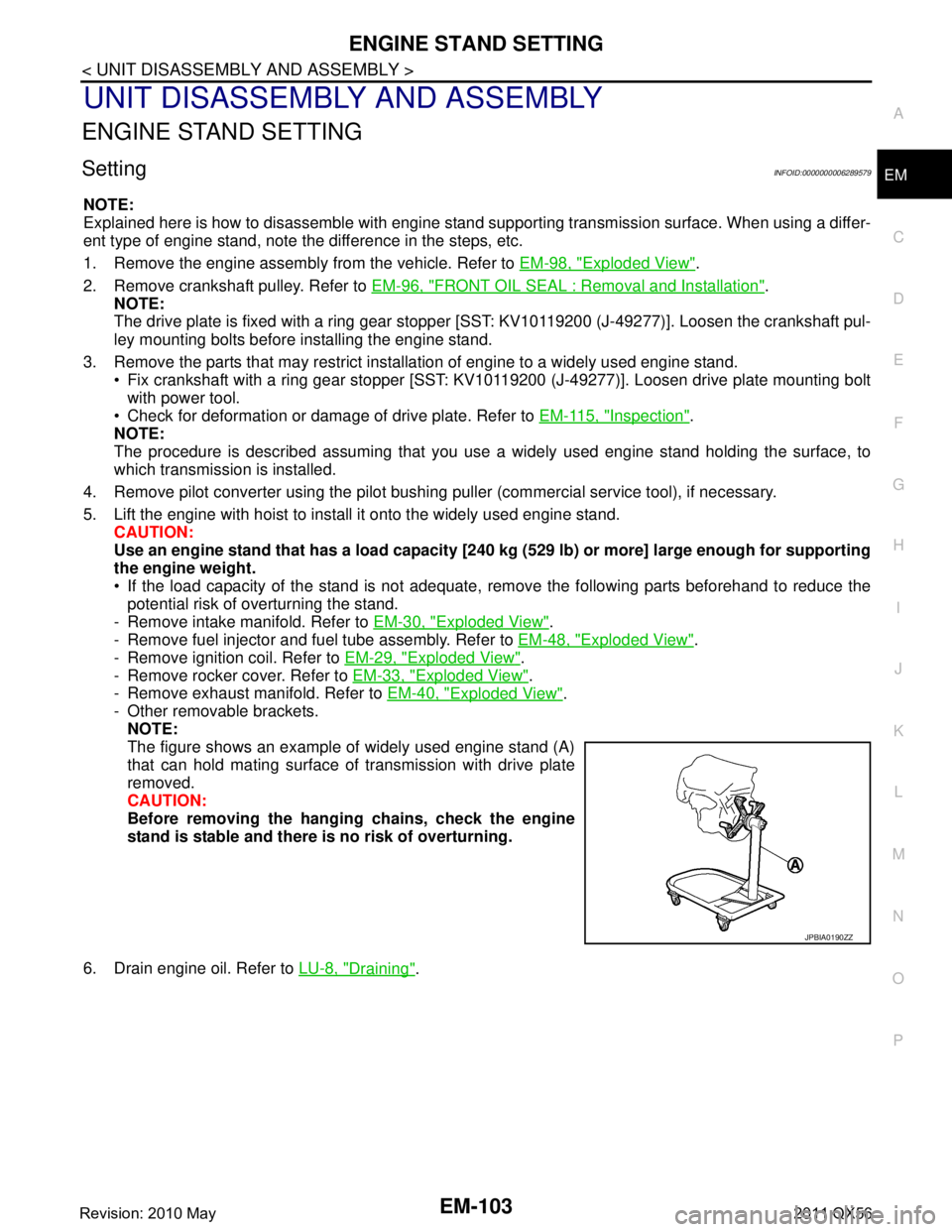
The figure shows an example of widely used engine stand (A)
that can hold mating surface of transmission with drive plate
removed.
CAUTION:
Before removing the hang ing chains, check the engine
stand is stable and there is no risk of overturning.
6. Drain engine oil. Refer to LU-8, "
Draining".
JPBIA0190ZZ
Revision: 2010 May2011 QX56
Page 3067 of 5598

PREPARATIONHA-11
< PREPARATION >
C
DE
F
G H
J
K L
M A
B
HA
N
O P
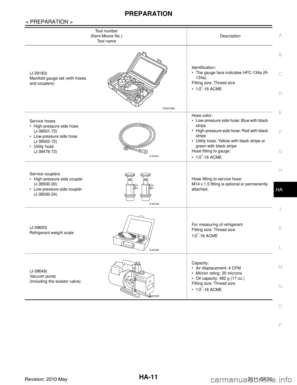
(J-39183)
Manifold gauge set (with hoses
and couplers) Identification:
The gauge face indicates HFC-134a (R-
134a).
Fitting size: Thread size
1/2
″-16 ACME
Service hoses
High-pressure side hose (J-39501-72)
Low-pressure side hose
(J-39502-72)
Utility hose (J-39476-72) Hose color:
Low-pressure side hose: Blue with black
stripe
High-pressure side hose: Red with black stripe
Utility hose: Yellow with black stripe or
green with black stripe
Hose fitting to gauge:
1/2
″-16 ACME
Service couplers
High-pressure side coupler (J-39500-20)
Low-pressure side coupler (J-39500-24) Hose fitting to service hose:
M14 x 1.5 fitting is optional or permanently
attached.
(J-39650)
Refrigerant weight scale For measuring of refrigerant
Fitting size: Thread size
1/2
″-16 ACME
(J-39649)
Va c u u m p u m p
(Including the isolator valve) Capacity:
Air displacement: 4 CFM
Micron rating: 20 microns
Oil capacity: 482 g (17 oz.)
Fitting size: Thread size
1/2
″-16 ACME
Tool number
(Kent-Moore No.)
Tool name Description
RJIA0196E
S-NT201
S-NT202
S-NT200
S-NT203
Revision: 2010 May2011 QX56
Page 3068 of 5598

HA-12
< PREPARATION >
PREPARATION
Commercial Service Tool
INFOID:0000000006276518
Sealant or/and LubricantINFOID:0000000006276143
HFC-134a (R-134a) Service Tool and Equipment
Never mix HFC-134a (R-134a) refrigerant and/or its s pecified lubricant with CFC-12 (R-12) refrigerant and/
or its lubricant.
Separate and non-interchangeable service equipment must be used for handling each type of refrigerant/ lubricant.
Refrigerant container fittings, service hose fittings and service equipment fittings (equipment which handles
refrigerant and/or lubricant) are different between CF C-12 (R-12) and HFC-134a (R-134a). This is to avoid
mixed use of the refrigerants/lubricant.
Never use adapters that convert one size fitting to another: refrigerant/lubricant contamination occurs and
compressor malfunction may result.
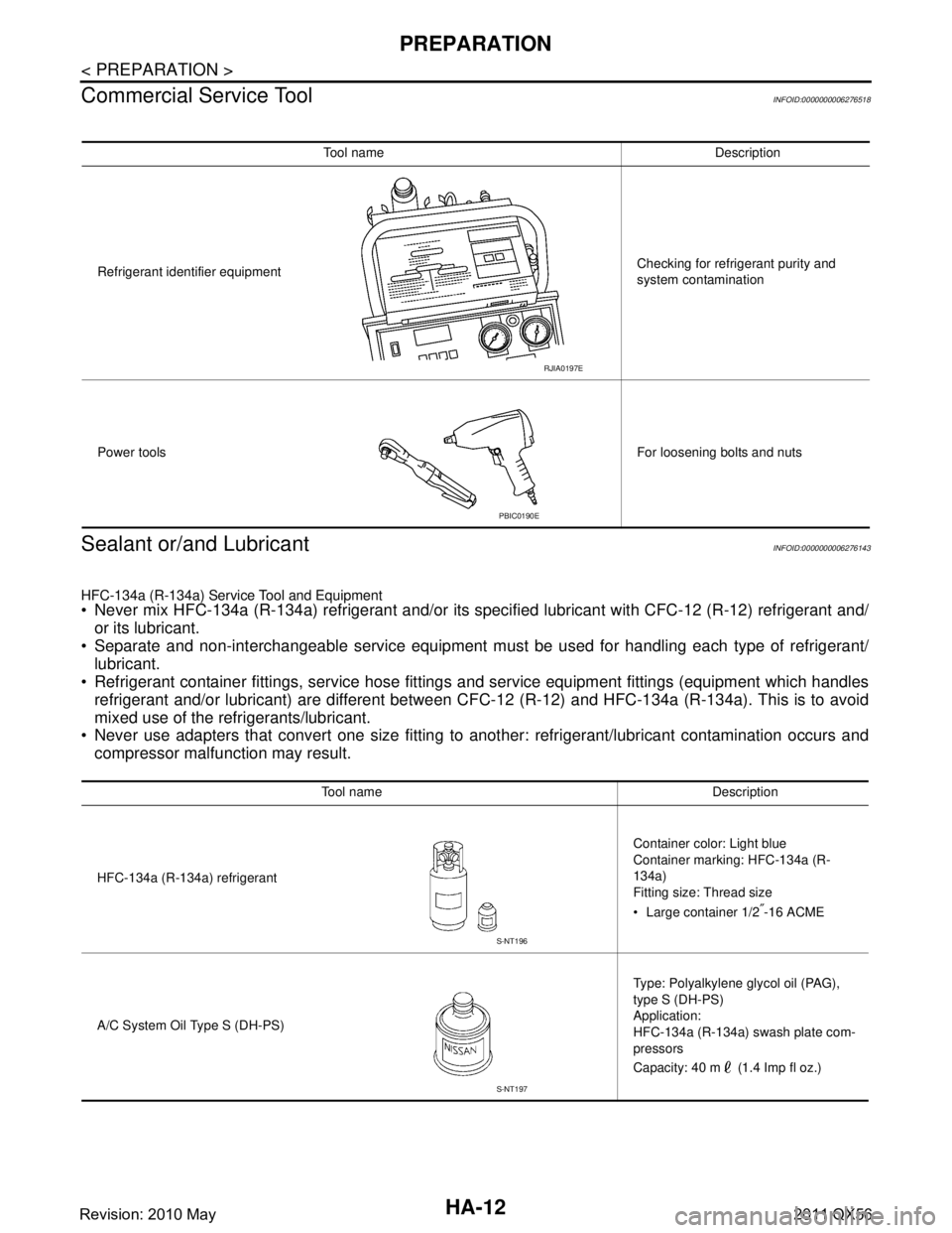
Tool name Description
Refrigerant identifier equipment Checking for refrigerant purity and
system contamination
Power tools For loosening bolts and nuts
RJIA0197E
PBIC0190E
Tool name Description
HFC-134a (R-134a) refrigerant Container color: Light blue
Container marking: HFC-134a (R-
134a)
Fitting size: Thread size
Large container 1/2
″-16 ACME
A/C System Oil Type S (DH-PS) Type: Polyalkylene glycol oil (PAG),
type S (DH-PS)
Application:
HFC-134a (R-134a) swash plate com-
pressors
Capacity: 40 m (1.4 Imp fl oz.)
S-NT196
S-NT197
Revision: 2010 May2011 QX56
Page 3106 of 5598

HA-50
< SERVICE DATA AND SPECIFICATIONS (SDS)
SERVICE DATA AND SPECIFICATIONS (SDS)
SERVICE DATA AND SPECIFICATIONS (SDS)
SERVICE DATA AND SPECIFICATIONS (SDS)
CompressorINFOID:0000000006276197
LubricantINFOID:0000000006276198
RefrigerantINFOID:0000000006276199
Engine Idling SpeedINFOID:0000000006276200
Refer to EC-538, "Idle Speed".
Belt TensionINFOID:0000000006276201
Refer to EM-20, "TensionAdjustment".
Model VALEO THERMAL SYSTEMS JAPAN make
DSK-17D
Ty p e Fixation displacement swash plate
Displacement
cm
3 (cu in)/rev Maximum 175 (10.7)
Direction of rotation Clockwise (viewed from clutch)
Drive belt Poly V
Disc to pulley clearance
mm (in) Standard 0.3 – 0.6 (0.012 – 0.024)
Name
UV Luminaus Oil Type S (DH-PS)
Capacity
m (Imp fl oz) Total in system 210 (7.1)
Compressor (service part) charging
amount
210 (7.1)
Ty p e
HFC-134a (R-134a)
Capacity
kg (lb) 1.05 (2.32)
Revision: 2010 May2011 QX56
Page 3119 of 5598
![INFINITI QX56 2011 Factory Service Manual
COMPONENT PARTSHAC-13
< SYSTEM DESCRIPTION > [AUTOMATIC AIR CONDITIONING]
C
D
E
F
G H
J
K L
M A
B
HAC
N
O P
Rear Blower MotorINFOID:0000000006275858
The rear blower motor utilizes a brush-less motor INFINITI QX56 2011 Factory Service Manual
COMPONENT PARTSHAC-13
< SYSTEM DESCRIPTION > [AUTOMATIC AIR CONDITIONING]
C
D
E
F
G H
J
K L
M A
B
HAC
N
O P
Rear Blower MotorINFOID:0000000006275858
The rear blower motor utilizes a brush-less motor](/img/42/57033/w960_57033-3118.png)
COMPONENT PARTSHAC-13
< SYSTEM DESCRIPTION > [AUTOMATIC AIR CONDITIONING]
C
D
E
F
G H
J
K L
M A
B
HAC
N
O P
Rear Blower MotorINFOID:0000000006275858
The rear blower motor utilizes a brush-less motor with a rotating
magnet. Quietness is improved comp aring to a conventional motor
(brush motor) that rotates coil while brush functions as contact
points.
Refrigerant Pressure SensorINFOID:0000000006275859
Description
Refrigerant pressure sensor is installed to upper porti on of liquid tank. The refrigerant pressure sensor con-
verts high-pressure side refrigerant pressure into vo ltage and outputs it to ECM. ECM operates cooling system
protection and idle speed control according to voltage value that is input.
Structure and operation
The refrigerant pressure sensor is a capacitance type sensor. It consists of a pressure detection area and a
signal processing area. The pressure detection area, wh ich is a variable capacity condenser, changes internal
static capacitance according to pressure force. The signal processing area detects the static capacitance of
the pressure detection area, converts the static capacitance into a voltage value, and transmits the voltage
value to ECM.
RJIA2467J
ZHA152H
PBIB2657E
Revision: 2010 May2011 QX56