coolant level INFINITI QX56 2011 Factory Service Manual
[x] Cancel search | Manufacturer: INFINITI, Model Year: 2011, Model line: QX56, Model: INFINITI QX56 2011Pages: 5598, PDF Size: 94.53 MB
Page 5 of 5598

QUICK REFERENCE CHART QX56
BRAKE PEDAL
Unit : mm (in)
FRONT DISK BRAKE
Unit : mm (in)
REAR DISK BRAKE
Unit : mm (in)
REFILL CAPACITIESELS00040
Item Standard
Brake pedal height 168.5 (6.63) – 178.5 (7.03)
Depressed brake pedal height
[Depressing 490 N (50 kg, 110 lb) while turning the engine ON] 100 (3.94) or more
Item Limit
Brake pad Wear thickness 1.5 (0.059)
Disc rotor Wear thickness 28.5 (1.122)
Thickness variation (measured at 8 positions) 0.015 (0.0006)
Runout (with it attached to the vehicle) 0.053 (0.0021)
Item Limit
Brake pad Wear thickness 2.0 (0.079)
Disc rotor Wear thickness 18.0 (0.709)
Thickness variation (measured at 8 positions) 0.015 (0.0006)
Runout (with it attached to the vehicle) 0.05 (0.0020)
UNIT
Liter US measure
Fuel tank 98.4 26 gal
Engine Coolant ( With reservoir tank ) at MAX level 14.9 15-6/8 qt
Engine oil Drain and refill
With oil filter change 6.5 6-7/8 qt
Without oil filter change 6.2 6-4/8 qt
Dry engine (Overhaul) 7.6 8 qt
Transmission 10.0 10-5/8 qt
Transfer 1.5 3-1/8 pt
Final drive Front 0.75 1-5/8 pt
Rear 1.75 3-3/4 pt
Power steering system 1.0 7/8 qt
Air conditioning system Compressor oil 0.21 7.1 fl oz
Refrigerant 1.05 kg 2.32 lb
2011
Page 807 of 5598
![INFINITI QX56 2011 Factory Service Manual
CCS-72
< BASIC INSPECTION >[ICC]
LASER BEAM AIMING ADJUSTMENT
LASER BEAM AIMING ADJUSTMENT
DescriptionINFOID:0000000006224293
OUTLINE OF LASER BEAM AIMING ADJUSTMENT
Always adjust the laser beam aimi INFINITI QX56 2011 Factory Service Manual
CCS-72
< BASIC INSPECTION >[ICC]
LASER BEAM AIMING ADJUSTMENT
LASER BEAM AIMING ADJUSTMENT
DescriptionINFOID:0000000006224293
OUTLINE OF LASER BEAM AIMING ADJUSTMENT
Always adjust the laser beam aimi](/img/42/57033/w960_57033-806.png)
CCS-72
< BASIC INSPECTION >[ICC]
LASER BEAM AIMING ADJUSTMENT
LASER BEAM AIMING ADJUSTMENT
DescriptionINFOID:0000000006224293
OUTLINE OF LASER BEAM AIMING ADJUSTMENT
Always adjust the laser beam aiming after removing and installing or replacing the ICC sensor.
CAUTION:
The system does not operate normally
unless the laser beam aiming adjustment is performed. Always
perform it.
1. Set the ICC target board [SST: KV99110100 (J-45718)] to the correct position in front of the vehicle.
2. Set the laser beam aiming mode (“LASER BEAM AD JUST” on “Work support”) with CONSULT-III, and
then perform the adjustment according to the displa y. (Manually turn the up-down direction adjusting
screw for vertical adjustment. ICC sensor adjusts the automatic aiming for the horizontal direction.)
CAUTIONARY POINT FOR LASER BEAM AIMING ADJUSTMENT
CAUTION:
For laser beam aiming adjustment, choose a level location where a view can be obtained without any
obstruction as far as 12 m (39 ft) or more in the forward direction.
Adjust laser beam aiming for 5 second s or more after starting engine.
Adjust the laser beam aiming with CONSULT-III. (The laser beam aiming cannot be adjusted without
CONSULT-III.)
Never enter the vehicle during laser beam aiming adjustment.
Never look directly into the laser beam sour ce (ICC sensor body window) during laser beam aiming
adjustment.
Laser beam aiming adjustment is performed at idle. At this time, turn the headlamps OFF.
Work Procedure (Preparation)INFOID:0000000006224294
1.ADVANCE PREPARATION FOR LASER BEAM AIMING ADJUSTMENT
1. Adjust all tire pressure to the specified value.
2. Empty the vehicle. (Remove any luggage from the passenger compartment, luggage room, etc.)
3. Shift the selector lever to “P” pos ition, and release the parking brake.
4. Fully fill the fuel tank, and then check that t he coolant and oils are filled up to correct level.
5. Clean off the ICC sensor body window with a soft cloth.
>> Go to CCS-72, "
Work Procedure (Setting The ICC Tar-
get Board)".
Work Procedure (Setting The ICC Target Board)INFOID:0000000006224295
DESCRIPTION
Accurate adjustment of the laser beam requires t hat the ICC target board be accurately positioned.
CAUTION:
If the laser beam is adjusted with the ICC target board in the incorrect position, the ICC system does
not function normally.
1.ICC TARGET BOARD HEIGHT ADJUSTMENT
1 : ICC sensor
JSOIA0372ZZ
Revision: 2010 May2011 QX56
Page 950 of 5598
CO-8
< PERIODIC MAINTENANCE >
ENGINE COOLANT
PERIODIC MAINTENANCE
ENGINE COOLANT
InspectionINFOID:0000000006289657
LEVEL
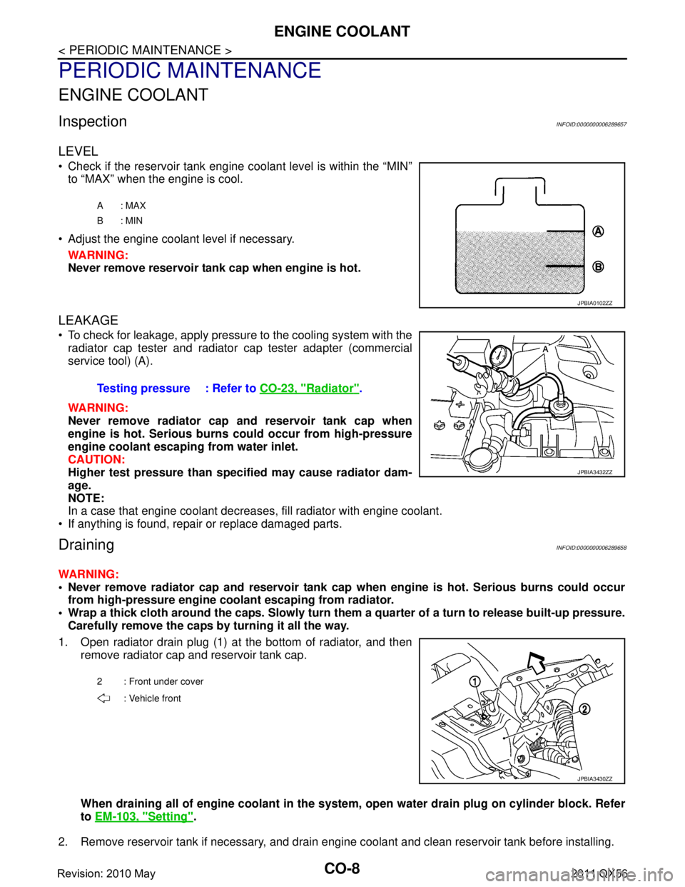
Check if the reservoir tank engine coolant level is within the “MIN”to “MAX” when the engine is cool.
Adjust the engine coolant level if necessary. WARNING:
Never remove reservoir tank cap when engine is hot.
LEAKAGE
To check for leakage, apply pressure to the cooling system with theradiator cap tester and radiator cap tester adapter (commercial
service tool) (A).
WARNING:
Never remove radiator cap and reservoir tank cap when
engine is hot. Serious burns could occur from high-pressure
engine coolant escaping from water inlet.
CAUTION:
Higher test pressure than specified may cause radiator dam-
age.
NOTE:
In a case that engine coolant decreas es, fill radiator with engine coolant.
If anything is found, repair or replace damaged parts.
DrainingINFOID:0000000006289658
WARNING:
Never remove radiator cap and reservoir tank cap when engine is hot. Serious burns could occur
from high-pressure engine co olant escaping from radiator.
Wrap a thick cloth around the caps. Slowly turn them a quarter of a turn to release built-up pressure.
Carefully remove the caps by turning it all the way.
1. Open radiator drain plug (1) at the bottom of radiator, and then remove radiator cap and reservoir tank cap.
When draining all of engine cool ant in the system, open water drai n plug on cylinder block. Refer
to EM-103, "
Setting".
2. Remove reservoir tank if necessary, and drain engine coolant and clean reservoir tank before installing.
A: MAX
B: MIN
JPBIA0102ZZ
Testing pressure : Refer to CO-23, "Radiator".
JPBIA3432ZZ
2 : Front under cover
: Vehicle front
JPBIA3430ZZ
Revision: 2010 May2011 QX56
Page 951 of 5598
ENGINE COOLANTCO-9
< PERIODIC MAINTENANCE >
C
DE
F
G H
I
J
K L
M A
CO
NP
O
3. Check drained engine coolant for contaminants such as rust, corrosion or discoloration.
If contaminated, flush the engine cooling system. Refer to CO-10, "
Flushing".
RefillingINFOID:0000000006289659
1. Install reservoir tank if removed, and radiator drain plug.
CAUTION:
Be sure to clean drain plug and install with new O-ring. Refer to CO-13, "
Exploded View".
If water drain plug on cylinder block is removed, close and tighten it. Refer to EM-107, "
Disassem-
bly and Assembly".
2. Check that each hose clamp is firmly tightened.
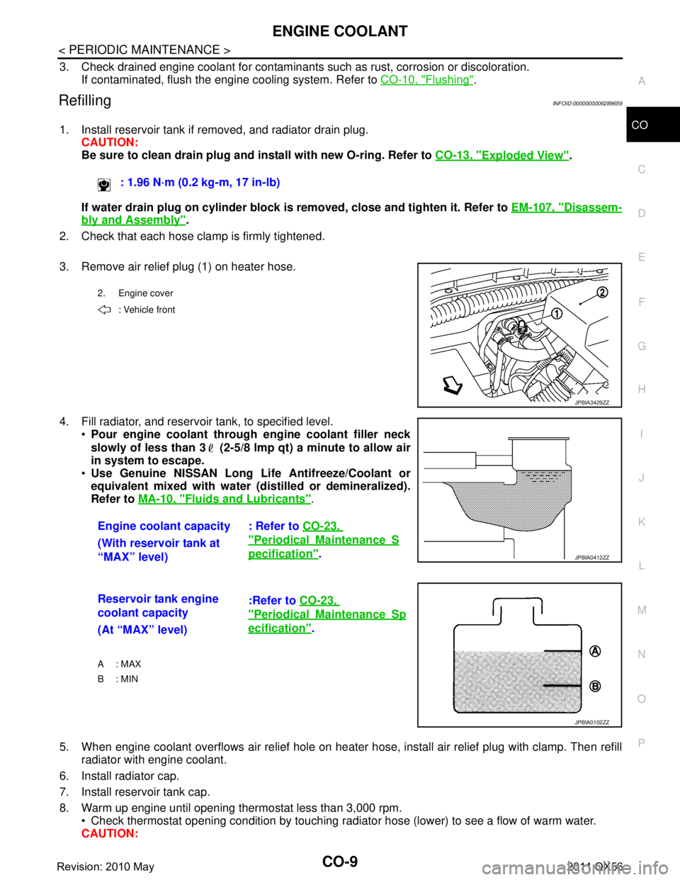
3. Remove air relief plug (1) on heater hose.
4. Fill radiator, and reservoir tank, to specified level. Pour engine coolant through engine coolant filler neck
slowly of less than 3 (2-5/8 lmp qt) a minute to allow air
in system to escape.
Use Genuine NISSAN Long Li fe Antifreeze/Coolant or
equivalent mixed with water (dis tilled or demineralized).
Refer to MA-10, "
Fluids and Lubricants".
5. When engine coolant overflows air relief hole on heater hos e, install air relief plug with clamp. Then refill
radiator with engine coolant.
6. Install radiator cap.
7. Install reservoir tank cap.
8. Warm up engine until opening thermostat less than 3,000 rpm. Check thermostat opening condition by touching radiat or hose (lower) to see a flow of warm water.
CAUTION: : 1.96 N·m (0.2 kg-m, 17 in-lb)
2. Engine cover
: Vehicle front
JPBIA3429ZZ
Engine coolant capacity : Refer to CO-23,
"PeriodicalMaintenanceS
pecification".
(With reservoir tank at
“MAX” level)JPBIA0412ZZ
Reservoir tank engine
coolant capacity :Refer to
CO-23,
"PeriodicalMaintenanceSp
ecification".
(At “MAX” level)
A : MAX
B: MIN
JPBIA0102ZZ
Revision: 2010 May2011 QX56
Page 952 of 5598
CO-10
< PERIODIC MAINTENANCE >
ENGINE COOLANT
Watch water temperature gauge so as not to overheat engine.
9. Stop the engine and cool down to less than approximately 50 °C (122 °F).
Cool down using fan to reduce the time.
If necessary, refill radiator up to filler neck with engine coolant.
10. Refill reservoir tank to “MAX” level line with engine coolant if necessary.
11. Repeat steps 6 through 10 two or more times with reservoir tank cap installed until engine coolant level no longer drops.
12. Check cooling system for leakage with engine running.
13. Warm up the engine, and check for sound of engine coolant flow while running engine from idle up to 3,000 rpm with heater temperature controller set at several position between “COOL” and “WARM”.
Sound may be noticeable at heater unit.
14. Repeat step 13 three times.
15. If sound is heard, bleed air from cooling system by repeating step 4, and steps from 6 to 14 until engine
coolant level no longer drops.
FlushingINFOID:0000000006289660
1. Install reservoir tank if removed, and radiator drain plug. CAUTION:
Be sure to clean drain plug and install with new O-ring. Refer to CO-13, "
Exploded View".
If water drain plug on cylinder block is removed, close and tighten it. Refer to EM-107, "
Disassem-
bly and Assembly".
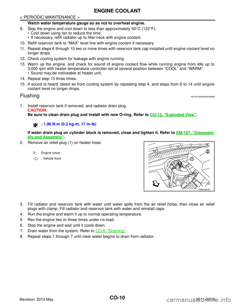
2. Remove air relief plug (1) on heater hose.
3. Fill radiator and reservoir tank with water until water spills from the air relief holes, then close air relief
plugs with clamp. Fill radiator and reservoir tank with water and reinstall caps.
4. Run the engine and warm it up to normal operating temperature.
5. Rev the engine two or three times under no-load.
6. Stop the engine and wait until it cools down.
7. Drain water from the system. Refer to CO-8, "
Draining".
8. Repeat steps 1 through 7 until clear water begins to drain from radiator. : 1.96 N·m (0.2 kg-m, 17 in-lb)
2. Engine cover
: Vehicle front
JPBIA3429ZZ
Revision: 2010 May2011 QX56
Page 965 of 5598
SERVICE DATA AND SPECIFICATIONS (SDS)
CO-23
< SERVICE DATA AND SPECIFICATIONS (SDS)
C
D E
F
G H
I
J
K L
M A
CO
NP
O
SERVICE DATA AND SPECIFICATIONS (SDS)
SERVICE DATA AND SPECIFICATIONS (SDS)
Periodical Maintenance SpecificationINFOID:0000000006289675
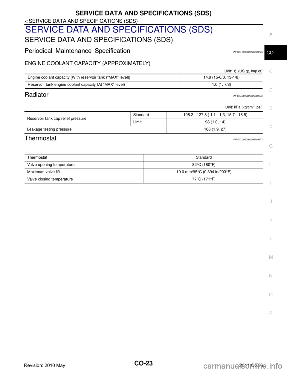
ENGINE COOLANT CAPACITY (APPROXIMATELY)
Unit: (US qt, Imp qt)
RadiatorINFOID:0000000006289676
Unit: kPa (kg/cm2, psi)
ThermostatINFOID:0000000006289677
Engine coolant capacity [With reservoir tank (“MAX” level)] 14.9 (15-6/8, 13-1/8)
Reservoir tank engine coolant capacity (At “MAX” level) 1.0 (1, 7/8)
Reservoir tank cap relief pressure
Standard 108.2 - 127.8 ( 1.1 - 1.3, 15.7 - 18.5)
Limit 98 (1.0, 14)
Leakage testing pressure 186 (1.9, 27)
ThermostatStandard
Valve opening temperature 82 °C (180 °F)
Maximum valve lift 10.0 mm/95 °C (0.394 in/203 °F)
Valve closing temperature 77 °C (171 °F)
Revision: 2010 May2011 QX56
Page 1305 of 5598
![INFINITI QX56 2011 Factory Service Manual
DAS-340
< BASIC INSPECTION >[LDW & LDP]
CAMERA AIMING ADJUSTMENT
CAMERA AIMING ADJUSTMENT
DescriptionINFOID:0000000006223734
Always adjust the camera aiming after removing
and installing or replacin INFINITI QX56 2011 Factory Service Manual
DAS-340
< BASIC INSPECTION >[LDW & LDP]
CAMERA AIMING ADJUSTMENT
CAMERA AIMING ADJUSTMENT
DescriptionINFOID:0000000006223734
Always adjust the camera aiming after removing
and installing or replacin](/img/42/57033/w960_57033-1304.png)
DAS-340
< BASIC INSPECTION >[LDW & LDP]
CAMERA AIMING ADJUSTMENT
CAMERA AIMING ADJUSTMENT
DescriptionINFOID:0000000006223734
Always adjust the camera aiming after removing
and installing or replacing the lane camera unit.
CAUTION:
Place the vehicle on level ground when th e camera aiming adjustment is operated.
Follow the CONSULT-III when performing the came ra aiming. (Camera aiming adjustment cannot be
operated without CONSULT-III.)
Work Procedure (Preparation)INFOID:0000000006223735
1.PERFORM SELF-DIAGNOSIS
Perform self-diagnosis of ADAS control unit and lane camera unit.
Is any DTC detected?
Except “C1B01”>>Perform diagnosis on the detected DTC and repair or replace the applicable item. Refer to
DAS-310, "
DTC Index" (ICC/ADAS) or DAS-316, "DTC Index" (LANE CAMERA).
“C1B01” or no DTC>>GO TO 2.
2.PREPARATION BEFORE CAMERA AIMING ADJUSTMENT
1. Perform pre-inspection for diagnosis. Refer to DAS-335, "
Inspection Procedure".
2. Adjust the tire pressure to the specified pressure value.
3. Maintain no-load in vehicle.
4. Check if coolant and engine oil are filled up to correct level and fuel tank is full.
5. Shift the selector lever to “P” position and release the parking brake.
6. Clean the windshield.
7. Completely clear off the instrument panel.
>> GO TO 3.
3. PREPARATION OF AIMING ADJUSTMENT JIG
Prepare the aiming adjustment jig according to the following procedure and the figure.
1. Print out the target mark attached in this service manual. Refer to DAS-343, "
Work Procedure (Target
Mark Sample)".
2. Stick a printed target mark on the board with a scotch tape or a piece of double-sided tape.
NOTE:
Use the board that peripheral area of the ta rget is monochrome such as a white-board.
Notice that the cross of the target is horizontal and vertical.
JPOIA0011ZZ
Revision: 2010 May2011 QX56
Page 1789 of 5598
CAB MOUNTING INSULATORDLK-253
< REMOVAL AND INSTALLATION >
C
DE
F
G H
I
J
L
M A
B
DLK
N
O P
Remove brake tube from connector (front wheel well LH and RH side). Refer to BR-22, "FRONT :
Exploded View"
Vehicle center side
Remove A/T control cable from manual lever. Refer to TM-178, "
Removal and Installation".
Separate parking brake rear cable (LH and RH) from parking brake front cable. Refer to PB-5, "
Removal
and Installation".
Remove engine room harness connector (frame assembly RH center side). Refer to PG-146, "
Engine
Room Harness"
- Remove harness connector protector.
- Disconnect chassis harness connector from engine room harness connector.
- Remove harness bracket bolt, and then remove engi ne room harness connector from frame assembly.
Vehicle rear side
Remove EVAP hose (canister side).
Remove rear final drive breather hose from air breather tube (body side). Refer to DLN-201, "
Removal
and Installation".
Disconnect body harness connector from chassis harness connectors (frame assembly LH rear side).
Refer to PG-150, "
Body Harness"
6. Set safety stand to frame assembly. Release arm of 2-pole lift.
7. Remove cab mounting insulator bolts.
8. Set arm of 2-pole lift to body side sill portion of body.
9. Slowly lift 2-pole lift.
CAUTION:
Check that there is no inte rference with the vehicle.
Check that all connection points are disconnected.
10. Remove cab mounting insulator.
INSTALLATION
Note the following items, and then install in the reverse order of removal.
CAUTION:
Before starting engine, check oil/fl uid levels including engine coolant and engine oil. If levels are
less than the required quantity, fill to the specified level. Refer to MA-10, "
Fluids and Lubricants".
Warm up engine thoroughly to check that there is no leakage of fuel, exhaust gases, or any oil/fluids
including engine oil and engine coolant.
Revision: 2010 May2011 QX56
Page 2025 of 5598

EC-1
ENGINE
C
DE
F
G H
I
J
K L
M
SECTION EC
A
EC
N
O P
CONTENTS
ENGINE CONTROL SYSTEM
VK56VD
PRECAUTION ................ ...............................
9
PRECAUTIONS .............................................. .....9
Precaution for Supplemental Restraint System
(SRS) "AIR BAG" and "SEAT BELT PRE-TEN-
SIONER" ............................................................. ......
9
Precaution for Procedure without Cowl Top Cover ......9
Precautions For Xenon Headlamp Service ...............9
On Board Diagnostic (OBD) System of Engine
and A/T ....................................................................
10
General Precautions ...............................................10
PREPARATION ...........................................14
PREPARATION .............................................. ....14
Special Service Tools .......................................... ....14
Commercial Service Tools ......................................14
SYSTEM DESCRIPTION .............................16
COMPONENT PARTS ................................... ....16
Component Parts Location .................................. ....16
Component Description ...........................................19
Accelerator Pedal Position Sensor ..........................21
Air Fuel Ratio (A/F) Sensor 1 ..................................21
ASCD Brake Switch & Stop Lamp Switch ...............21
ASCD Steering Switch ............................................21
ASCD Indicators ......................................................21
Battery Current Sensor (With Battery Tempera-
ture Sensor) ............................................................
22
Camshaft Position Sensor .......................................22
Crankshaft Position Sensor .....................................23
ECM ........................................................................23
Electric Throttle Control Actuator ............................23
Electrically-controlled cooling fan coupling .............24
Engine Coolant Temperature Sensor ......................25
Engine Oil Temperature Sensor ..............................25
EVAP Control System Pressure Sensor .................26
EVAP Canister Vent Control Valve .........................26
EVAP Canister Purge Volume Control Solenoid
Valve .................................................................... ....
26
Fuel Injector .............................................................26
Fuel Level Sensor ....................................................26
Fuel Pump Control Module ......................................27
Fuel Rail Pressure Sensor .......................................27
Fuel Tank Temperature Sensor ...............................27
Heated Oxygen Sensor 2 ........................................27
High Pressure Fuel Pump .......................................28
ICC Brake Switch & Stop Lamp Switch ...................29
ICC Steering Switch ................................................29
Ignition Coil With Power Transistor .........................29
Intake Valve Timing Control Solenoid Valve ...........29
Knock Sensor ...................................................... ....30
Low Fuel Pressure Sensor ......................................30
Low Pressure Fuel Pump ........................................30
Malfunction Indicator Lamp (MIL) ............................30
Manifold Absolute Pressure Sensor ........................31
Mass Air Flow Sensor (With Intake Air Tempera-
ture Sensor) .............................................................
31
Power Steering Pressure (PSP) Sensor ..................31
Refrigerant Pressure Sensor ............................... ....32
VVEL Actuator Motor ...............................................32
VVEL Actuator Motor Relay .....................................32
VVEL Control Module ..............................................32
VVEL Control Shaft Position Sensor .......................32
STRUCTURE AND OPERATION .....................33
Positive Crankcase Ventilation ................................33
On Board Refueling Vapor Recovery (ORVR) ........34
SYSTEM ............................................................35
ENGINE CONTROL SYSTEM ........................ ...........35
ENGINE CONTROL SYSTEM : System Diagram ....35
ENGINE CONTROL SYSTEM : System Descrip-
tion ...........................................................................
35
DIRECT INJECTION GASOLINE SYSTEM .......... ....36
DIRECT INJECTION GASOLINE SYSTEM :
System Diagram .....................................................
36
Revision: 2010 May2011 QX56
Page 2043 of 5598
![INFINITI QX56 2011 Factory Service Manual
COMPONENT PARTSEC-19
< SYSTEM DESCRIPTION > [VK56VD]
C
D
E
F
G H
I
J
K L
M A
EC
NP
O
Component DescriptionINFOID:0000000006217657
1. ASCD steering switch
ICC steering switch 2. Snow mode switch 3. Fu INFINITI QX56 2011 Factory Service Manual
COMPONENT PARTSEC-19
< SYSTEM DESCRIPTION > [VK56VD]
C
D
E
F
G H
I
J
K L
M A
EC
NP
O
Component DescriptionINFOID:0000000006217657
1. ASCD steering switch
ICC steering switch 2. Snow mode switch 3. Fu](/img/42/57033/w960_57033-2042.png)
COMPONENT PARTSEC-19
< SYSTEM DESCRIPTION > [VK56VD]
C
D
E
F
G H
I
J
K L
M A
EC
NP
O
Component DescriptionINFOID:0000000006217657
1. ASCD steering switch
ICC steering switch 2. Snow mode switch 3. Fuel level sensor unit and fuel pump
assembly (with fuel tank temperature
sensor)
4. Fuel pump control module (FPCM) 5. EVAP canister vent control valve 6. EVAP canister
7. EVAP control system pressure sen- sor 8. Stop lamp switch 9. ASCD brake switch
ICC brake switch
10. Accelerator pedal position sensor
JSBIA0606ZZ
Component Reference
ECM EC-23, "
ECM"
Malfunction indicator lamp (MIL)EC-30, "Malfunction Indicator Lamp (MIL)"
Ignition coil with power transistorEC-29, "Ignition Coil With Power Transistor"
Accelerator pedal position sensorEC-21, "Accelerator Pedal Position Sensor"
Mass air flow sensor
EC-31, "Mass Air Flow Sensor (With Intake Air Temperature Sen-
sor)"Intake air temperature sensor
Electric throttle control actuator
EC-23, "
Electric Throttle Control Actuator"Throttle control motor relay
Throttle control motor
Throttle position sensor
Crankshaft position sensorEC-23, "
Crankshaft Position Sensor"
Camshaft position sensorEC-22, "Camshaft Position Sensor"
Engine coolant temperature sensorEC-25, "Engine Coolant Temperature Sensor"
Revision: 2010 May2011 QX56