steering INFINITI QX60 2023 Service Manual
[x] Cancel search | Manufacturer: INFINITI, Model Year: 2023, Model line: QX60, Model: INFINITI QX60 2023Pages: 636, PDF Size: 7.28 MB
Page 257 of 636
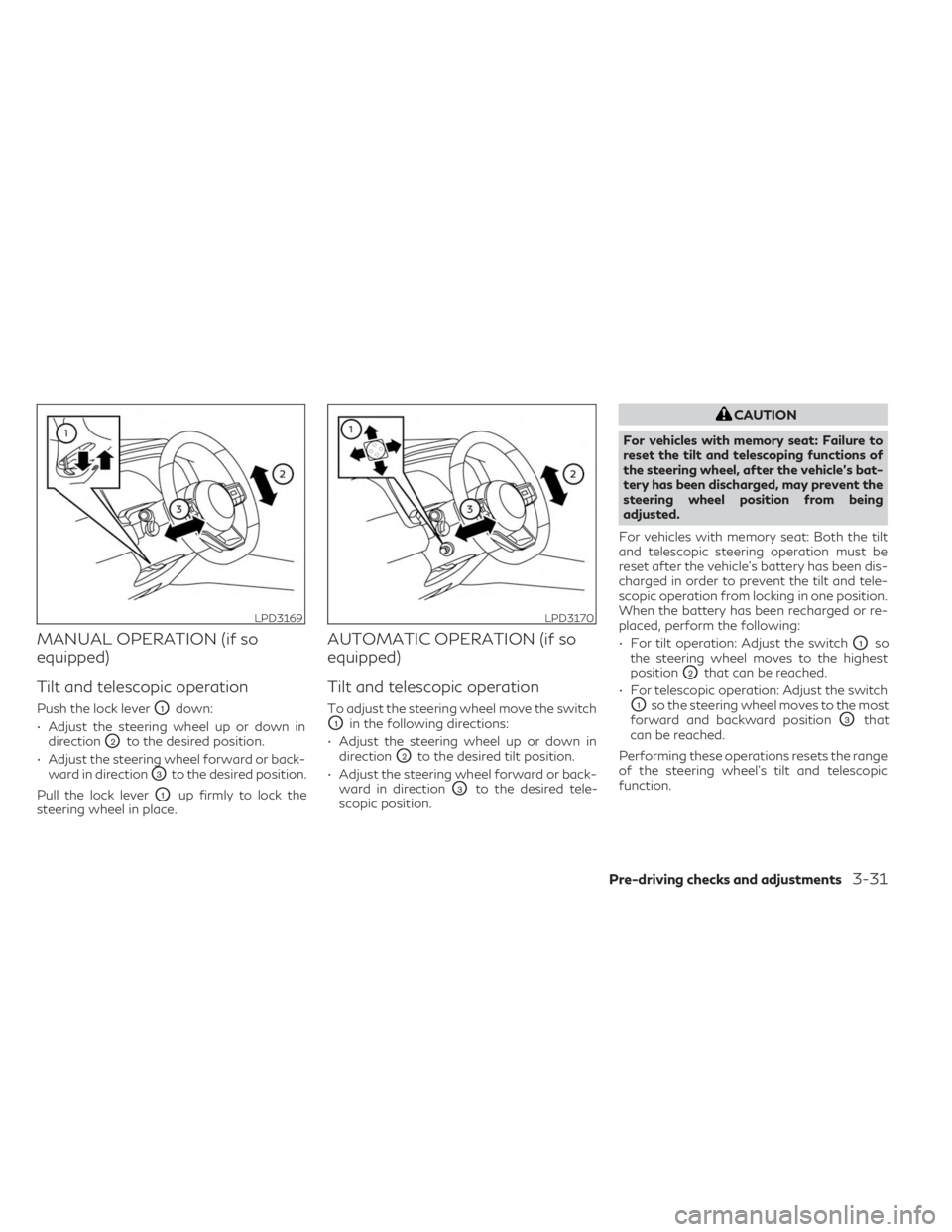
MANUAL OPERATION (if so
equipped)
Tilt and telescopic operation
Push the lock leverO1down:
• Adjust the steering wheel up or down in direction
O2to the desired position.
• Adjust the steering wheel forward or back- ward in direction
O3to the desired position.
Pull the lock lever
O1up firmly to lock the
steering wheel in place.
AUTOMATIC OPERATION (if so
equipped)
Tilt and telescopic operation
To adjust the steering wheel move the switch
O1in the following directions:
• Adjust the steering wheel up or down in direction
O2to the desired tilt position.
• Adjust the steering wheel forward or back- ward in direction
O3to the desired tele-
scopic position.
CAUTION
For vehicles with memory seat: Failure to
reset the tilt and telescoping functions of
the steering wheel, after the vehicle’s bat-
tery has been discharged, may prevent the
steering wheel position from being
adjusted.
For vehicles with memory seat: Both the tilt
and telescopic steering operation must be
reset after the vehicle’s battery has been dis-
charged in order to prevent the tilt and tele-
scopic operation from locking in one position.
When the battery has been recharged or re-
placed, perform the following:
• For tilt operation: Adjust the switch
O1so
the steering wheel moves to the highest
position
O2that can be reached.
• For telescopic operation: Adjust the switch
O1so the steering wheel moves to the most
forward and backward position
O3that
can be reached.
Performing these operations resets the range
of the steering wheel’s tilt and telescopic
function.
LPD3169LPD3170
Pre-driving checks and adjustments3-31
Page 258 of 636
Entry/Exit function (if so equipped)
The memory seat will make the steering
wheel move up automatically when the driv-
er's door is opened and the ignition switch is
in the LOCK position. This lets the driver get
into and out of the seat more easily. The
steering wheel moves back into position
when the driver's door is closed and the igni-
tion switch is pushed.
For additional information, see “Memory
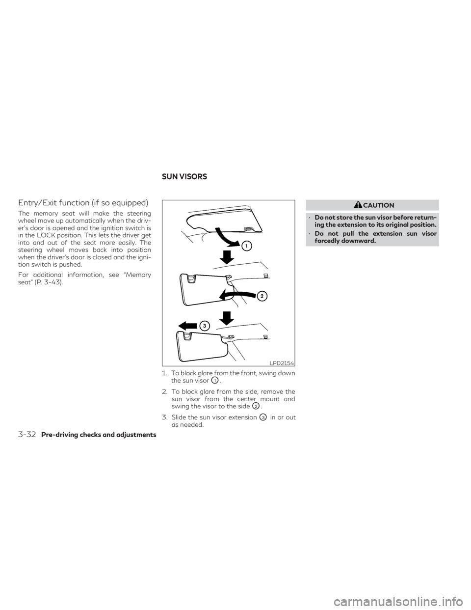
seat” (P. 3-43).1. To block glare from the front, swing downthe sun visor
O1.
2. To block glare from the side, remove the sun visor from the center mount and
swing the visor to the side
O2.
3. Slide the sun visor extension
O3in or out
as needed.
CAUTION
• Do not store the sun visor before return-
ing the extension to its original position.
• Do not pull the extension sun visor
forcedly downward.
LPD2154
SUN VISORS
3-32Pre-driving checks and adjustments
Page 269 of 636
The memory seat system has three features:
• Memory storage function (Key-link) (if soequipped)
• Memory storage function (Switch)
• Entry/exit function
Key-link (if so equipped), when enabled, au-
tomatically retains the driver’s or passenger’s
(if so equipped) last seat, automatic steering
wheel, and outside mirror positions for that
specific key when the ignition is positioned
from ON to OFF.
Each memory switch button (1 or 2) on the
driver’s door or passenger’s door (if so
equipped) can also store one additional posi-
tion which is independent of the key-linked
position.
MEMORY STORAGE FUNCTION
Two positions for the driver's seat, steering
wheel, and outside mirrors or passenger’s
seat (if so equipped) can be stored in the
memory seat system.
NOTE:
• The vehicle should be stopped while set- ting the memory.
• The driver’s and passenger’s memory stor- age functions are separate from each
other. Follow these procedures to use the memory
system.
1. Place the ignition in the ON or ACC
position.
2. Adjust the driver's seat, steering wheel, and outside mirrors or passenger’s seat (if
so equipped) to the desired positions by
manually operating each adjusting switch.
For additional information, see “Seats”
(P. 1-2), “Steering wheel” (P. 3-30) and
“Outside mirrors” (P. 3-41).
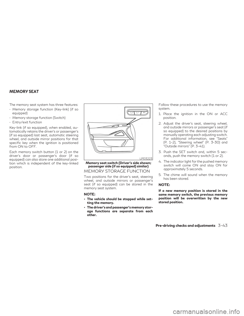
3. Push the SET switch and, within 5 sec- onds, push the memory switch (1 or 2).
4. The indicator light for the pushed memory switch will come ON and stay ON for
approximately 5 seconds.
5. The chime will sound when the memory has been stored.
NOTE:
If a new memory position is stored in the
same memory switch, the previous memory
position will be overwritten by the new
stored position.
LPD3223
Memory seat switch (Driver’s side shown;passenger side (if so equipped) similar)
MEMORY SEAT
Pre-driving checks and adjustments3-43
Page 270 of 636
Confirming memory storage
• Push the SET switch.
• If a memory position has been stored in theswitch (1 or 2) then the indicator light for
the respective switch will stay on for ap-
proximately 5 seconds.
ENTRY/EXIT FUNCTION
This system is designed so that the driver's
seat and automatic operation steering wheel
will automatically move. This allows the
driver to get into and out of the driver’s seat
more easily.
The driver’s seat will slide backward and the
steering wheel will move up:
• When the driver’s door is opened with theignition switch placed in the OFF position.
• When the ignition switch is changed from ACC to OFF with the driver’s door open.
The driver’s seat and steering wheel will re-
turn to the previous position:
• When the ignition switch is changed from ACC or ON while the shift position is in the
P (Park) position. The entry/exit function can be adjusted or
canceled through “Vehicle Settings” in the ve-
hicle information display by performing the
following:
• Switch the Exit Seat Slide from “On” to
“Off”.
• Switch the Exit Steering Up from “On” to “Off”.SETTING MEMORY FUNCTION
The position of the following settings can be
linked to the Intelligent Key and the memo-
rized settings can be available for each Intel-
ligent Key.
To use the memory function, set the climate,
navigation and audio systems to the driver's
preferred settings. Lock the doors with the
Intelligent Key. Each Intelligent Key may be
set with the driver's individual preferences.
When a new Intelligent Key is used, “Connec-
tion with the key has been done” will be dis-
played on the vehicle information display and
the memorized settings are available.
To engage the memorized settings, perform
the following:
1. Carry the Intelligent Key that is linked to the memorized settings. 2. Unlock the doors by wrapping hand
around the capacitive door handle or the
button on the Intelligent Key.
3. Place the ignition switch in the ON posi- tion. The settings linked to the Intelligent
Key will start. .
For additional information, see “INFINITI In-
Touch™ Owner’s Manual” (P. 4-2) and
“Heater and air conditioner (automatic)”
(P. 4-29).
SYSTEM OPERATION
The memory seat system will not work or will
stop operating under the following
conditions:
• When the vehicle speed is above 4 mph (7 km/h).
• When any of the memory switches are pushed while the memory seat is operating.
• When the switch for the driver’s seat, steering wheel or passenger’s seat (if so
equipped) is pushed while the memory seat
is operating.
• When the seat has already been moved to the memorized position.
• When no seat position is stored in the memory switch.
• When the shift position is moved from P (Park) to any other position.
3-44Pre-driving checks and adjustments
Page 275 of 636
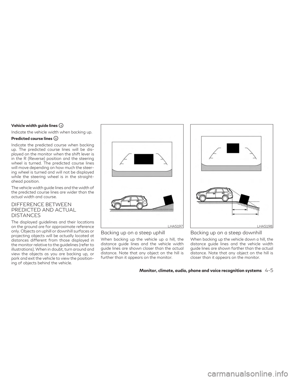
Vehicle width guide linesO4
Indicate the vehicle width when backing up.
Predicted course lines
O5
Indicate the predicted course when backing
up. The predicted course lines will be dis-
played on the monitor when the shift lever is
in the R (Reverse) position and the steering
wheel is turned. The predicted course lines
will move depending on how much the steer-
ing wheel is turned and will not be displayed
while the steering wheel is in the straight-
ahead position.
The vehicle width guide lines and the width of
the predicted course lines are wider than the
actual width and course.
DIFFERENCE BETWEEN
PREDICTED AND ACTUAL
DISTANCES
The displayed guidelines and their locations
on the ground are for approximate reference
only. Objects on uphill or downhill surfaces or
projecting objects will be actually located at
distances different from those displayed in
the monitor relative to the guidelines (refer to
illustrations). When in doubt, turn around and
view the objects as you are backing up, or
park and exit the vehicle to view the position-
ing of objects behind the vehicle.
Backing up on a steep uphill
When backing up the vehicle up a hill, the
distance guide lines and the vehicle width
guide lines are shown closer than the actual
distance. Note that any object on the hill is
further than it appears on the monitor.
Backing up on a steep downhill
When backing up the vehicle down a hill, the
distance guide lines and the vehicle width
guide lines are shown farther than the actual
distance. Note that any object on the hill is
closer than it appears on the monitor.
LHA5197LHA5198
Monitor, climate, audio, phone and voice recognition systems4-5
Page 276 of 636
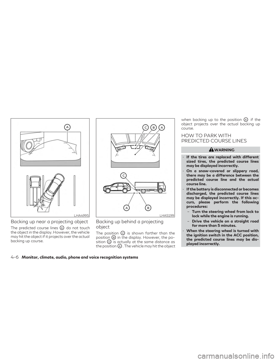
Backing up near a projecting object
The predicted course linesOAdo not touch
the object in the display. However, the vehicle
may hit the object if it projects over the actual
backing up course.
Backing up behind a projecting
object
The positionOCis shown farther than the
position
OBin the display. However, the po-
sition
OCis actually at the same distance as
the position
OA. The vehicle may hit the object when backing up to the position
OAif the
object projects over the actual backing up
course.
HOW TO PARK WITH
PREDICTED COURSE LINES
WARNING
• If the tires are replaced with different
sized tires, the predicted course lines
may be displayed incorrectly.
• On a snow-covered or slippery road,
there may be a difference between the
predicted course line and the actual
course line.
• If the battery is disconnected or becomes
discharged, the predicted course lines
may be displayed incorrectly. If this oc-
curs, please perform the following
procedures:
– Turn the steering wheel from lock to
lock while the engine is running.
– Drive the vehicle on a straight road
for more than 5 minutes.
• When the steering wheel is turned with
the ignition switch in the ACC position,
the predicted course lines may be dis-
played incorrectly.
LHA4995LHA5199
4-6Monitor, climate, audio, phone and voice recognition systems
Page 277 of 636
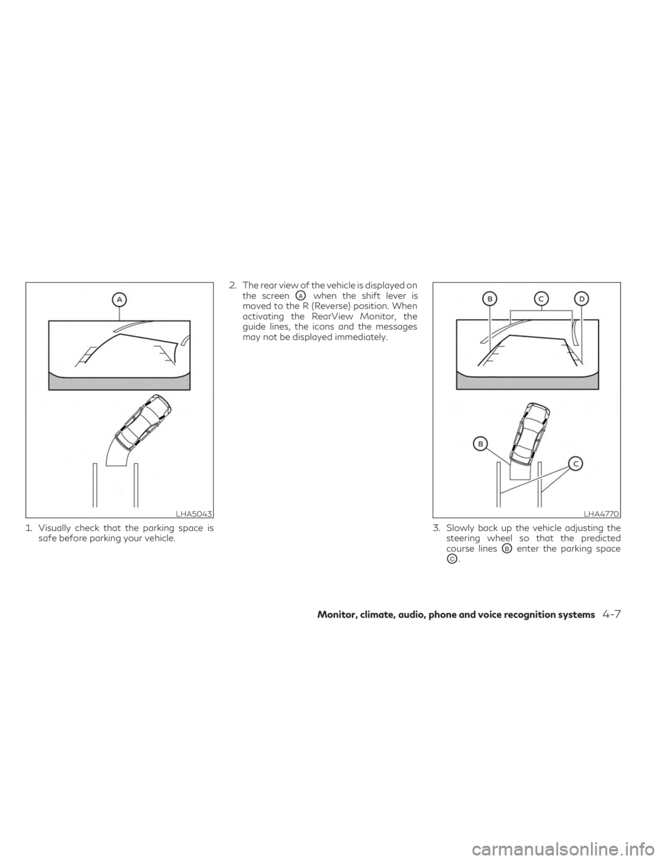
1. Visually check that the parking space issafe before parking your vehicle. 2. The rear view of the vehicle is displayed on
the screen
OAwhen the shift lever is
moved to the R (Reverse) position. When
activating the RearView Monitor, the
guide lines, the icons and the messages
may not be displayed immediately.
3. Slowly back up the vehicle adjusting thesteering wheel so that the predicted
course lines
OBenter the parking space
OC.
LHA5043LHA4770
Monitor, climate, audio, phone and voice recognition systems4-7
Page 278 of 636
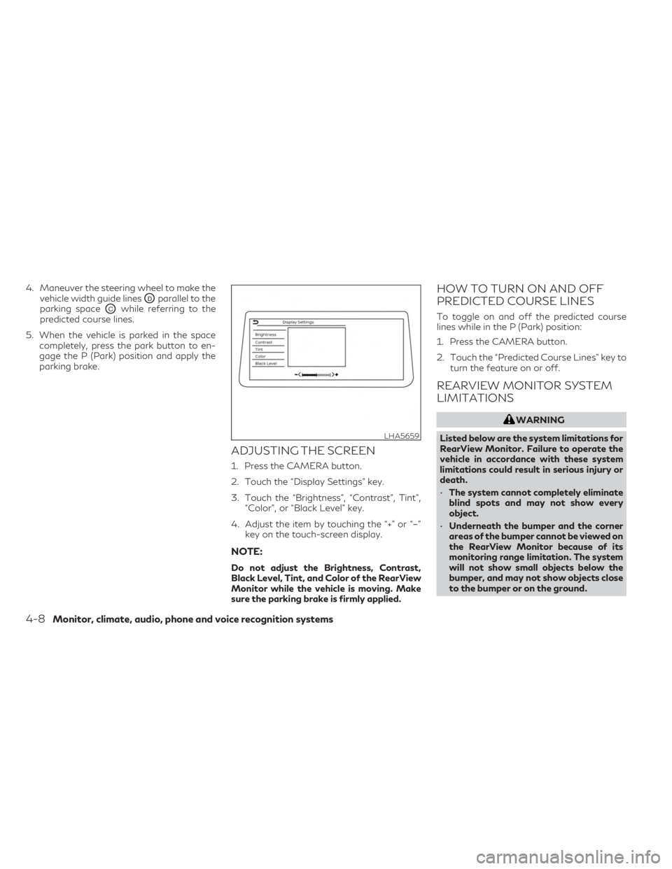
4. Maneuver the steering wheel to make thevehicle width guide lines
ODparallel to the
parking space
OCwhile referring to the
predicted course lines.
5. When the vehicle is parked in the space completely, press the park button to en-
gage the P (Park) position and apply the
parking brake.
ADJUSTING THE SCREEN
1. Press the CAMERA button.
2. Touch the “Display Settings” key.
3. Touch the “Brightness”, “Contrast”, Tint”, “Color”, or “Black Level” key.
4. Adjust the item by touching the “+” or “–” key on the touch-screen display.
NOTE:
Do not adjust the Brightness, Contrast,
Black Level, Tint, and Color of the RearView
Monitor while the vehicle is moving. Make
sure the parking brake is firmly applied.
HOW TO TURN ON AND OFF
PREDICTED COURSE LINES
To toggle on and off the predicted course
lines while in the P (Park) position:
1. Press the CAMERA button.
2. Touch the “Predicted Course Lines” key toturn the feature on or off.
REARVIEW MONITOR SYSTEM
LIMITATIONS
WARNING
Listed below are the system limitations for
RearView Monitor. Failure to operate the
vehicle in accordance with these system
limitations could result in serious injury or
death.
• The system cannot completely eliminate
blind spots and may not show every
object.
• Underneath the bumper and the corner
areas of the bumper cannot be viewed on
the RearView Monitor because of its
monitoring range limitation. The system
will not show small objects below the
bumper, and may not show objects close
to the bumper or on the ground.
LHA5659
4-8Monitor, climate, audio, phone and voice recognition systems
Page 283 of 636
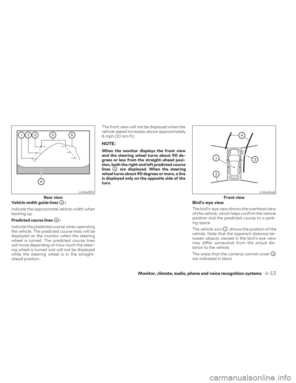
Vehicle width guide linesO5:
Indicate the approximate vehicle width when
backing up.
Predicted course lines
O6:
Indicate the predicted course when operating
the vehicle. The predicted course lines will be
displayed on the monitor when the steering
wheel is turned. The predicted course lines
will move depending on how much the steer-
ing wheel is turned and will not be displayed
while the steering wheel is in the straight-
ahead position. The front view will not be displayed when the
vehicle speed increases above approximately
6 mph (10 km/h).
NOTE:
When the monitor displays the front view
and the steering wheel turns about 90 de-
grees or less from the straight-ahead posi-
tion, both the right and left predicted course
lines
O6are displayed. When the steering
wheel turns about 90 degrees or more, a line
is displayed only on the opposite side of the
turn.
Bird’s-eye view
The bird's-eye view shows the overhead view
of the vehicle, which helps confirm the vehicle
position and the predicted course to a park-
ing space.
The vehicle icon
O1shows the position of the
vehicle. Note that the apparent distance be-
tween objects viewed in the bird's-eye view
may differ somewhat from the actual dis-
tance to the vehicle.
The areas that the cameras cannot cover
O2
are indicated in black.
LHA4992
Rear view
LHA4546
Front view
Monitor, climate, audio, phone and voice recognition systems4-13
Page 284 of 636

The non-viewable areaO2is highlighted in
yellow for several seconds after the bird’s-
eye view is displayed. It will be shown only the
first time after the ignition switch is placed in
the ON position.
The driver can check the approximate direc-
tion and angle of the tire on the display by the
tire icon
O3when driving the vehicle forward
or backward. Predicted course lines
O4indicate the pre-
dicted course when operating the vehicle.
The predicted course lines will be displayed
on the monitor when the steering wheel is
turned. The predicted course lines will move
depending on how much the steering wheel is
turned and will not be displayed while the
steering wheel is in the neutral position.
When the monitor displays the front view and
the steering wheel turns about 90 degrees or
less from the neutral position, the two green
predicted course lines are shown in front of
the vehicle.
When the steering wheel turns about 90 de-
grees or more, one green predicted course
line is shown in front of the vehicle and the
other predicted course line is shown at the
side of the vehicle.
When the monitor displays the rear view, the
predicted course lines are shown at the back
of the vehicle.WARNING
• Objects in the bird's-eye view will appear
further than the actual distance.
• Tall objects, such as a curb or vehicle,
may be misaligned or not displayed at
the seam of the views.
• Objects that are above the camera can-
not be displayed.
• The view of the bird's-eye view may be
misaligned when the camera position
alters.
• A line on the ground may be misaligned
and is not seen as being straight at the
seam of the views. The misalignment will
increase as the line proceeds away from
the vehicle.
• Tire angle display does not indicate the
actual tire angle.
LHA4547
Rear view
4-14Monitor, climate, audio, phone and voice recognition systems