climate control INFINITI QX60 2023 Owners Manual
[x] Cancel search | Manufacturer: INFINITI, Model Year: 2023, Model line: QX60, Model: INFINITI QX60 2023Pages: 636, PDF Size: 7.28 MB
Page 15 of 636
Table of
contentsIllustrated table of contents
Safety-Seats, seat belts and supplemental restraint system
Instruments and controls
Pre-driving checks and adjustments
Monitor, climate, audio, phone and voice recognition systems
Starting and driving
In case of emergency
Appearance and care
Do-it-yourself
Maintenance and schedules
Technical and consumer information
Index
0
1
2
3
4
5
6
7
8
9
10
11
Page 22 of 636
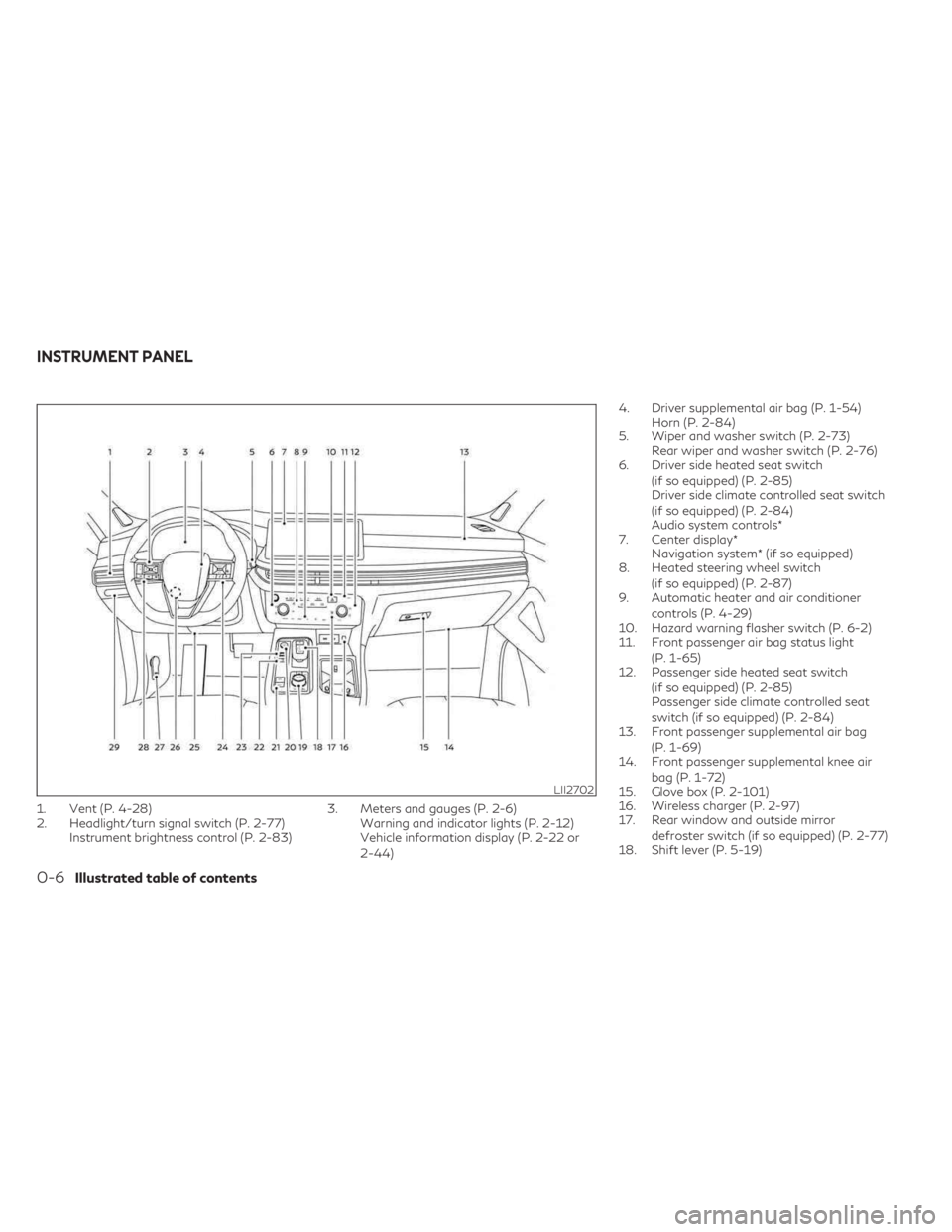
1. Vent (P. 4-28)
2. Headlight/turn signal switch (P. 2-77)Instrument brightness control (P. 2-83) 3. Meters and gauges (P. 2-6)
Warning and indicator lights (P. 2-12)
Vehicle information display (P. 2-22 or
2-44) 4. Driver supplemental air bag (P. 1-54)
Horn (P. 2-84)
5. Wiper and washer switch (P. 2-73) Rear wiper and washer switch (P. 2-76)
6. Driver side heated seat switch
(if so equipped) (P. 2-85)
Driver side climate controlled seat switch
(if so equipped) (P. 2-84)
Audio system controls*
7. Center display* Navigation system* (if so equipped)
8. Heated steering wheel switch
(if so equipped) (P. 2-87)
9. Automatic heater and air conditioner
controls (P. 4-29)
10. Hazard warning flasher switch (P. 6-2)
11. Front passenger air bag status light
(P. 1-65)
12. Passenger side heated seat switch
(if so equipped) (P. 2-85)
Passenger side climate controlled seat
switch (if so equipped) (P. 2-84)
13. Front passenger supplemental air bag
(P. 1-69)
14. Front passenger supplemental knee air
bag (P. 1-72)
15. Glove box (P. 2-101)
16. Wireless charger (P. 2-97)
17. Rear window and outside mirror
defroster switch (if so equipped) (P. 2-77)
18. Shift lever (P. 5-19)
LII2702
INSTRUMENT PANEL
0-6Illustrated table of contents
Page 104 of 636

Climate controlled seat switches
(if so equipped)................................ 2-84
Heated seat switches (if so equipped) ...........2-85
Heated 2nd row seat switches (if so equipped) . . 2-86
Heated steering wheel switch (if so equipped) . . . 2-87
Steering Assist switch (for vehicles with
ProPILOT Assist) (if so equipped) ...............2-88
Seat massage switch (if so equipped) ...........2-88
Head Up Display (HUD) (if so equipped) .........2-89
HowtousetheHUD........................ 2-90
Driver Assistance/Navigation linking .........2-91
Emergency call (SOS) button ...................2-92
Rear Door Alert ................................ 2-92
Power outlets ................................. 2-94
12v outlets ................................. 2-94
120v outlet (if so equipped) .................2-95
USB/iPod® charging ports .....................2-96
Wireless charger ............................... 2-97
Wireless charger indicator ...................2-98
Wireless charger operation ..................2-98
Extended storage switch .......................2-99
Storage ...................................... 2-100
Front-door pockets ........................ 2-100Lower console storage tray
................2-100
Seatback pockets .......................... 2-101
Glove box .................................. 2-101
Console box ............................... 2-102
Second row console (if so equipped) ........2-102
Overhead sunglasses storage ...............2-103
Cup holders ................................ 2-104
Cargo area storage bin .....................2-106
Luggage hooks ............................ 2-106
Roof rack (if so equipped) ..................2-107
Windows ..................................... 2-108
Power windows ........................... 2-108
Rear door sunshade (if so equipped) ........2-111
Power moonroof ............................. 2-111
Automatic moonroof and sunshade .........2-112
Interior
lights ................................. 2-114
Console light ............................... 2-114
Map lights ................................. 2-115
Personal lights ............................. 2-115
Cargo light ................................ 2-115
HomeLink® Universal Transceiver
(if so equipped) ............................... 2-116
Programming HomeLink® ..................2-116
Page 106 of 636
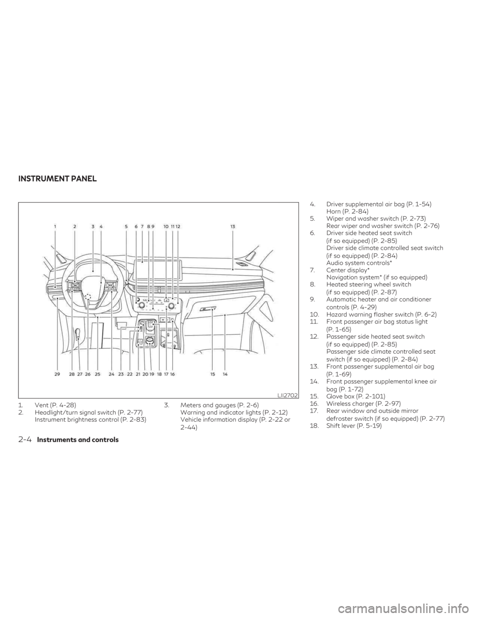
1. Vent (P. 4-28)
2. Headlight/turn signal switch (P. 2-77)Instrument brightness control (P. 2-83) 3. Meters and gauges (P. 2-6)
Warning and indicator lights (P. 2-12)
Vehicle information display (P. 2-22 or
2-44) 4. Driver supplemental air bag (P. 1-54)
Horn (P. 2-84)
5. Wiper and washer switch (P. 2-73) Rear wiper and washer switch (P. 2-76)
6. Driver side heated seat switch
(if so equipped) (P. 2-85)
Driver side climate controlled seat switch
(if so equipped) (P. 2-84)
Audio system controls*
7. Center display* Navigation system* (if so equipped)
8. Heated steering wheel switch
(if so equipped) (P. 2-87)
9. Automatic heater and air conditioner
controls (P. 4-29)
10. Hazard warning flasher switch (P. 6-2)
11. Front passenger air bag status light
(P. 1-65)
12. Passenger side heated seat switch
(if so equipped) (P. 2-85)
Passenger side climate controlled seat
switch (if so equipped) (P. 2-84)
13. Front passenger supplemental air bag
(P. 1-69)
14. Front passenger supplemental knee air
bag (P. 1-72)
15. Glove box (P. 2-101)
16. Wireless charger (P. 2-97)
17. Rear window and outside mirror
defroster switch (if so equipped) (P. 2-77)
18. Shift lever (P. 5-19)
LII2702
INSTRUMENT PANEL
2-4Instruments and controls
Page 186 of 636
Move the lever up or down until the turn
signal begins to flash, but the lever does not
latch, and release the lever. The turn signal
will automatically flash three times.
Choose the appropriate method to signal a
lane change based on road and traffic
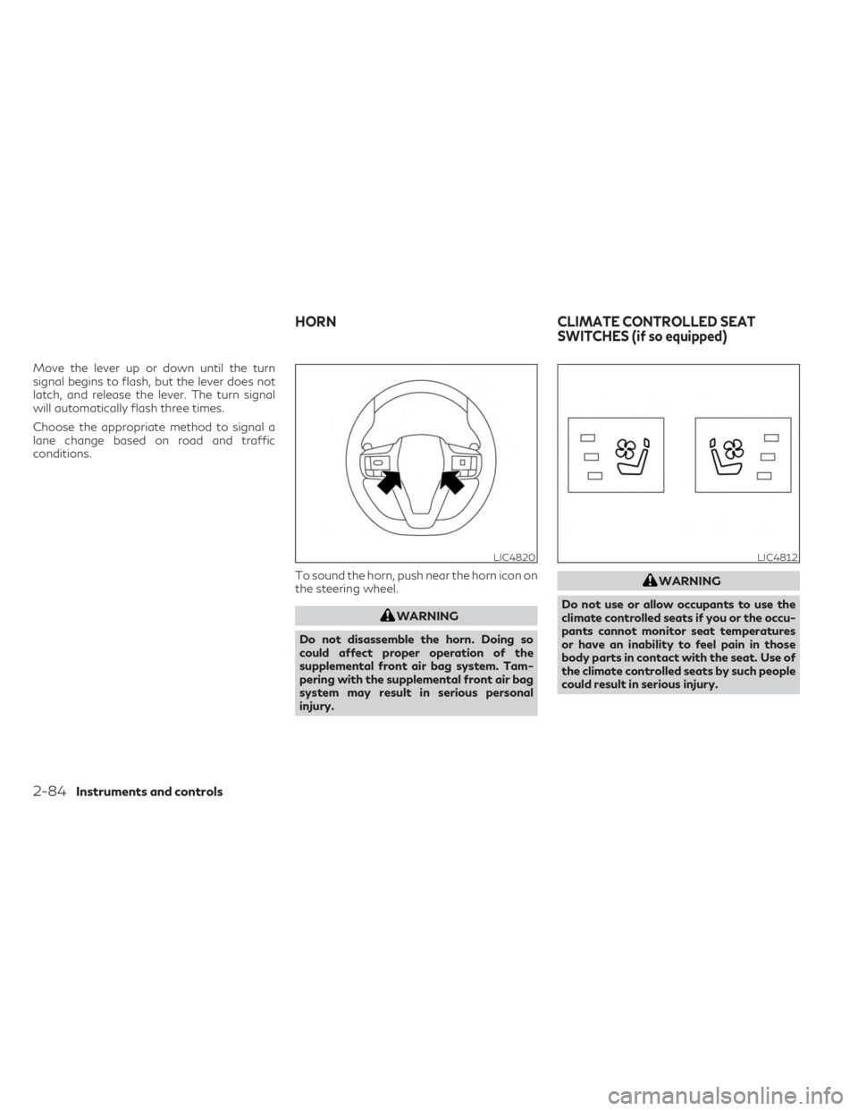
conditions.To sound the horn, push near the horn icon on
the steering wheel.
WARNING
Do not disassemble the horn. Doing so
could affect proper operation of the
supplemental front air bag system. Tam-
pering with the supplemental front air bag
system may result in serious personal
injury.
WARNING
Do not use or allow occupants to use the
climate controlled seats if you or the occu-
pants cannot monitor seat temperatures
or have an inability to feel pain in those
body parts in contact with the seat. Use of
the climate controlled seats by such people
could result in serious injury.
LIC4820LIC4812
HORN CLIMATE CONTROLLED SEAT
SWITCHES (if so equipped)
2-84Instruments and controls
Page 187 of 636
CAUTION
• The battery could run down if the climate
control seat is operated while the engine
is not running.
• Do not use the climate control seat for
extended periods or when no one is using
the seat.
• Do not put anything on the seat which
insulates heat, such as a blanket, cush-
ion, seat cover, etc. Otherwise, the seat
may become overheated.
• Do not place anything hard or heavy on
the seat or pierce it with a pin or similar
objects. This may result in damage to the
climate controlled seat.
• Any liquid spilled on the seat should be
removed immediately with a dry cloth
• When cleaning the seat, never use gaso-
line, benzine, thinner, or any similar
materials.
• If any malfunctions are found or the cli-
mate controlled seat does not operate,
turn the switch off and have the system
checked. It is recommended that you
visit an INFINITI retailer for this service. The climate controlled seats cool down the
front seats by ventilating air into the seats.
The climate control switch is located by the
air conditioning controls.
The climate controlled seat can be operated
as follows:
1. Start the engine.
2. Press the switch to adjust the desired in-
tensity. The indicator light on the switch
will illuminate.
3. When the vehicle's interior is cooled, or before you leave the vehicle, be sure to
press the switch to turn off the climate
controlled seats. The indicator light on the
switch will turn off.
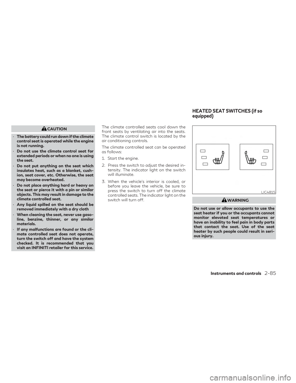
WARNING
Do not use or allow occupants to use the
seat heater if you or the occupants cannot
monitor elevated seat temperatures or
have an inability to feel pain in body parts
that contact the seat. Use of the seat
heater by such people could result in seri-
ous injury.
LIC4815
HEATED SEAT SWITCHES (if so
equipped)
Instruments and controls2-85
Page 198 of 636

1. Type-C USB
2. Type-A USB
There are USB/iPod® charging ports located
in 1st row, two in the front media pocket
below the climate controls and one in the
console box, in the 2nd row on the back of the
center console and in the 3rd row by the cup
holders. These ports will charge compatible
devices.NOTE:
• Not all of the USB/iPod® charging portswill operate with the display screen. Only
the USB connection ports located under
the climate controls will allow operation of
USB/iPod® devices through the audio
system.
• For best results, it is recommended to use the manufacturer cables, which are sold
separately. A USB Type-A to USB Type-C
adapter can also be purchased separately;
however, results may vary.CAUTION
• Do not force a USB device into the con-
nector. Inserting the USB device tilted or
up-side down into the connector may
damage the connector. Make sure that
the USB device is connected correctly
into the connector.
• Do not use a reversible USB cable. Using
the reversible USB cable may damage
the connector.
LIC5029
1st row (below climate controls)
LIC5030
1st row (inside the console box)
LIC5031
2nd row
USB/iPod® CHARGING PORTS
2-96Instruments and controls
Page 244 of 636

Thebutton will be on the INFINITI
Intelligent Key if the vehicle has Remote En-
gine Start. This feature allows the engine to
start from outside the vehicle.
The following features may be affected
when the Remote Engine Start feature is
used:
• Vehicles with an automatic climate control system may default to either a heating or
cooling mode depending on outside and
cabin temperatures. For additional infor-
mation, see “Remote Engine Start with In-
telligent Climate Control” in the (P. 4-30). Laws in some local communities may restrict
or prohibit the use of Remote Engine Start, or
the amount of time a parked vehicle engine
may idle. For example, some laws require a
person using Remote Engine Start to have
the vehicle in view or may restrict idling time
except in freezing temperatures. Check local
regulations for any requirements.
Other conditions may affect the function of
the Remote Engine Start feature. For addi-
tional information, see “Conditions the Re-
mote Engine Start will not work” (P. 3-20).
Other conditions can affect the performance
of the Intelligent Key transmitter. For addi-
tional information, see “INFINITI Intelligent
Key” (P. 3-2).
REMOTE ENGINE START
OPERATING RANGE
WARNING
• To help avoid risk of injury or death
through unintended operation of the ve-
hicle and/or its systems, including en-
trapment in windows or inadvertent
door lock activation, do not leave chil-
dren, people who require the assistance
of others or pets unattended in your ve-
hicle. Additionally, the temperature in-
side a closed vehicle on a warm day can
quickly become high enough to cause a
significant risk of injury or death to
people and pets.
• Do not use Remote Engine Start in closed
spaces such as a garage. Do not breathe
exhaust gases; they contain colorless
and odorless carbon monoxide. Carbon
monoxide is dangerous. It can cause un-
consciousness or death.
LPD2995
REMOTE ENGINE START (if so
equipped)
3-18Pre-driving checks and adjustments
Page 245 of 636

CAUTION
When the Intelligent Key battery is dis-
charged or other strong radio wave
sources are present near the operating lo-
cation, the Intelligent Key operating range
becomes narrower, and the Intelligent Key
may not function properly.
The Remote Engine Start function can only
be used when the Intelligent Key is within the
specified operating range from the vehicle.
The Remote Engine Start operating range is
approximately 197 ft (60 m) from the vehicle.
REMOTE STARTING THE
VEHICLE
To use the Remote Engine Start feature per-
form the following:
1. Aim the Intelligent Key at the vehicle.
2. Press the
button to lock all doors.
3. Within 5 seconds press and hold the
button until the turn signal lights flash and
the tail lamps turn on. If the vehicle is not
within view press and hold the
but-
ton for at least 2 seconds. The following events will occur when the en-
gine starts:
• The parking lights will turn on and remain
on as long as the engine is running.
• The doors will be locked and the climate control system may come on.
• The engine will continue to run for 10 min- utes. Repeat the steps to extend the time
for an additional 10 minutes. For additional
information, see “Extending engine run
time” (P. 3-19).
Press and hold the brake pedal while switch-
ing the ignition to the ON position before
driving. For additional information, see “Driv-
ing the vehicle” (P. 5-18).
EXTENDING ENGINE RUN TIME
The Remote Engine Start feature can be ex-
tended one time by performing the steps
listed in “Remote starting the vehicle”
(P. 3-19). Run time will be calculated as
follows:
• The first 10 minute run time will start when the Remote Engine Start function is
performed. • The second 10 minutes will start immedi-
ately when the Remote Engine Start func-
tion is performed again. For example, if the
engine has been running for 5 minutes, and
10 minutes are added, the engine will run
for a total of 15 minutes.
• Extending engine run time will bring you to the two Remote Engine Start limit.
A maximum of two Remote Engine Starts, or
a single start with an extension, are allowed
between ignition cycles.
The vehicle must be driven at speeds of 4
mph (7 km/h) before the remote engine start
procedure can be used again.
CANCELING A REMOTE ENGINE
START
To cancel a Remote Engine Start, perform
one of the following:
• Aim the Intelligent Key at the vehicle and press
until the parking lights turn off.
• Turn on the hazard warning flashers.
• Cycle the ignition switch on and then off.
• The extended engine run time has expired.
• The first 10 minute timer has expired.
• Opening the engine hood.
• Shifting the vehicle out of P (Park).
Pre-driving checks and adjustments3-19
Page 271 of 636
4 Monitor, climate, audio, phone and voice
recognition systems
INFINITI InTouch™ Owner’s Manual..............4-2
RearView Monitor (if so equipped) ................4-3
RearView Monitor system operation ...........4-4
How to read the displayed lines ................4-4
Difference between predicted and actual
distances .....................................4-5
How to park with predicted course lines .......4-6
Adjusting the screen ......................... 4-8
How to turn on and off predicted course
lines ......................................... 4-8
RearView Monitor system limitations ......... 4-8
System maintenance ..........................4-9
Around View® Monitor (if so equipped) .........4-10
Around View® Monitor system operation .....4-11
Difference between predicted and actual
distances ................................... 4-16
How to park with predicted course lines ......4-17
How to switch the display ...................4-19
Adjusting the screen ........................ 4-19
Around View® Monitor system
limitations .................................. 4-20System maintenance
........................ 4-22
Moving Object Detection (MOD)
(if so equipped) ................................ 4-23
MOD system operation .....................4-24
Turning MOD on and off ....................4-26
MOD system limitations .....................4-26
System maintenance ........................ 4-27
Vents .......................................... 4-28
Heater and air conditioner (automatic) ..........4-29
Automatic operation ........................ 4-30
Manual operation ........................... 4-31
Operating tips .............................. 4-32
Automatic Climate Control System
(if so equipped) ............................. 4-33
Rear automatic air conditioning system ......4-34
Servicing air conditioner ........................ 4-36
Antenna ....................................... 4-36
Car phone or CB radio ......................... 4-37
iPod®/iPhone® ................................ 4-37