key battery INFINITI QX80 2014 User Guide
[x] Cancel search | Manufacturer: INFINITI, Model Year: 2014, Model line: QX80, Model: INFINITI QX80 2014Pages: 578, PDF Size: 2.8 MB
Page 179 of 578

3-14Pre-driving checks and adjustments
SymptomPossible causeAction to take
When pushing the ignition switch
to start the engine The Intelligent Key battery indicator appears
on the display.
The battery charge is low.Replace the battery with a new one. (See
“Battery”
in the“8. Maintenance and do-it-
yourself” section.)
The NO KEY warning appears on the display
and the inside warning chime sounds for a few
seconds. The Intelligent Key is not in the vehicle. Carry the Intelligent Key with you.
When pushing the ignition switch The Intelligent Key system warning light in the
meter illuminates in yellow. It warns of a malfunction with the
Intelligent Key system.
Contact an INFINITI retailer.
Page 180 of 578

WARNING
The Intelligent Key transmits radio waves
when the buttons are pushed. The FAA
advises that radio waves may affect aircraft
navigation and communication systems. Do
not operate the Intelligent Key while on an
airplane. Make sure the buttons are not
operated unintentionally when the unit is
stored for a flight.
It is possible to lock/unlock all doors, fuel-
filler door, activate the panic alarm and
open the windows by pushing the buttons
on the Intelligent Key from outside the
vehicle.
Before locking the doors, make sure the
Intelligent Key is not left in the vehicle.
The LOCK/UNLOCK button on the Intelli-
gent Key can operate at a distance of
approximately 33 ft (10 m) from the
vehicle. (The effective distance depends
upon the conditions around the vehicle.)
As many as 4 Intelligent Keys can be used
with one vehicle. For information concern-
ing the purchase and use of additional
Intelligent Keys, contact an INFINITI retai-
ler.The lock and unlock buttons on the
Intelligent Key will not operate when:
.
the distance between the Intelligent Key
and the vehicle is over 33 ft (10 m).
. the Intelligent Key battery runs down.
After locking with the remote keyless entry
function, pull the door handle to make sure
the doors are securely locked.
The LOCK/UNLOCK operating range varies
depending on the environment. To securely
operate the lock and unlock buttons,
approach the vehicle to about 3 ft (1 m)
from the door.SPA2718
Type A
JVP0156X
Type B
Pre-driving checks and adjustments3-15
REMOTE KEYLESS ENTRY SYSTEM
Page 182 of 578

The power lift gate buttoncannot be
operated when the ignition switch is in the
ON position.
Using panic alarm
If you are near your vehicle and feel
threatened, you may activate the alarm to
call attention as follows:
1. Push the PANIC
button*Don the
Intelligent Key for more than 1 second.
2. The theft warning alarm and headlights will stay on for 25 seconds.
3. The panic alarm stops when:
.It has run for 25 seconds, or.Any of the buttons on the Intelligent Key are pushed. (Note: Panic button
or power lift gate button should be
pushed for more than 1 second.)
Remote engine start (if so
equipped)
The remote engine startbutton*Eis
on the Intelligent Key if the vehicle has
remote engine start function. This function
allows the engine to start from outside the
vehicle.
Some systems, such as the air conditioner
system, will turn on during a remote start,
if the system was on the last time the ignition switch was turned off.
Laws in some local communities may
restrict the use of remote starters. For
example, some laws require a person using
remote start to have the vehicle in view.
Check local regulations for any require-
ments.
Other conditions may affect the remote
engine start function. See
“Conditions the
remote engine start will not work” later in
this section.
Other conditions can affect the perfor-
mance of the Intelligent Key transmitter.
See “Intelligent Key system” earlier in this
section.
Remote engine start operating range:
The remote engine start function can only
be used when the Intelligent Key is within
the specified operating range from the
vehicle.
When the Intelligent Key battery is dis-
charged or strong radio waves are present
near the operating location, the Intelligent
Key operating range becomes narrower,
and the Intelligent Key may not function
properly.
The remote engine start operating range is
approximately 197 ft (60 m) from the vehicle.
Operating a remote engine start:
To use the remote start function to start the
engine, perform the following:
1. Aim the Intelligent Key at the vehicle.
2. Push the LOCK
button to lock all
doors.
3. Within 5 seconds push and hold the remote engine start
button until
the turn signal lights illuminate. If the
vehicle is not within view, push and
hold the remote engine start
button for about 2 seconds.
The following events will occur when the
engine starts:
. The front parking lights will turn on and
remain on as long as the engine is
running.
. The doors will be locked and the air
conditioner system may turn on.
. The engine will continue to run for
about 10 minutes. Repeat the steps to
extend the time for an additional 10
minutes. See “Extending engine run
time” later in this section.
Depress the brake pedal and place the
ignition switch in the ON position before
Pre-driving checks and adjustments3-17
Page 186 of 578
SPA2774
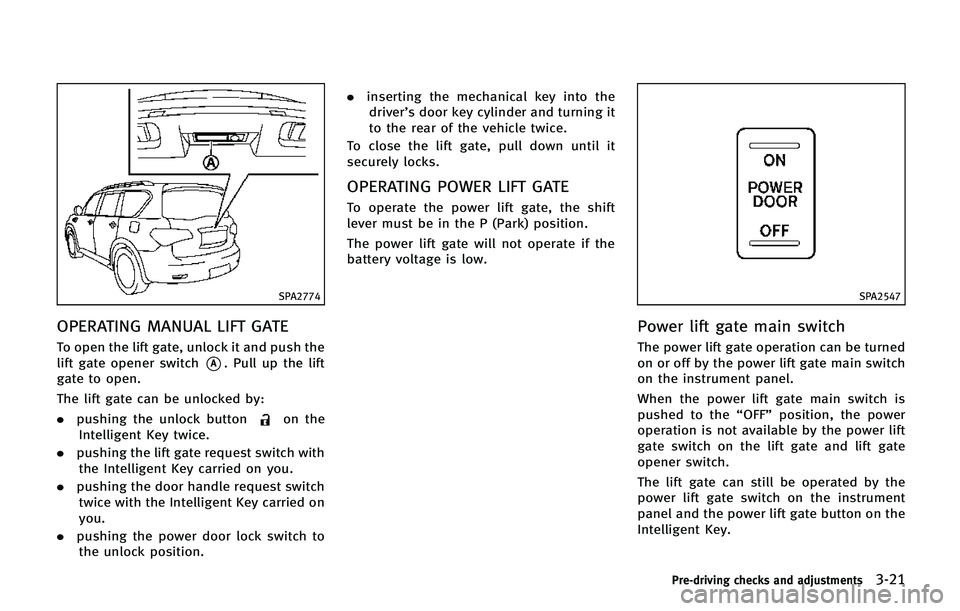
OPERATING MANUAL LIFT GATE
To open the lift gate, unlock it and push the
lift gate opener switch
*A. Pull up the lift
gate to open.
The lift gate can be unlocked by:
. pushing the unlock button
on the
Intelligent Key twice.
. pushing the lift gate request switch with
the Intelligent Key carried on you.
. pushing the door handle request switch
twice with the Intelligent Key carried on
you.
. pushing the power door lock switch to
the unlock position. .
inserting the mechanical key into the
driver’s door key cylinder and turning it
to the rear of the vehicle twice.
To close the lift gate, pull down until it
securely locks.
OPERATING POWER LIFT GATE
To operate the power lift gate, the shift
lever must be in the P (Park) position.
The power lift gate will not operate if the
battery voltage is low.
SPA2547
Power lift gate main switch
The power lift gate operation can be turned
on or off by the power lift gate main switch
on the instrument panel.
When the power lift gate main switch is
pushed to the “OFF”position, the power
operation is not available by the power lift
gate switch on the lift gate and lift gate
opener switch.
The lift gate can still be operated by the
power lift gate switch on the instrument
panel and the power lift gate button on the
Intelligent Key.
Pre-driving checks and adjustments3-21
Page 188 of 578

.pushing the power lift gate switch*D
on the lower part of the lift gate
The hazard flashes 4 times and the outside
chime sounds when the lift gate starts
closing.
NOTE:
When the lift gate is closed, it remains
unlocked. Manually lock the lift gate.
Reverse function
The power lift gate will reverse immediately
if one of the following actions is performed
during power open or power close.
. pushing the power lift gate switch
*A
on the instrument panel
. pushing the lift gate button
*C
on the Intelligent Key.
. pushing the lift gate switch
*Don the
lower part of the lift gate
The outside chime sounds when the lift
gate starts to reverse.
The power lift gate button
*Con the
Intelligent Key cannot be operated when
the ignition switch is in the ON position.
Auto reverse function
The auto-reverse function enables the lift
gate to automatically reverse when some- thing is caught in the lift gate as it is
opening or closing. When the control unit
detects an obstacle, the lift gate will
reverse and return to the full open or full
close position.
If a second obstacle is detected, the lift
gate motion will stop and the drive motor
will disengage. The lift gate will enter the
manual mode.
A pinch sensor is mounted on each side of
the lift gate. If an obstacle is detected by
the pinch sensor during power close, the
lift gate will reverse and return to the full
open position immediately.
NOTE:
If the pinch sensor is damaged or
removed, the power close function will
not operate.
WARNING
There is a small distance immediately before
the closed position that cannot be detected.
Make sure that all passengers keep their
hands, etc., clear from the lift gate opening
before closing the lift gate.
Manual mode
If power operation is not available, the lift
gate can be operated manually. Power
operation may not be available if multiple
obstacles have been detected in a single
power cycle or if the battery voltage is low.
When the power lift gate main switch is in
the OFF position, the lift gate can be
opened manually by pushing the lift gate
opener switch. If the power lift gate opener
switch is pushed during power open or
close, the power operation will be canceled
and the lift gate can be operated manually.
Pre-driving checks and adjustments3-23
Page 190 of 578

SPA2778
LIFT GATE RELEASE LEVER
If the lift gate cannot be opened with the
door lock switch due to a discharged
battery, follow these steps.
1. Remove the cover
*Ainside of the lift
gate using a suitable tool.
2. Move the lever
*Bas illustrated to
open the lift gate.
Contact an INFINITI retailer as soon as
possible for repair.
OPENING THE FUEL-FILLER DOOR
CAUTION
Lock all doors before going through auto-
matic car wash. Locking doors helps prevent
fuel-filler door from opening and becoming
damaged.
SPA2752
To open the fuel-filler door, unlock the fuel-
filler door by using one of the following
operations, then push the right side of the
door.
. Push the driver’s door handle request
switch with the Intelligent Key carried
with you.
. Push the passenger’ s door handle
request switch or lift gate request
switch twice with the Intelligent Key
carried with you.
. Push the UNLOCK button on the Intelli-
gent Key.
. Insert the mechanical key into the door
lock cylinder and rotate it towards the
Pre-driving checks and adjustments3-25
FUEL-FILLER DOOR
Page 198 of 578

SPA2756
SET/memory switches
The automatic drive positioner system has
three features:
. Entry/exit function
. Memory storage
. Setting memory function
ENTRY/EXIT FUNCTION
This system is designed so that the driver’s
seat and steering column will automati-
cally move when the automatic transmis-
sion shift lever is in the P (Park) position.
This allows the driver to get into and out of
the driver’s seat more easily.
The driver’s seat will slide backward and the steering wheel will move up when the
driver’s door is opened with the ignition
switch in the LOCK position.
The driver’s seat and steering wheel will
return to the previous positions when the
ignition switch is pushed to the ACC
position.
The driver’s seat will not return to the
previous positions if the seat or steering
adjusting switch is operated when the seat
is at the exit position.
Cancel or activate entry/exit func-
tion
The shift lever must be in the P (Park)
position with the ignition switch in the OFF
position.
The entry/exit function can be activated or
canceled by pressing and holding the SET
switch for more than 10 seconds.
The indicator lights on the memory
switches (1 and 2) will blink once when
the function is canceled, and the indicator
lights will blink twice when the function is
activated. Note that the indicator lights
may illuminate after 5 seconds while
holding the SET switch. This indicates
readiness for linking the Intelligent Key to
a stored memory position. Keep the SET switch pressed for more than 10 seconds
to turn on or off the entry/exit function.
The entry/exit function can also be acti-
vated or canceled if the
“Lift Steering
Wheel on Exit” key or“Slide Driver Seat
Back on Exit” key is turned to ON or OFF in
the “Comfort” settings. (See “Vehicle
information and settings” in the“4.
Monitor, climate, audio, phone and voice
recognition systems” section.)
Initialize entry/exit function
If the battery cable is disconnected, or if
the fuse opens, the entry/exit function will
not work though this function was set on
before. In such a case, after connecting the
battery or replacing with a new fuse, open
and close the driver’s door more than two
times after the ignition switch is turned
from the ON position to the LOCK position.
The entry/exit function will be activated.
Pre-driving checks and adjustments3-33
AUTOMATIC DRIVE POSITIONER
Page 199 of 578

3-34Pre-driving checks and adjustments
MEMORY STORAGE
Two positions for the driver’s seat, steering
column and outside mirrors can be stored
in the automatic drive positioner memory.
Follow these procedures to use the mem-
ory system.
1. Move the shift lever to the P (Park) position.
2. Push the ignition switch to the ON position.
3. Adjust the driver’s seat, steering col- umn and outside mirrors to the desired
positions by manually operating each
adjusting switch. For additional infor-
mation, see “Seats”in the“1. Safety —
seats, seat belts and supplemental
restraint system” section and“Tilt/
telescopic steering” earlier in this
section and “Outside mirrors” earlier
in this section.
4. Push the SET switch and, within 5 seconds, push the memory switch (1
or 2) fully for at least 1 second.
The indicator light for the pushed
memory switch will stay on for approxi-
mately 5 seconds after pushing the
switch.
If memory is stored in the same memory switch, the previous memory
will be deleted.
Linking Intelligent Key to a stored
memory position
The Intelligent Key can be linked to a
stored memory position with the following
procedure.
1. Follow the steps for storing a memory
position.
2. While the indicator light for the memory switch being set is illuminated for 5
seconds, push the
button on the
Intelligent Key. If the indicator light
blinks, the Intelligent Key is linked to
that memory setting.
Push the ignition switch to the OFF posi-
tion, and then push the
button on the
Intelligent Key. The driver’s seat, steering
wheel and outside mirrors will move to the
memorized position.
Confirming memory storage
. Push the ignition switch to the ON
position and push the SET switch. If
the main memory has not been stored,
the indicator light will come on for
approximately 0.5 second. When the
memory has stored in position, the indicator light will stay on for approxi-
mately 5 seconds.
. If the battery cable is disconnected, or if
the fuse opens, the memory will be
canceled. In this case, reset the desired
position using the previous procedure.
. If optional Intelligent Keys are added to
your vehicle, the memory storage pro-
cedure to switch 1 or 2 and linking
Intelligent Key procedure to a stored
memory position should be performed
again for each Intelligent Key. For
additional Intelligent Key information,
see “Keys” earlier in this section.
Selecting the memorized position
1. Move the shift lever to the P (Park)
position.
2. Use one of the following methods to move the driver’ s seat, the outside
mirrors and the steering wheel.
.Push the ignition switch to the ON position and push the memory
switch (1 or 2) fully for at least 1
second.
.Within 45 seconds of opening the
driver’ s door, push the memory
switch (1 or 2) fully for at least 1
second.
Page 263 of 578
4-62Monitor, climate, audio, phone and voice recognition systems
SEEK tuning:
. For AM and FM radio
Push the SEEK·CAT or TRACK button
orto tune from low to high or high
to low frequencies and to stop at the
next broadcasting station.
. For SiriusXM Satellite Radio
Push the SEEK·CAT or TRACK button
orto tune to the first channel of the
next or previous category.
During satellite radio reception, the follow-
ing notices will be displayed under certain
conditions.
. NO SIGNAL (No signal is received while
the SAT tuner is connected.)
. OFF AIR (Broadcasting signed off)
. CHECK ANTENNA (Antenna connection
error)
. LOADING (When the initial setting is
performed)
. UPDATING (When the satellite radio
subscription is not active)
. INVALID CH (Invalid channel is re-
ceived.)
SCAN tuning:
Push the SCAN tuning button to tune from low to high frequencies and stop at each
broadcasting station/channel for 5 sec-
onds. Pushing the button again during this
10 seconds period will stop SCAN tuning
and the radio will remain tuned to that
station/channel.
If the SCAN tuning button is not pushed
within 5 seconds, SCAN tuning moves to
the next station/channel.
*1to*6Station memory operations:
12 stations/channels can be set for the FM
band (6 each for FM1 and FM2), 18 for
SiriusXM Satellite Radio (6 each for XM1,
XM2 and XM3) and 6 stations can be set
for the AM band.
1. Choose the radio band using the radio band select button.
2. Tune to the desired station/channel using the SEEK·CAT, TRACK, SCAN
button or the radio TUNE knob.
3. Push and hold the desired station preset button
*1to*6until the radio
mutes.
4. The station indicator will then come on and the sound will resume. Memorizing
is now complete.
5. Other buttons can be set in the same manner.
If the battery cable is disconnected, or if
the fuse opens, the radio memory will be
erased. In that case, reset the desired
stations/channels.
Menu (SiriusXM Satellite Radio):
When the “Menu”key on the display is
selected while the SiriusXM Satellite Radio
is being played, the menu list will be
displayed.
The following items are available.
. Preset List
Displays the preset channel list. If 1 of
the 6 preset stations listed is touched
and held, the current station will be
stored as the new preset.
. Customize Channel List
Selects specific channels to skip while
using the TUNE, SEEK·CAT or Menu-
Categories feature.
. Favorite Artists & Songs
Stores the current artist or song that is
being played. Touch the “Alert”key to
be reminded when the stored artist or
song is playing on a station while
listening to SiriusXM Satellite Radio.
. Categories
Page 277 of 578
4-76Monitor, climate, audio, phone and voice recognition systems
Connected Devices:
Registered devices are shown on the list.
Select a Bluetooth device from the list, the
following options will be available.
.Select
Select “Select” to connect the selected
device to the vehicle. If there is a
different device currently connected,
the selected device will replace the
current device.
. Edit
Rename the selected Bluetooth device
using the keypad displayed on the
screen. (See “How to use touch screen”
earlier in this section.)
. Delete
Delete the selected Bluetooth device.
Edit Bluetooth Info:
Change the name broadcasted by this
system over Bluetooth. Change the PIN
code that is entered when connecting a
hands free device to this system.
Replace Connected Phone:
Replace the Bluetooth connection with a
connected Bluetooth cellular phone. For
details about Hands-Free Phone System,
see “Bluetooth
®Hands-Free Phone Sys- tem”
later in this section.
SAA3261
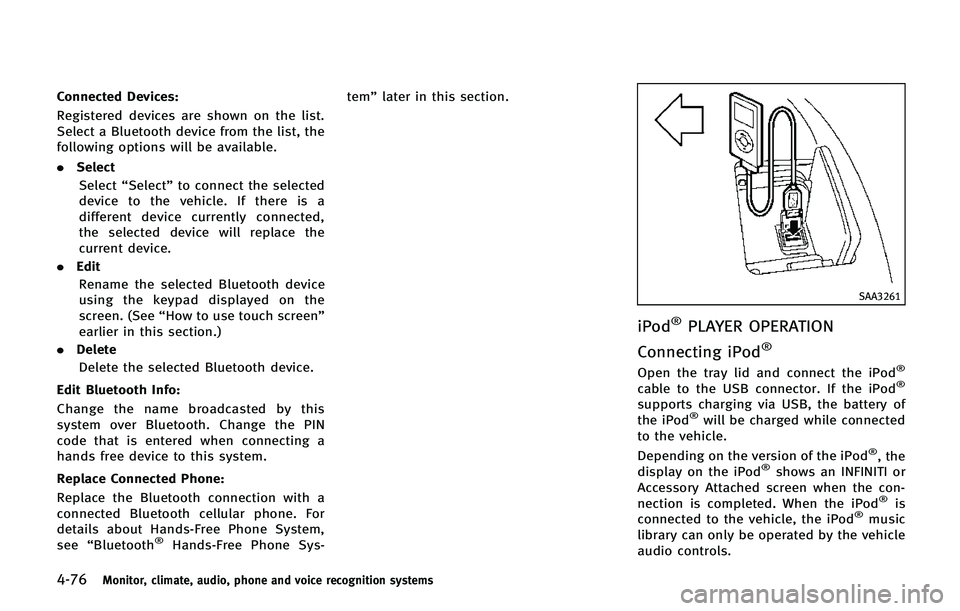
iPod®PLAYER OPERATION
Connecting iPod
®
Open the tray lid and connect the iPod®
cable to the USB connector. If the iPod®
supports charging via USB, the battery of
the iPod®will be charged while connected
to the vehicle.
Depending on the version of the iPod
®, the
display on the iPod®shows an INFINITI or
Accessory Attached screen when the con-
nection is completed. When the iPod
®is
connected to the vehicle, the iPod®music
library can only be operated by the vehicle
audio controls.