steering INFINITI QX80 2019 Owner's Guide
[x] Cancel search | Manufacturer: INFINITI, Model Year: 2019, Model line: QX80, Model: INFINITI QX80 2019Pages: 524, PDF Size: 2.45 MB
Page 209 of 524

SIC4448
VANITY MIRROR
To use the front vanity mirror, pull down the
sun visor and pull up the cover.
JVP0250X
SET/memory switches
The automatic drive positioner system has
three features:
. Entry/exit function
. Memory storage
. Setting memory function
ENTRY/EXIT FUNCTION
This system is designed so that the driver’s
seat and steering column will automatically
move when the automatic transmission shift
lever is in the P (Park) position. This allows
the driver to get into and out of the driver’s
seat more easily.
The driver’s seat will slide backward and the
steering wheel will move up when the
driver’s door is opened with the ignition
switch in the LOCK position.
The driver’s seat and steering wheel will
return to the previous positions when the
ignition switch is pushed to the ACC posi-
tion.
The driver’s seat will not return to the
previous positions if the seat or steering
adjusting switch is operated when the seat is
at the exit position.
Cancel or activate entry/exit func-
tion
The shift lever must be in the P (Park)
position with the ignition switch in the OFF
position.
The entry/exit function can be activated or
canceled by pressing and holding the SET
switch for more than 10 seconds.
The entry/exit function can also be acti-
vated or canceled if the “Lift Steering Wheel
Pre-driving checks and adjustments3-39
AUTOMATIC DRIVE POSITIONER
Page 210 of 524

3-40Pre-driving checks and adjustments
on Exit” key or “Slide Driver’s Seat Back on
Exit” key is turned to ON or OFF in the
Vehicle settings on the center display. (See
INFINITI InTouch
TMOwner’s Manual.)
Initialize entry/exit function
If the battery cable is disconnected, or if the
fuse opens, the entry/exit function will not
work though this function was set on before.
In such a case, after connecting the battery
or replacing with a new fuse, open and close
the driver’s door more than two times after
the ignition switch is turned from the ON
position to the LOCK position. The entry/
exit function will be activated.
MEMORY STORAGE
Two positions for the driver’s seat, steering
column and outside mirrors can be stored in
the automatic drive positioner memory.
Follow these procedures to use the memory
system.
1. Move the shift lever to the P (Park)position.
2. Adjust the driver’s seat, steering column and outside mirrors to the desired posi-
tions by manually operating each adjust-
ing switch. For additional information,
see “Seats” (P.1-3) and “Tilt/telescopic
steering” (P.3-29) and “Outside mirrors”
(P.3-37). 3. Push the SET switch and, within 5
seconds, push the memory switch (1 or
2) fully for at least 1 second.
The indicator light for the pushed mem-
ory switch will stay on for approximately
5 seconds after pushing the switch.
When the memory is stored in the
memory switch (1 or 2), a buzzer will
sound.
If memory is stored in the same memory
switch, the previous memory will be
deleted.
Linking Intelligent Key to a stored
memory position
The Intelligent Key can be linked to a stored
memory position with the following proce-
dure.
1. Follow the steps for storing a memoryposition.
2. While the indicator light for the memory switch being set is illuminated for 5
seconds, push the
button on the
Intelligent Key. If the indicator light
blinks, the Intelligent Key is linked to
that memory setting.
Push the ignition switch to the OFF position,
and then push the
button on the
Intelligent Key. The driver’s seat, steering
wheel and outside mirrors will move to the memorized position.
Confirming memory storage
.
Push the ignition switch to the ON
position and push the SET switch. If the
main memory has not been stored, the
indicator light will come on for approxi-
mately 0.5 second. When the memory
has stored in position, the indicator light
will stay on for approximately 5 seconds.
. If the battery cable is disconnected, or if
the fuse opens, the memory will be
canceled. In this case, reset the desired
position using the previous procedure.
. If optional Intelligent Keys are added to
your vehicle, the memory storage proce-
dure to switch 1 or 2 and linking
Intelligent Key procedure to a stored
memory position should be performed
again for each Intelligent Key. For addi-
tional Intelligent Key information, see
“Keys” (P.3-2).
Selecting the memorized position
1. Move the shift lever to the P (Park) position.
2. Use one of the following methods to move the driver’s seat, the outside
mirrors and the steering wheel.
.Push the memory switch (1 or 2) fully
for at least 1 second.
Page 211 of 524

The driver’s seat, steering column and
outside mirrors will move to the memor-
ized position or to the exit position when
the entry/exit function is set to active
with the indicator light flashing, and then
the light will stay on for approximately 5
seconds.
SETTING MEMORY FUNCTION
The status of the following settings can be
linked to the Intelligent Key and the memor-
ized settings can be available for each
Intelligent Key.
.Air conditioner system
. Navigation system
. Audio system
To use the memory function, lock the doors
with the Intelligent Key that is linked to the
settings.
To enable the memorized settings:
1. Carry the Intelligent Key that is linked to the settings, and unlock the doors by
pushing the driver’s door handle request
switch or “UNLOCK”
button on the
Intelligent Key.
2. Place the ignition switch in the ON position. “Connection with the key has
been done” will be displayed on the
screen and the memorized settings are
available (only when a new Intelligent
Key is used).
SYSTEM OPERATION
The automatic drive positioner system will
not work or will stop operating under the
following conditions:
.When the vehicle speed is above 0 MPH
(0 km/h) or 4 MPH (7 km/h) for some
limited functions such linking an Intelli-
gent Key to the vehicle when the power
source is turned on from off or during the
Exit function.
. When any of the memory switches are
pushed while the automatic drive posi-
tioner is operating.
. When the adjusting switch for the dri-
ver’s seat and steering column is turned
on while the automatic drive positioner is
operating.
. When the seat has already been moved
to the memorized position.
. When no seat position is stored in the
memory switch.
. When the shift lever is moved from the P
(Park) position to any other position.
Pre-driving checks and adjustments3-41
Page 218 of 524

4-6Monitor, climate, audio, phone and voice recognition systems
Front and rear view:
Guiding lines that indicate the approximate
vehicle width and distances to objects with
reference to the vehicle body line
are
displayed on the monitor.
Distance guide lines
Indicate distances from the vehicle body.
. Red line
: approx. 1.5 ft (0.5 m)
. Yellow line
: approx. 3 ft (1 m)
. Green line
: approx. 7 ft (2 m)
. Green line
(if so equipped): approx. 10
ft (3 m)
Vehicle width guide lines
Indicates the approximate vehicle width.
Predictive course lines
Indicate the predictive course when operat-
ing the vehicle. The predictive course lines
will be displayed on the monitor when the
steering wheel is turned. The predictive
course lines will move depending on how
much the steering wheel is turned and will
not be displayed while the steering wheel is
in the straight-ahead position.
The front view will not be displayed when
the vehicle speed is above 6 MPH (10 km/h).
NOTE:
When the monitor displays the front view
and the steering wheel turns about 90
degrees or less from the straight ahead position, both the right and left predictive
course lines
are displayed. When the
steering wheel turns about 90 degrees or
more, a line is displayed only on the
opposite side of the turn.
JVH1140X
Bird’s-eye view:
The bird’s-eye view shows the overhead
view of the vehicle, which helps confirm the
vehicle position and the predictive course to
a parking space.
The vehicle icon
shows the position of the
vehicle. Note that the size of the vehicle icon
on the bird’s-eye view may differ somewhat
from the actual distance to the vehicle.
The areas that the cameras cannot cover
are indicated in black.
The non-viewable area
is highlighted in
yellow for several seconds after the bird’s-
eye view is displayed. It will be shown only
the first time after the ignition switch is
placed in the ON position.
Page 219 of 524

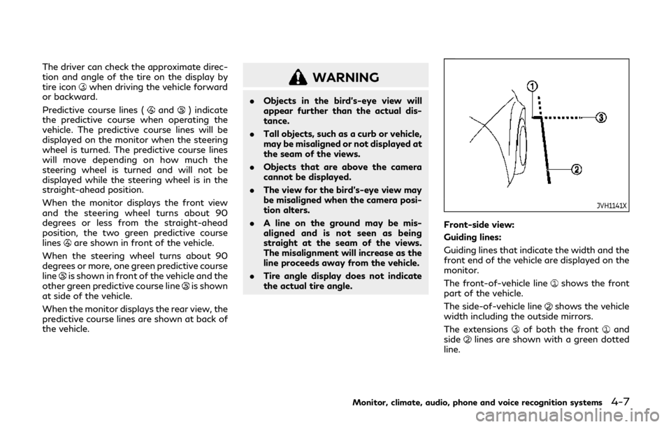
The driver can check the approximate direc-
tion and angle of the tire on the display by
tire icon
when driving the vehicle forward
or backward.
Predictive course lines (
and) indicate
the predictive course when operating the
vehicle. The predictive course lines will be
displayed on the monitor when the steering
wheel is turned. The predictive course lines
will move depending on how much the
steering wheel is turned and will not be
displayed while the steering wheel is in the
straight-ahead position.
When the monitor displays the front view
and the steering wheel turns about 90
degrees or less from the straight-ahead
position, the two green predictive course
lines
are shown in front of the vehicle.
When the steering wheel turns about 90
degrees or more, one green predictive course
line
is shown in front of the vehicle and the
other green predictive course lineis shown
at side of the vehicle.
When the monitor displays the rear view, the
predictive course lines are shown at back of
the vehicle.
WARNING
. Objects in the bird’s-eye view will
appear further than the actual dis-
tance.
. Tall objects, such as a curb or vehicle,
may be misaligned or not displayed at
the seam of the views.
. Objects that are above the camera
cannot be displayed.
. The view for the bird’s-eye view may
be misaligned when the camera posi-
tion alters.
. A line on the ground may be mis-
aligned and is not seen as being
straight at the seam of the views.
The misalignment will increase as the
line proceeds away from the vehicle.
. Tire angle display does not indicate
the actual tire angle.
JVH1141X
Front-side view:
Guiding lines:
Guiding lines that indicate the width and the
front end of the vehicle are displayed on the
monitor.
The front-of-vehicle line
shows the front
part of the vehicle.
The side-of-vehicle line
shows the vehicle
width including the outside mirrors.
The extensions
of both the frontand
sidelines are shown with a green dotted
line.
Monitor, climate, audio, phone and voice recognition systems4-7
Page 223 of 524

SAA1897
1. Visually check that the parking space issafe before parking your vehicle.
2. The rear view of the vehicle is displayed on the screen
when the shift lever is
moved to the R (Reverse) position.
SAA1898
3. Slowly back up the vehicle adjusting the steering wheel so that the predictive
course lines
enter the parking space.
4. Maneuver the steering wheel to make the vehicle width guide lines
parallel to
the parking spacewhile referring to
the predictive course lines. 5. When the vehicle is parked in the space
completely, move the shift lever to the P
(Park) position and apply the parking
brake.
Monitor, climate, audio, phone and voice recognition systems4-11
Page 253 of 524

4WD warning light ................................................. 5-126
Hill Start Assist system .............................................. 5-128
Parking/parking on hills .............................................. 5-129
TOW mode .................................................................... 5-130
SNOW mode ................................................................. 5-130
Power steering .............................................................. 5-131
Brake system .................................................................. 5-131 Braking precautions ................................................ 5-131
Parking brake break-in .......................................... 5-131
Brake assist .................................................................... 5-132 Brake assist ............................................................... 5-132
Anti-lock Braking System (ABS) ......................... 5-132 Vehicle Dynamic Control (VDC) system ................ 5-133
Vehicle Dynamic Control (VDC)
OFF switch ............................................................. 5-135
Cold weather driving .................................................. 5-136
Freeing a frozen door lock ................................ 5-136
Antifreeze ............................................................... 5-136
Battery .................................................................... 5-136
Draining of coolant water ................................. 5-136
Tire equipment ...................................................... 5-136
Special winter equipment .................................. 5-136
Driving on snow or ice ........................................ 5-136
Engine block heater (if so equipped) ............... 5-137
Page 256 of 524

5-6Starting and driving
not detect a sudden drop in tire pressure
(for example, a flat tire while driving).
. The low tire pressure warning light does
not automatically turn off when the tire
pressure is adjusted. After the tire is
inflated to the recommended pressure,
the vehicle must be driven at speeds
above 16 MPH (25 km/h) to activate the
TPMS and turn off the low tire pressure
warning light. Use a tire pressure gauge
to check the tire pressure.
. The CHECK TIRE PRESSURE warning
appears in the vehicle information dis-
play when the low tire pressure warning
light is illuminated and low tire pressure
is detected. The CHECK TIRE PRES-
SURE warning turns off when the low
tire pressure warning light turns off.
The CHECK TIRE PRESSURE warning
appears each time the ignition switch is
placed in the ON position as long as the
low tire pressure warning light remains
illuminated.
The CHECK TIRE PRESSURE warning
does not appear if the low tire pressure
warning light illuminates to indicate a
TPMS malfunction.
. Tire pressure rises and falls depending on
the heat caused by the vehicle’s opera-
tion and the outside temperature. Do not
reduce the tire pressure after driving
because the tire pressure rises after driving. Low outside temperature can
lower the temperature of the air inside
the tire which can cause a lower tire
inflation pressure. This may cause the
low tire pressure warning light to illumi-
nate. If the warning light illuminates in
low ambient temperature, check the tire
pressure for all four tires.
. You can also check the pressure of all
tires (except the spare tire) on the center
display. (See INFINITI InTouch
TMOwn-
er’s Manual.) The order of the tire
pressure figures displayed on the screen
may not correspond with the actual
order of the tire position.
For additional information, see “Low tire
pressure warning light” (P.2-15) and “Tire
Pressure Monitoring System (TPMS) ” (P.6-
3).
WARNING
. If the low tire pressure warning light
illuminates or Low Pressure informa-
tion is displayed on the monitor
screen while driving, avoid sudden
steering maneuvers or abrupt brak-
ing, reduce vehicle speed, pull off the
road to a safe location and stop the
vehicle as soon as possible. Driving
with under-inflated tires may perma- nently damage the tires and increase
the likelihood of tire failure. Serious
vehicle damage could occur and may
lead to an accident and could result in
serious personal injury. Check the tire
pressure for all four tires. Adjust the
tire pressure to the recommended
COLD tire pressure shown on the
Tire and Loading Information label to
turn the low tire pressure warning
light OFF. If the light still illuminates
while driving after adjusting the tire
pressure, a tire may be flat or the
TPMS may be malfunctioning. If you
have a flat tire, replace it with a spare
tire as soon as possible. If no tire is
flat and all tires are properly inflated,
it is recommended you consult an
INFINITI retailer.
. Since the spare tire is not equipped
with the TPMS, when a spare tire is
mounted or a wheel is replaced, the
TPMS will not function and the low
tire pressure warning light will flash
for approximately 1 minute. The light
will remain on after 1 minute. Have
your tires replaced and/or TPMS
system reset as soon as possible. It
is recommended you visit an INFINITI
retailer for these services.
. Replacing tires with those not origin-
ally specified by INFINITI could affect
Page 258 of 524

5-8Starting and driving
reaches the designated pressure, the
horn beeps once.
. If the hazard indicator does not flash
within approximately 15 seconds after
starting to inflate the tire, it indicates
that the Tire Inflation Indicator is not
operating.
. The TPMS will not activate the Tire
Inflation Indicator under the following
conditions:
— If there is interference from an ex- ternal device or transmitter
— The air pressure from the inflation device such as those using a power
socket is not sufficient to inflate the
tire
— If an electrical equipment is being used in or near the vehicle
— There is a malfunction in the TPMS system
— There is a malfunction in the horn or hazard indicators
. If the Tire Inflation Indicator does not
operate due to TPMS interference, move
the vehicle about 3 ft (1m) backward or
forward and try again.
If the Tire Inflation Indicator is not working,
use a tire pressure gauge.AVOIDING COLLISION AND
ROLLOVER
WARNING
Failure to operate this vehicle in a safe
and prudent manner may result in loss of
control or an accident.
Be alert and drive defensively at all times.
Obey all traffic regulations. Avoid excessive
speed, high speed cornering, or sudden
steering maneuvers, because these driving
practices could cause you to lose control of
your vehicle. As with any vehicle, a loss of
control could result in a collision with other
vehicles or objects, or cause the vehicle to
rollover, particularly if the loss of control
causes the vehicle to slide sideways. Be
attentive at all times, and avoid driving when
tired. Never drive when under the influence
of alcohol or drugs (including prescription or
over-the-counter drugs which may cause
drowsiness). Always wear your seat belt as
outlined in the “Seat belts” (P.1-18), and also
instruct your passengers to do so.
Seat belts help reduce the risk of injury in
collisions and rollovers. In a rollover crash,
an unbelted or improperly belted person is
significantly more likely to be injured or killed than a person properly wearing a seat
belt.
ON-PAVEMENT AND OFF-ROAD
DRIVING PRECAUTIONS
Utility vehicles have a significantly higher
rollover rate than other types of vehicles.
They have higher ground clearance than
passenger cars to make them capable of
performing in a variety of on-pavement and
off-road applications. This gives them a
higher center of gravity than ordinary cars.
An advantage of higher ground clearance is
a better view of the road, allowing you to
anticipate problems. However, they are not
designed for cornering at the same speeds as
conventional passenger cars any more than
low-slung sports cars are designed to per-
form satisfactorily under off-road condi-
tions. If at all possible, avoid sharp turns or
abrupt maneuvers, particularly at high
speeds. As with other vehicles of this type,
failure to operate this vehicle correctly may
result in loss of control or vehicle rollover.
Seat belts help reduce the risk of injury in
collisions and rollovers. In a rollover crash, an
unbelted or improperly belted person is
significantly more likely to be injured or killed
than a person properly wearing a seat belt.
Be sure to read “Driving safety precautions”
(P.5-10).
Page 259 of 524

OFF-ROAD RECOVERY
While driving, the right side or left side
wheels may unintentionally leave the road
surface. If this occurs, maintain control of
the vehicle by following the procedure
below. Please note that this procedure is
only a general guide. The vehicle must be
driven as appropriate based on the condi-
tions of the vehicle, road and traffic.
1. Remain calm and do not overreact.
2. Do not apply the brakes.
3. Maintain a firm grip on the steeringwheel with both hands and try to hold
a straight course.
4. When appropriate, slowly release the accelerator pedal to gradually slow the
vehicle.
5. If there is nothing in the way, steer the vehicle to follow the road while the
vehicle speed is reduced. Do not attempt
to drive the vehicle back onto the road
surface until vehicle speed is reduced.
6. When it is safe to do so, gradually turn the steering wheel until both tires return
to the road surface. When all tires are on
the road surface, steer the vehicle to stay
in the appropriate driving lane.
.If you decide that it is not safe toreturn the vehicle to the road surface
based on vehicle, road or traffic conditions, gradually slow the vehicle
to a stop in a safe place off the road.
RAPID AIR PRESSURE LOSS
Rapid air pressure loss or a “blow-out” can
occur if the tire is punctured or is damaged
due to hitting a curb or pothole. Rapid air
pressure loss can also be caused by driving
on under-inflated tires.
Rapid air pressure loss can affect the
handling and stability of the vehicle, espe-
cially at highway speeds.
Help prevent rapid air pressure loss by
maintaining the correct air pressure and
visually inspect the tires for wear and
damage. See “Wheels and tires” (P.8-27).
If a tire rapidly loses air pressure or “blows-
out” while driving maintain control of the
vehicle by following the procedure below.
Please note that this procedure is only a
general guide. The vehicle must be driven as
appropriate based on the conditions of the
vehicle, road and traffic.
WARNING
The following actions can increase the
chance of losing control of the vehicle if
there is a sudden loss of tire air pressure.
Losing control of the vehicle may cause a
collision and result in personal injury.
.
The vehicle generally moves or pulls
in the direction of the flat tire.
. Do not rapidly apply the brakes.
. Do not rapidly release the accelerator
pedal.
. Do not rapidly turn the steering
wheel.
1. Remain calm and do not overreact.
2. Maintain a firm grip on the steering wheel with both hands and try to hold
a straight course.
3. When appropriate, slowly release the accelerator pedal to gradually slow the
vehicle.
4. Gradually steer the vehicle to a safe location off the road and away from
traffic if possible.
5. Lightly apply the brake pedal to gradu- ally stop the vehicle.
6. Turn on the hazard warning flashers and either contact a roadside emergency
service to change the tire or see “Chan-
ging a flat tire” (P.6-4).
Starting and driving5-9