clock INFINITI QX80 2019 Owners Manual
[x] Cancel search | Manufacturer: INFINITI, Model Year: 2019, Model line: QX80, Model: INFINITI QX80 2019Pages: 524, PDF Size: 2.44 MB
Page 18 of 524

0-10Illustrated table of contents
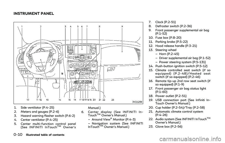
JVC1129X
1. Side ventilator (P.4-25)
2. Meters and gauges (P.2-6)
3. Hazard warning flasher switch (P.6-2)
4. Center ventilator (P.4-25)
5. Center multi-function control panel(See INFINITI InTouch
TMOwner’s Manual.)
6. Center display (See INFINITI In- Touch
TMOwner’s Manual.)
— Around View®Monitor (P.4-3)
— Navigation system (See INFINITI
InTouch
TMOwner’s Manual.) 7. Clock (P.2-51)
8. Defroster switch (P.2-36)
9. Front passenger supplemental air bag
(P.1-52)
10. Fuse box (P.8-20)
11. Parking brake (P.5-22)
12. Hood release handle (P.3-21)
13. Steering wheel — Horn (P.2-45)
— Driver supplemental air bag (P.1-52)
— Power steering system (P.5-131)
14. Push-button ignition switch (P.5-12)
15. Climate controlled seat switch (if so equipped) (P.2-48)/Heated seat
switch (if so equipped) (P.2-46)
16. Remote tip-up 2nd row seat switch (if so equipped) (P.1-9)
17. Front passenger air bag status light (P.1-60)
18. Power outlet (P.2-51)
19. USB connection port (See Infiniti In- Touch Owner’s Manual.)
20. Cup holder (P.2-54)/Tray (P.2-58)
21. Automatic climate control system (P.4-26)
22. Audio system (See INFINITI InTouch
TM
Owner’s Manual.)
23. Glove box (P.2-56)
INSTRUMENT PANEL
Page 94 of 524

Clock ........................................................................\
........... 2-51Adjusting the time ..................................................... 2-51
Power outlet .................................................................... 2-51 USB (Universal Serial Bus)
charging connector ................................................... 2-53
Storage ........................................................................\
...... 2-54 Cup holders ................................................................. 2-54
Sunglasses holder ...................................................... 2-56
Glove box ..................................................................... 2-56
Console box ................................................................ 2-57
Tray ........................................................................\
....... 2-58
Coat hooks .................................................................. 2-59
Luggage hooks .......................................................... 2-59
Cargo floor box ......................................................... 2-60
Roof rack .................................................................... 2-60
Windows ........................................................................\
... 2-61 Power windows ......................................................... 2-61
Moonroof ........................................................................\
.. 2-64
Power moonroof ....................................................... 2-64
Welcome light .................................................................. 2-65 Battery saver system .............................................. 2-66
Interior lights .................................................................... 2-66 Interior light switch .................................................. 2-66
Console light ............................................................... 2-67
Map lights ................................................................... 2-67
Rear personal lights .................................................. 2-68
Vanity mirror lights ........................................................ 2-68 Cargo light ....................................................................... 2-68
HomeLink®Universal Transceiver (Type A) (if
so equipped) .................................................................... 2-69
Programming HomeLink
®..................................... 2-69
Programming HomeLink®for Canadian
customers and gate openers ............................... 2-71
Operating the HomeLink
®
Universal Transceiver ............................................. 2-71
Programming troubleshooting ............................ 2-71
Clearing the programmed information ............. 2-72
Reprogramming a single
HomeLink
®button .................................................. 2-72
If your vehicle is stolen .......................................... 2-72
HomeLink
®Universal Transceiver (Type B) (if
so equipped) .................................................................... 2-73
Programming HomeLink
®..................................... 2-73
Programming HomeLink®for Canadian
customers and gate openers ............................... 2-75
Operating the HomeLink
®
Universal Transceiver ............................................. 2-75
Programming troubleshooting ............................ 2-75
Clearing the programmed information ............. 2-76
Reprogramming a single
HomeLink
®button .................................................. 2-76
Using the garage door
two-way communication ...................................... 2-76
If your vehicle is stolen .......................................... 2-77
Page 97 of 524

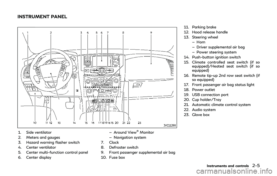
JVC1129X
1. Side ventilator
2. Meters and gauges
3. Hazard warning flasher switch
4. Center ventilator
5. Center multi-function control panel
6. Center display— Around View®Monitor
— Navigation system
7. Clock
8. Defroster switch
9. Front passenger supplemental air bag
10. Fuse box 11. Parking brake
12. Hood release handle
13. Steering wheel
— Horn
— Driver supplemental air bag
— Power steering system
14. Push-button ignition switch
15. Climate controlled seat switch (if so equipped)/Heated seat switch (if so
equipped)
16. Remote tip-up 2nd row seat switch (if so equipped)
17. Front passenger air bag status light
18. Power outlet
19. USB connection port
20. Cup holder/Tray
21. Automatic climate control system
22. Audio system
23. Glove box
Instruments and controls2-5
INSTRUMENT PANEL
Page 128 of 524

2-36Instruments and controls
JVI0972X
REAR WINDOW WIPER AND
WASHER OPERATION
If the rear window wiper operation is
interrupted by snow etc., the wiper may
stop moving to protect its motor. If this
occurs, turn the wiper switch to OFF and
remove the snow etc. on and around the
wiper arms. After about 1 minute, turn the
switch ON again to operate the wiper.
The rear window wiper and washer operate
when the ignition switch is in the ON
position.
Turn the switch clockwise from the OFF
position to operate the wiper.
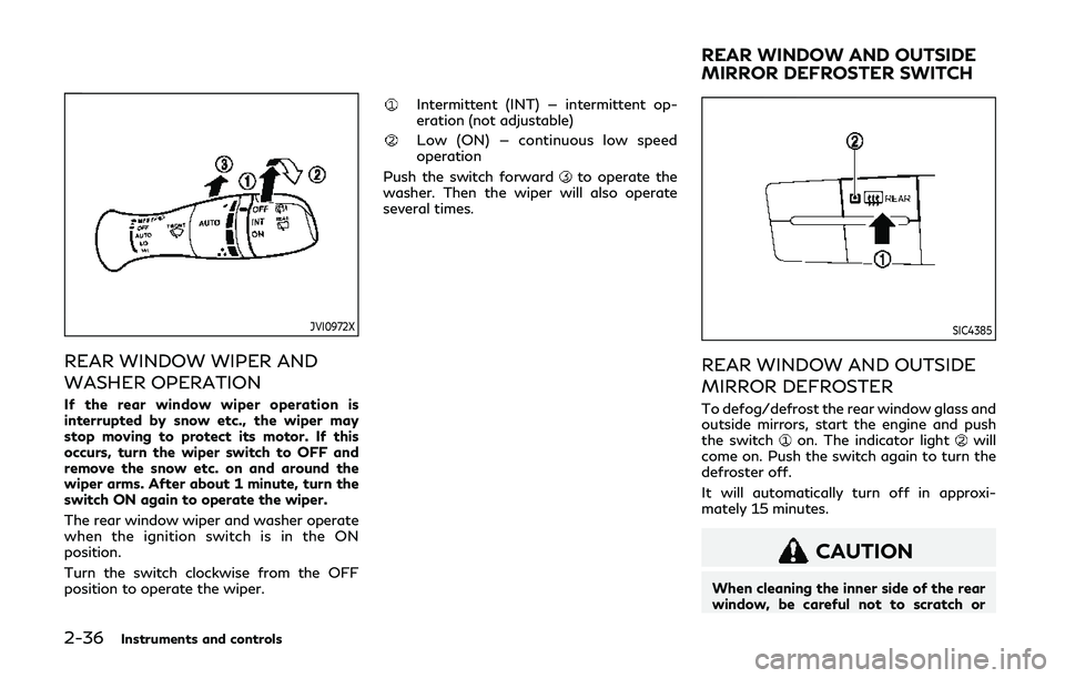
Intermittent (INT) — intermittent op-
eration (not adjustable)
Low (ON) — continuous low speed
operation
Push the switch forward
to operate the
washer. Then the wiper will also operate
several times.
SIC4385
REAR WINDOW AND OUTSIDE
MIRROR DEFROSTER
To defog/defrost the rear window glass and
outside mirrors, start the engine and push
the switch
on. The indicator lightwill
come on. Push the switch again to turn the
defroster off.
It will automatically turn off in approxi-
mately 15 minutes.
CAUTION
When cleaning the inner side of the rear
window, be careful not to scratch or
REAR WINDOW AND OUTSIDE
MIRROR DEFROSTER SWITCH
Page 143 of 524

SIC3325
If the power supply is disconnected, the
clock will not indicate the correct time.
Readjust the time.
ADJUSTING THE TIME
1. To set the clock forward, push thebutton.
2. To set the clock backward, push the button
.
3. To move forward or backward faster, push and hold the button more than 5
seconds.
For details about display clock adjustment,
see the INFINITI InTouch
TMOwner’s Man-
ual.
CAUTION
. Use power outlet with the engine
running to avoid discharging the
vehicle battery.
. Avoid using power outlet when the
air conditioner, headlights or rear
window defroster is on.
. Before inserting or disconnecting a
plug, be sure the electrical accessory
being used is turned OFF.
. When not in use, be sure to close the
cap. Do not allow water or any liquid
to contact the outlet.
SIC4445
Instrument panel
SIC4456
Back side of front console
Instruments and controls2-51
CLOCK POWER OUTLET
Page 198 of 524

3-28Pre-driving checks and adjustments
.Insert the cap straight into the fuel-
filler tube, then tighten until the fuel-
filler cap clicks. Failure to tighten the
fuel-filler cap properly may cause the
malfunction indicator light (MIL)
to illuminate. If thelight illumi-
nates because the fuel-filler cap is
loose or missing, tighten or install the
cap and continue to drive the vehicle.
The
light should turn off after a
few driving trips. If thelight does
not turn off after a few driving trips,
have the vehicle inspected. It is
recommended you visit an INFINITI
retailer for this service.
. The LOOSE FUEL CAP warning will
appear if the fuel-filler cap is not
properly tightened. It may take a few
driving trips for the message to be
displayed. Failure to tighten the fuel-
filler cap properly after the LOOSE
FUEL CAP warning appears may
cause the
Malfunction Indicator
Light (MIL) to illuminate.
Turn the cap counterclockwise to remove.
To tighten, turn the cap clockwise until a
single click is heard.
SPA2753
To remove the fuel-filler cap:
1. Turn the fuel-filler cap counterclockwise to remove.
2. Put the fuel-filler cap on the cap holder
while refueling.
To install the fuel-filler cap:
1. Insert the fuel-filler cap straight into the fuel-filler tube.
2. Turn the fuel-filler cap clockwise until a single click is heard.
SPA2815
LOOSE FUEL CAP warning
The LOOSE FUEL CAP warning appears on
the vehicle information display when the
fuel-filler cap is not tightened correctly after
the vehicle has been refueled. It may take a
few driving trips for the warning to be
displayed.
To turn off the warning, perform the
following:
1. Remove and install the fuel-filler cap assoon as possible. (See “Fuel-filler cap”
(P.3-27).)
2. Tighten the fuel-filler cap until it clicks.
3. Push the
switchon the right side
of the combination meter panel for
Page 394 of 524

6-6In case of emergency
JVE0423X
5. Securely screw to connect the T-shapedend of the jack rod and the extension bar
as illustrated.
6. Fit the square end of the jack rod into the square hole of the wheel nut wrench to
form a handle
. 7. Locate the oval opening above the
middle of the rear bumper.
8. Place the T-shaped end of the jack rod through the opening and direct it to-
wards the spare wheel winch assembly,
located directly above the spare wheel.
SCE0916
CAUTION
Do not insert the jack rod straight as it is
designed to be inserted at an angle as
shown.
9. Seat the T-shaped end of the jack rod into the T-shaped opening of the spare
wheel winch. Apply pressure to keep the
jack rod engaged in the spare wheel
winch and turn the jack rod counter-
clockwise to lower the spare wheel.
Page 397 of 524

SCE0876
2. Loosen each wheel nut one or two turnsby turning counterclockwise with the
wheel nut wrench. Do not remove the
wheel nuts until the tire is off the
ground.
NCE130
3. Install the assembled jack rod into the
jack as shown.
4. Carefully raise the vehicle until the clearance between the tire and ground
is achieved.
5. To lift the vehicle, securely hold the jack lever and rod with both hands and turn
the jack lever.
NOTE:
Before jacking up the vehicle, make sure the
ignition switch is placed in the OFF position.
If the vehicle is lifted up with the engine
running, the auto-leveling suspension will
become disabled after 120 seconds. To
reset the auto-leveling suspension, cycle
In case of emergency6-9
Page 425 of 524

SDI2528
Engine oil and filter
1. Place a large drain pan under the drainplug.
2. Remove the oil filler cap.
3. Remove the drain plug
with a wrench
and completely drain the oil.
CAUTION
Be careful not to burn yourself, as the
engine oil is hot.
.Waste oil must be disposed of prop- erly.
.Check your local regulations.
4. (Perform steps 4 to 7 only when the engine oil filter change is needed.)
Loosen the oil filter
with an oil filter
wrench. Remove the oil filter by turning it
by hand.
5. Wipe the engine oil filter mounting sur- face with a clean rag.
CAUTION
Be sure to remove any old rubber gasket
remaining on the mounting surface of
the engine. Failure to do so could lead to
engine damage.
6. Coat the gasket on the new filter with clean engine oil.
7. Screw in the oil filter clockwise until a slight resistance is felt, then tighten
additionally more than 2/3 turn.
Oil filter tightening torque:11 to 15 ft-lb
(15 to 21 N·m)
8. Clean and re-install the drain plug with a new washer. Securely tighten the drain
plug with a wrench. Drain plug tightening torque:
22 to 29 ft-lb
(29 to 39 N·m)
Do not use excessive force.
9. Refill engine with recommended oil and install the oil filler cap securely.
CAUTION
The dipstick must be inserted in place to
prevent oil spillage from the dipstick
hole while filling the engine with oil.
See “Capacities and recommended
fluids/lubricants” (P.10-2) for drain and
refill capacity. The drain and refill capa-
city depends on the oil temperature and
drain time. Use these specifications for
reference only. Always use the dipstick
to determine the proper amount of oil in
the engine.
10. Start the engine and check for leakage around the drain plug and the oil filter.
Correct as required.
11. Turn the engine off and wait more than 15 minutes. Check the oil level with the
dipstick. Add engine oil if necessary.
Do-it-yourself8-7
Page 495 of 524

JVT0542X
To access the trailer hitch, remove the
trailer hitch cover located on the lower part
of the rear bumper.
To remove the trailer hitch cover:
1. Remove the 2 clips by turning them counterclockwise. 2. Pull the bottom of the cover straight
backward to remove the inner side and
upper clips.
JVT0544X
To install the trailer hitch cover:
1. Insert the upper clips into the recesses
,
and then push the cover to its original
position.
2. Install the 2 clips
by pushing them in as
illustrated.
WARNING
Trailer hitch components have specific
weight ratings. Your vehicle may be
capable of towing a trailer heavier than
the weight rating of the hitch compo-
nents. Never exceed the weight rating of
the hitch components. Doing so can
Technical and consumer information10-23