brake pads ISUZU AXIOM 2002 Service User Guide
[x] Cancel search | Manufacturer: ISUZU, Model Year: 2002, Model line: AXIOM, Model: ISUZU AXIOM 2002Pages: 2100, PDF Size: 19.35 MB
Page 682 of 2100

5C±2
POWER±ASSISTED BRAKE SYSTEM
Inspection and Repair 5C±40. . . . . . . . . . . . . . . . . .
Reassembly 5C±40. . . . . . . . . . . . . . . . . . . . . . . . . .
Main Data and Specifications 5C±42. . . . . . . . . . .
Rear Disc Brake Pads (4y4 Model) 5C±43. . . . . . . .
Brake Pads Inspection 5C±43. . . . . . . . . . . . . . . . .
Brake Pads and Associated Parts 5C±43. . . . . . .
Removal 5C±44. . . . . . . . . . . . . . . . . . . . . . . . . . . . .
Installation 5C±44. . . . . . . . . . . . . . . . . . . . . . . . . . . .
Rear Disc Brake Rotor (4y4 Model) 5C±46. . . . . . . .
Inspection 5C±46. . . . . . . . . . . . . . . . . . . . . . . . . . . .
Replacing Brake Rotors 5C±46. . . . . . . . . . . . . . . .
Refinishing Brake Rotors 5C±46. . . . . . . . . . . . . . .
Rear Drum (In Disc) Inside Diameter Check 5C±47
Rear Disc Brake Caliper Assembly
(4y4 Model) 5C±48. . . . . . . . . . . . . . . . . . . . . . . . . . . .
Rear Disc Brake Caliper Assembly and
Associated Parts 5C±48. . . . . . . . . . . . . . . . . . . . . .
Removal 5C±48. . . . . . . . . . . . . . . . . . . . . . . . . . . . .
Installation 5C±49. . . . . . . . . . . . . . . . . . . . . . . . . . . .
Rear Disc Brake Caliper (4y4 Model) 5C±50. . . . . .
Rear Disc Brake Caliper Disassembled
View 5C±50. . . . . . . . . . . . . . . . . . . . . . . . . . . . . . . . Disassembly 5C±51. . . . . . . . . . . . . . . . . . . . . . . . . .
Inspection and Repair 5C±51. . . . . . . . . . . . . . . . . .
Reassembly 5C±51. . . . . . . . . . . . . . . . . . . . . . . . . .
Main Data and Specifications (4y4 Model) 5C±53
Brake Lining 5C±54. . . . . . . . . . . . . . . . . . . . . . . . . . . .
Brake Lining and Associated Parts 5C±54. . . . . . .
Removal 5C±54. . . . . . . . . . . . . . . . . . . . . . . . . . . . .
Brake Lining Inspection 5C±55. . . . . . . . . . . . . . . .
Installation 5C±55. . . . . . . . . . . . . . . . . . . . . . . . . . . .
Drum Brake Adjustment (4y2 Model) 5C±56. . . . .
Servicing The Brake Drum 5C±56. . . . . . . . . . . . . .
Wheel Cylinder Assembly (4y2 Model) 5C±57. . . . .
Wheel Cylinder Assembly and Associated
Parts 5C±57. . . . . . . . . . . . . . . . . . . . . . . . . . . . . . . .
Removal 5C±57. . . . . . . . . . . . . . . . . . . . . . . . . . . . .
Installation 5C±57. . . . . . . . . . . . . . . . . . . . . . . . . . . .
Disassembled View 5C±58. . . . . . . . . . . . . . . . . . . .
Disassembly 5C±58. . . . . . . . . . . . . . . . . . . . . . . . . .
Inspection and Repair 5C±58. . . . . . . . . . . . . . . . . .
Reassembly 5C±58. . . . . . . . . . . . . . . . . . . . . . . . . .
Main Data and Specifications 5C±60. . . . . . . . . . .
Service Precaution
WARNING: THIS VEHICLE HAS A SUPPLEMENTAL
RESTRAINT SYSTEM (SRS). REFER TO THE SRS
COMPONENT AND WIRING LOCATION VIEW IN
ORDER TO DETERMINE WHETHER YOU ARE
PERFORMING SERVICE ON OR NEAR THE SRS
COMPONENTS OR THE SRS WIRING. WHEN YOU
ARE PERFORMING SERVICE ON OR NEAR THE SRS
COMPONENTS OR THE SRS WIRING, REFER TO
THE SRS SERVICE INFORMATION. FAILURE TO
FOLLOW WARNINGS COULD RESULT IN POSSIBLE
AIR BAG DEPLOYMENT, PERSONAL INJURY, OR
OTHERWISE UNNEEDED SRS SYSTEM REPAIRS.
CAUTION: Always use the correct fastener in the
proper location. When you replace a fastener, use
ONLY the exact part number for that application.
ISUZU will call out those fasteners that require a
replacement after removal. ISUZU will also call out
the fasteners that require thread lockers or thread
sealant. UNLESS OTHERWISE SPECIFIED, do not
use supplemental coatings (Paints, greases, or other
corrosion inhibitors) on threaded fasteners or
fastener joint interfaces. Generally, such coatings
adversely affect the fastener torque and the joint
clamping force, and may damage the fastener. When
you install fasteners, use the correct tightening
sequence and specifications. Following these
instructions can help you avoid damage to parts and
systems.
General Description
Master Cylinder Assembly
330RS001
Page 684 of 2100
5C±4
POWER±ASSISTED BRAKE SYSTEM
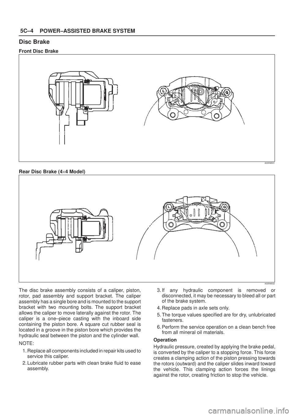
Disc Brake
Front Disc Brake
A05RW001
Rear Disc Brake (4y4 Model)
A05RW002
The disc brake assembly consists of a caliper, piston,
rotor, pad assembly and support bracket. The caliper
assembly has a single bore and is mounted to the support
bracket with two mounting bolts. The support bracket
allows the caliper to move laterally against the rotor. The
caliper is a one±piece casting with the inboard side
containing the piston bore. A square cut rubber seal is
located in a groove in the piston bore which provides the
hydraulic seal between the piston and the cylinder wall.
NOTE:
1. Replace all components included in repair kits used to
service this caliper.
2. Lubricate rubber parts with clean brake fluid to ease
assembly.3. If any hydraulic component is removed or
disconnected, it may be necessary to bleed all or part
of the brake system.
4. Replace pads in axle sets only.
5. The torque values specified are for dry, unlubricated
fasteners.
6. Perform the service operation on a clean bench free
from all mineral oil materials.
Operation
Hydraulic pressure, created by applying the brake pedal,
is converted by the caliper to a stopping force. This force
creates a clamping action of the piston pressing towards
the rotors (outward) and the caliper slides inward toward
the vehicle. This clamping action forces the linings
against the rotor, creating friction to stop the vehicle.
Page 687 of 2100
5C±7 POWER±ASSISTED BRAKE SYSTEM
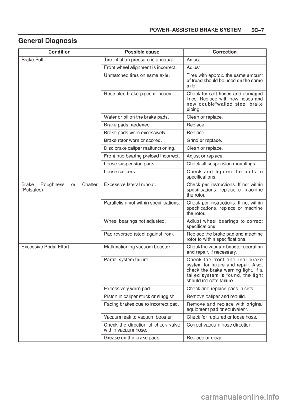
General Diagnosis
ConditionPossible causeCorrection
Brake PullTire inflation pressure is unequal.Adjust
Front wheel alignment is incorrect.Adjust
Unmatched tires on same axle.Tires with approx. the same amount
of tread should be used on the same
axle.
Restricted brake pipes or hoses.Check for soft hoses and damaged
lines. Replace with new hoses and
new doubleªwalled steel brake
piping.
Water or oil on the brake pads.Clean or replace.
Brake pads hardened.Replace
Brake pads worn excessively.Replace
Brake rotor worn or scored.Grind or replace.
Disc brake caliper malfunctioning.Clean or replace.
Front hub bearing preload incorrect.Adjust or replace.
Loose suspension parts.Check all suspension mountings.
Loose calipers.Check and tighten the bolts to
specifications.
Brake Roughness or Chatter
(Pulsates)Excessive lateral runout.Check per instructions. If not within
specifications, replace or machine
the rotor.
Parallelism not within specifications.Check per instructions. If not within
specifications, replace or machine
the rotor.
Wheel bearings not adjusted.Adjust wheel bearings to correct
specifications
Pad reversed (steel against iron).Replace the brake pad and machine
rotor to within specifications.
Excessive Pedal EffortMalfunctioning vacuum booster.Check the vacuum booster operation
and repair, if necessary.
Partial system failure.Check the front and rear brake
system for failure and repair. Also,
check the brake warning light. If a
failed system is found, the light
should indicate failure.
Excessively worn pad.Check and replace pads in sets.
Piston in caliper stuck or sluggish.Remove caliper and rebuild.
Fading brakes due to incorrect pad.Remove and replace with original
equipment pad or equivalent.
Vacuum leak to vacuum booster.Check for ruptured or loose hose.
Check the direction of check valve
within vacuum hose.Correct vacuum hose direction.
Grease on the brake pads.Replace or clean.
Page 688 of 2100

5C±8
POWER±ASSISTED BRAKE SYSTEM
Condition CorrectionPossible cause
Excessive Brake Pedal TravelAir in hydraulic circuit.Bleed the hydraulic circuit.
Level of brake fluid in the reservoir
too low.Replenish brake fluid reservoir to
specified level and bleed hydraulic
circuit as necessary.
Master cylinder push rod clearance
excessive.Adjust
Leakage in hydraulic system.Correct or replace defective parts.
Brake DragMaster cylinder pistons not returning
correctly.Adjust the stop light switch and
vacuum booster push rod. If
necessary, rebuild.
Restricted brake pipes or hoses.Check for soft hoses or damaged
pipes, and replace with new hoses
and new double±walled steel brake
piping.
Parking brake maladjusted.Adjust
Parking brake lining clearance
insufficient.Adjust
Brake pedal free play insufficient.Adjust the brake pedal height or
power cylinder operating rod.
Piston in the master cylinder sticking.Replace
Piston in the disc brake caliper
sticking.Replace piston seals.
Brake pads sticking in caliper.Clean
Return spring weakened.Replace
Parking brake binding.Overhaul the parking brakes and
correct.
Front hub bearing preload incorrect.Adjust or replace.
Parking brake shoes not returning.Correct or replace the brake back
plate and brake shoe as necessary.
Obstructions in hydraulic circuit.Clean
Rotor warped excessively.Grind or replace.
Rear brake drum distorted.Grind or replace.
Parking cable sticking.Grind or replace.
Grabbing or Uneven Braking Action
(All conditions listed under ªPullsº)Malfunctioning vacuum booster.Check operation and correct as
necessary.
Binding brake pedal mechanism.Check and lubricate, if necessary.
Corroded caliper assembly.Clean and lubricate.
Brake NoisyBrake pads are worn.Replace
Brake pads are hardened.Replace
Brake pads are in poor contact with
rotor.Correct
Brake disc(s) warped, worn or
damaged.Grind or replace.
Disc brake anti±squeak shims
fatigued.Replace
Front hub bearings are loose or
preload is incorrect.Adjust or replace.
Brake disc is rusted.Grind or replace.
Page 689 of 2100

5C±9 POWER±ASSISTED BRAKE SYSTEM
Condition CorrectionPossible cause
Poor Brake ActionMaster cylinder faulty.Correct or replace.
Vacuum booster faulty.Correct or replace.
Level of brake fluid in reservoir too
low.Replenish and bleed.
Air in hydraulic circuit.Bleed
Disc brake caliper faulty.Clean or replace.
Water or oil on brake pads.Clean or replace.
Brake pads in poor contact with the
rotor.Correct
Brake pads worn.Replace
Brake disc rusted.Grind or replace.
Check valve in vacuum hose faulty.Correct or replace.
Page 712 of 2100
5C±32
POWER±ASSISTED BRAKE SYSTEM
Front Disc Brake Pads
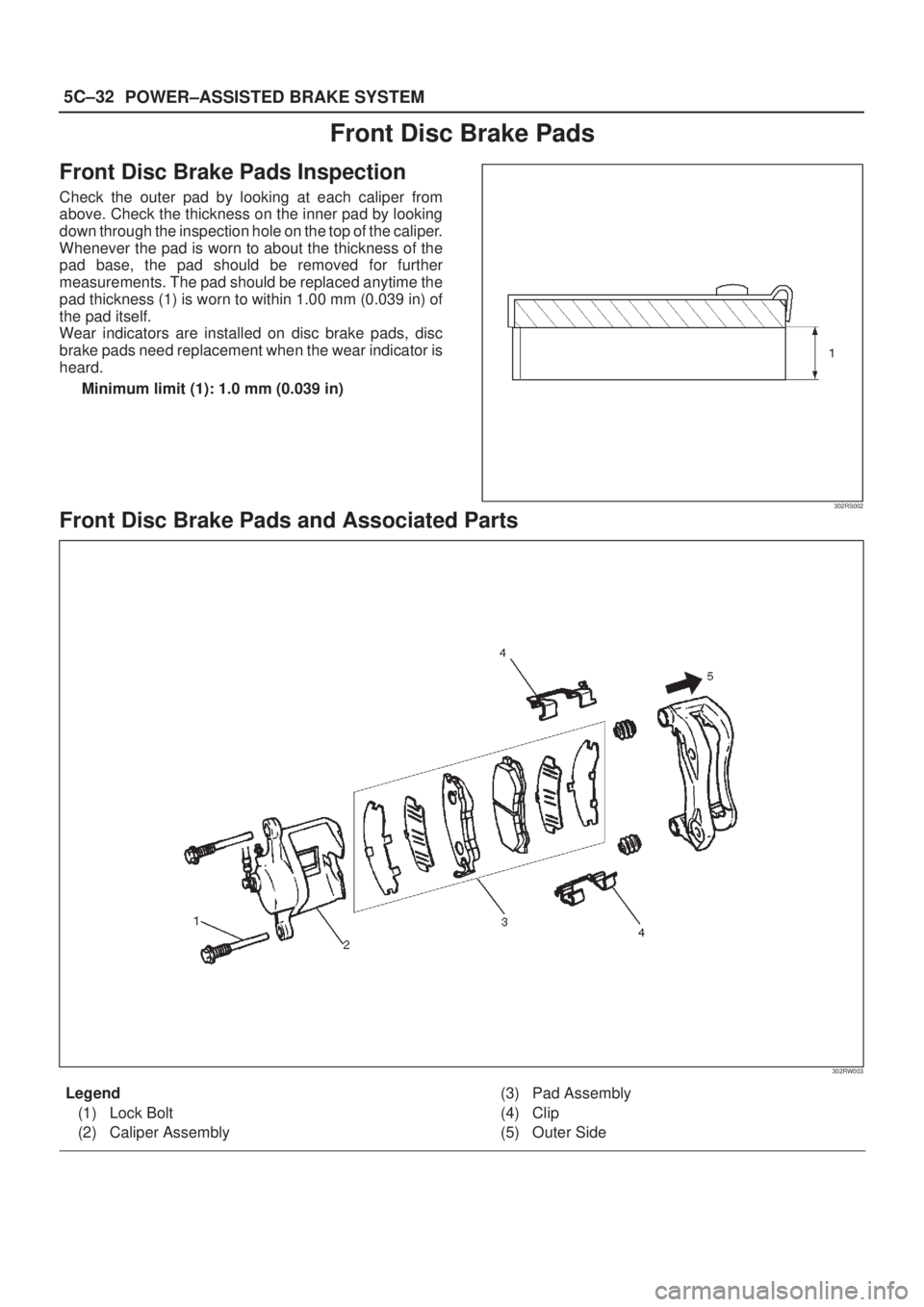
Front Disc Brake Pads Inspection
Check the outer pad by looking at each caliper from
above. Check the thickness on the inner pad by looking
down through the inspection hole on the top of the caliper.
Whenever the pad is worn to about the thickness of the
pad base, the pad should be removed for further
measurements. The pad should be replaced anytime the
pad thickness (1) is worn to within 1.00 mm (0.039 in) of
the pad itself.
Wear indicators are installed on disc brake pads, disc
brake pads need replacement when the wear indicator is
heard.
Minimum limit (1): 1.0 mm (0.039 in)
302RS002
Front Disc Brake Pads and Associated Parts
302RW003
Legend
(1) Lock Bolt
(2) Caliper Assembly(3) Pad Assembly
(4) Clip
(5) Outer Side
Page 723 of 2100

5C±43 POWER±ASSISTED BRAKE SYSTEM
Rear Disc Brake Pads (4y4 Model)
Brake Pads Inspection
Check the outer pads by looking at each caliper from
above. Check the thickness on the inner pad by looking
down through the inspection hole in the top of the caliper.
Whenever the pad is worn to about the thickness of the
pad base, the pad should be removed for further
measurements. The pad should be replaced anytime the
pad thickness (1) is worn to within 1.0 mm (0.039 in) of the
pad itself.
Wear indicators are installed on disc brake pads, disc
brake pads need replacement when the wear indicator is
heard.
Minimum limit (1): 1.0 mm (0.039 in)
302RW016
Brake Pads and Associated Parts
306RW001
Legend
(1) Caliper Assembly
(2) Clip(3) Lock Bolt
(4) Pad Assembly
Page 741 of 2100

5C±61 POWER±ASSISTED BRAKE SYSTEM
AXIOM (Vehicles Produced After Aug./1/2001)
POWER-ASSISTED BRAKE SYSTEM
CONTENTS
Service Precaution 5C±62. . . . . . . . . . . . . . . . . . . . . .
General Description 5C±62. . . . . . . . . . . . . . . . . . . . .
Diagnosis 5C±66. . . . . . . . . . . . . . . . . . . . . . . . . . . . . .
General Diagnosis 5C±67. . . . . . . . . . . . . . . . . . . . . . .
Hydraulic Brakes 5C±70. . . . . . . . . . . . . . . . . . . . . . . .
Filling Master Cylinder Reservoir 5C±70. . . . . . . .
Deterioration of Brake Fluid 5C±70. . . . . . . . . . . . .
Leakage of Brake Fluid 5C±70. . . . . . . . . . . . . . . . .
Bleeding Brake Hydraulic System 5C±70. . . . . . . .
Flushing Brake Hydraulic System 5C±71. . . . . . . .
Brake Pipes and Hoses 5C±71. . . . . . . . . . . . . . . .
Brake Hose Inspection 5C±71. . . . . . . . . . . . . . . . .
Front Caliper Brake Hose 5C±72. . . . . . . . . . . . . . . .
Front Caliper Brake Hose and Associated
Parts 5C±72. . . . . . . . . . . . . . . . . . . . . . . . . . . . . . . .
Removal 5C±72. . . . . . . . . . . . . . . . . . . . . . . . . . . . .
Installation 5C±72. . . . . . . . . . . . . . . . . . . . . . . . . . . .
Rear Axle Brake Hose 5C±73. . . . . . . . . . . . . . . . . . .
Rear Axle Brake Hose and Associated
Parts 5C±73. . . . . . . . . . . . . . . . . . . . . . . . . . . . . . . .
Removal 5C±73. . . . . . . . . . . . . . . . . . . . . . . . . . . . .
Installation 5C±73. . . . . . . . . . . . . . . . . . . . . . . . . . . .
Brake Pipe 5C±74. . . . . . . . . . . . . . . . . . . . . . . . . . . . .
Removal 5C±74. . . . . . . . . . . . . . . . . . . . . . . . . . . . .
Installation 5C±74. . . . . . . . . . . . . . . . . . . . . . . . . . . .
P & B (Proportioning and Bypass) Valve 5C±75. . . .
Removal 5C±75. . . . . . . . . . . . . . . . . . . . . . . . . . . . .
Installation 5C±75. . . . . . . . . . . . . . . . . . . . . . . . . . . .
Main Data and Specifications 5C±76. . . . . . . . . . . . .
Brake Pedal 5C±77. . . . . . . . . . . . . . . . . . . . . . . . . . . .
Checking Pedal Height 5C±77. . . . . . . . . . . . . . . . .
Checking Pedal Travel 5C±77. . . . . . . . . . . . . . . . .
Brake Pedal and Associated Parts 5C±78. . . . . . .
Removal 5C±78. . . . . . . . . . . . . . . . . . . . . . . . . . . . .
Installation 5C±78. . . . . . . . . . . . . . . . . . . . . . . . . . . .
Stoplight Switch 5C±79. . . . . . . . . . . . . . . . . . . . . . . . .
Parts Location 5C±79. . . . . . . . . . . . . . . . . . . . . . . .
Removal 5C±79. . . . . . . . . . . . . . . . . . . . . . . . . . . . .
Installation 5C±79. . . . . . . . . . . . . . . . . . . . . . . . . . . .
Main Data and Specifications 5C±80. . . . . . . . . . . . .
Master Cylinder Assembly 5C±81. . . . . . . . . . . . . . . .
Master Cylinder Assembly and Associated
Parts 5C±81. . . . . . . . . . . . . . . . . . . . . . . . . . . . . . . .
Removal 5C±81. . . . . . . . . . . . . . . . . . . . . . . . . . . . .
Inspection 5C±81. . . . . . . . . . . . . . . . . . . . . . . . . . . . Master Cylinder Assembly 5C±82. . . . . . . . . . . . . . . .
Master Cylinder Assembly Desassembled
View 5C±82. . . . . . . . . . . . . . . . . . . . . . . . . . . . . . . .
Desassembly 5C±82. . . . . . . . . . . . . . . . . . . . . . . . .
Inspection 5C±82. . . . . . . . . . . . . . . . . . . . . . . . . . . .
Reassembly 5C±83. . . . . . . . . . . . . . . . . . . . . . . . . .
Installation 5C±83. . . . . . . . . . . . . . . . . . . . . . . . . . . .
Main Data and Specifications 5C±84. . . . . . . . . . .
Vacuum Booster Assembly 5C±85. . . . . . . . . . . . . . .
Vacuum Booster Assembly and Associated
Parts 5C±85. . . . . . . . . . . . . . . . . . . . . . . . . . . . . . . .
Removal 5C±85. . . . . . . . . . . . . . . . . . . . . . . . . . . . .
Inspection and Repair 5C±86. . . . . . . . . . . . . . . . . .
Exterior Components 5C±87. . . . . . . . . . . . . . . . . . . .
Exterior Components and Associated
Parts 5C±87. . . . . . . . . . . . . . . . . . . . . . . . . . . . . . . .
Removal 5C±87. . . . . . . . . . . . . . . . . . . . . . . . . . . . .
Inspection and Repair 5C±88. . . . . . . . . . . . . . . . . .
Installation 5C±88. . . . . . . . . . . . . . . . . . . . . . . . . . . .
Vacuum Booster Overhaul 5C±88. . . . . . . . . . . . . . . .
Vacuum Booster 5C±88. . . . . . . . . . . . . . . . . . . . . . .
Main Data and Specifications 5C±89. . . . . . . . . . . . .
Front Disc Brake Pads 5C±90. . . . . . . . . . . . . . . . . . .
Front Disc Brake Pads Inspection 5C±90. . . . . . . .
Front Disc Brake Pads and Associated
Parts 5C±90. . . . . . . . . . . . . . . . . . . . . . . . . . . . . . . .
Removal 5C±91. . . . . . . . . . . . . . . . . . . . . . . . . . . . .
Installation 5C±91. . . . . . . . . . . . . . . . . . . . . . . . . . . .
Front Disc Brake Rotor 5C±93. . . . . . . . . . . . . . . . . . .
Inspection 5C±93. . . . . . . . . . . . . . . . . . . . . . . . . . . .
Replacing Brake Rotors 5C±93. . . . . . . . . . . . . . . .
Refinishing Brake Rotors 5C±93. . . . . . . . . . . . . . .
Front Disc Brake Caliper Assembly 5C±95. . . . . . . .
Front Disc Brake Caliper Assembly and
Associated Parts 5C±95. . . . . . . . . . . . . . . . . . . . . .
Removal 5C±95. . . . . . . . . . . . . . . . . . . . . . . . . . . . .
Installation 5C±96. . . . . . . . . . . . . . . . . . . . . . . . . . . .
Front Disc Brake Caliper 5C±98. . . . . . . . . . . . . . . . .
Front Disc Brake Caliper Disassembled
View 5C±98. . . . . . . . . . . . . . . . . . . . . . . . . . . . . . . .
Disassembly 5C±98. . . . . . . . . . . . . . . . . . . . . . . . . .
Inspection and Repair 5C±99. . . . . . . . . . . . . . . . . .
Reassembly 5C±99. . . . . . . . . . . . . . . . . . . . . . . . . .
Main Data and Specifications 5C±100. . . . . . . . . . .
Rear Disc Brake Pads (4y4 Model) 5C±101. . . . . . . .
Page 742 of 2100

5C±62
POWER±ASSISTED BRAKE SYSTEM
Brake Pads Inspection 5C±101. . . . . . . . . . . . . . . . .
Brake Pads and Associated Parts 5C±101. . . . . . .
Removal 5C±102. . . . . . . . . . . . . . . . . . . . . . . . . . . . .
Installation 5C±102. . . . . . . . . . . . . . . . . . . . . . . . . . . .
Rear Disc Brake Rotor (4y4 Model) 5C±104. . . . . . . .
Inspection 5C±104. . . . . . . . . . . . . . . . . . . . . . . . . . . .
Replacing Brake Rotors 5C±104. . . . . . . . . . . . . . . .
Refinishing Brake Rotors 5C±104. . . . . . . . . . . . . . .
Rear Drum (In Disc) Inside Diameter
Check 5C±105. . . . . . . . . . . . . . . . . . . . . . . . . . . . . . .
Rear Disc Brake Caliper Assembly
(4y4 Model) 5C±106. . . . . . . . . . . . . . . . . . . . . . . . . . . .
Rear Disc Brake Caliper Assembly and
Associated Parts 5C±106. . . . . . . . . . . . . . . . . . . . . .
Removal 5C±106. . . . . . . . . . . . . . . . . . . . . . . . . . . . .
Installation 5C±107. . . . . . . . . . . . . . . . . . . . . . . . . . . .
Rear Disc Brake Caliper (4y4 Model) 5C±108. . . . . .
Rear Disc Brake Caliper Disassembled
View 5C±108. . . . . . . . . . . . . . . . . . . . . . . . . . . . . . . .
Disassembly 5C±109. . . . . . . . . . . . . . . . . . . . . . . . . .
Inspection and Repair 5C±109. . . . . . . . . . . . . . . . . . Reassembly 5C±109. . . . . . . . . . . . . . . . . . . . . . . . . .
Main Data and Specifications
(4y4 Model) 5C±111. . . . . . . . . . . . . . . . . . . . . . . . . .
Brake Lining 5C±112. . . . . . . . . . . . . . . . . . . . . . . . . . . .
Brake Lining and Associated Parts 5C±112. . . . . . .
Removal 5C±112. . . . . . . . . . . . . . . . . . . . . . . . . . . . .
Brake Lining Inspection 5C±113. . . . . . . . . . . . . . . .
Installation 5C±113. . . . . . . . . . . . . . . . . . . . . . . . . . . .
Drum Brake Adjustment (4y2 Model) 5C±114. . . . .
Servicing The Brake Drum 5C±114. . . . . . . . . . . . . .
Wheel Cylinder Assembly (4y2 Model) 5C±115. . . . .
Wheel Cylinder Assembly and Associated
Parts 5C±115. . . . . . . . . . . . . . . . . . . . . . . . . . . . . . . .
Removal 5C±115. . . . . . . . . . . . . . . . . . . . . . . . . . . . .
Installation 5C±115. . . . . . . . . . . . . . . . . . . . . . . . . . . .
Disassembled View 5C±116. . . . . . . . . . . . . . . . . . . .
Disassembly 5C±116. . . . . . . . . . . . . . . . . . . . . . . . . .
Inspection and Repair 5C±116. . . . . . . . . . . . . . . . . .
Reassembly 5C±116. . . . . . . . . . . . . . . . . . . . . . . . . .
Main Data and Specifications 5C±118. . . . . . . . . . . . .
Service Precaution
WARNING: THIS VEHICLE HAS A SUPPLEMENTAL
RESTRAINT SYSTEM (SRS). REFER TO THE
SRS
COMPONENT AND WIRING LOCATION VIEW
IN
ORDER TO DETERMINE WHETHER YOU ARE
PERFORMING SERVICE ON OR NEAR THE SRS
COMPONENTS OR THE SRS WIRING. WHEN YOU
ARE PERFORMING SERVICE ON OR NEAR THE SRS
COMPONENTS OR THE SRS WIRING, REFER TO
THE
SRS SERVICE INFORMATION. FAILURE TO
FOLLOW WARNINGS COULD RESULT IN POSSIBLE
AIR BAG DEPLOYMENT, PERSONAL INJURY, OR
OTHERWISE UNNEEDED SRS SYSTEM REPAIRS.
CAUTION: Always use the correct fastener in the
proper location. When you replace a fastener, use
ONLY the exact part number for that application.
ISUZU will call out those fasteners that require a
replacement after removal. ISUZU will also call out
the fasteners that require thread lockers or thread
sealant. UNLESS OTHERWISE SPECIFIED, do not
use supplemental coatings (Paints, greases, or other
corrosion inhibitors) on threaded fasteners or
fastener joint interfaces. Generally, such coatings
adversely affect the fastener torque and the joint
clamping force, and may damage the fastener. When
you install fasteners, use the correct tightening
sequence and specifications. Following these
instructions can help you avoid damage to parts and
systems.
General Description
Master Cylinder Assembly
330R200002
Page 744 of 2100

5C±64
POWER±ASSISTED BRAKE SYSTEM
Disc Brake
Front Disc Brake
A05R200001
Rear Disc Brake (4y4 Model)
A05RW002
The disc brake assembly consists of a caliper, piston,
rotor, pad assembly and support bracket. The caliper
assembly has a fornt dual bore, rear single bore and is
mounted to the support bracket with two mounting bolts.
The support bracket allows the caliper to move laterally
against the rotor. The caliper is a one±piece casting with
the inboard side containing the piston bore. A square cut
rubber seal is located in a groove in the piston bore which
provides the hydraulic seal between the piston and the
cylinder wall.
NOTE:
1. Replace all components included in repair kits used to
service this caliper.
2. Lubricate rubber parts with clean brake fluid to ease
assembly.3. If any hydraulic component is removed or
disconnected, it may be necessary to bleed all or part
of the brake system.
4. Replace pads in axle sets only.
5. The torque values specified are for dry, unlubricated
fasteners.
6. Perform the service operation on a clean bench free
from all mineral oil materials.
Operation
Hydraulic pressure, created by applying the brake pedal,
is converted by the caliper to a stopping force. This force
creates a clamping action of the piston pressing towards
the rotors (outward) and the caliper slides inward toward
the vehicle. This clamping action forces the linings
against the rotor, creating friction to stop the vehicle.