AUX ISUZU AXIOM 2002 Service Repair Manual
[x] Cancel search | Manufacturer: ISUZU, Model Year: 2002, Model line: AXIOM, Model: ISUZU AXIOM 2002Pages: 2100, PDF Size: 19.35 MB
Page 21 of 2100

0B±7 MAINTENANCE AND LUBRICATION
Automatic Transmission Fluid
Replacement
Under harsh operating conditions, such as constant
driving in heavy city traffic during hot weather, or in hilly or
mountainous terrain, change the transmission fluid and
service the sump filter after every 20,000 miles (32,000
km) of operation.
More over, the remaining life percentage of ATF can be
estimated by using TECH±II as an auxiliary tool to judge
the right time for ATF replacement.
The remaining life percentage is calculated from ATF'S
heat history. When it is close to 0%, ATF replacement is
recommended.
Auto Cruise Control Inspection
Check to see if the clearance between cruise link and
accelerator link is normal. Also check that the connected
properly.
Accelerator Linkage Inspection
Inspect for interference, binding, and damaged or
missing parts. Check accelerator pedal for smooth
operation and even pedal effort. Replace parts as
needed.
Page 385 of 2100

DRIVE LINE CONTROL SYSTEM (TOD) 4B2±6
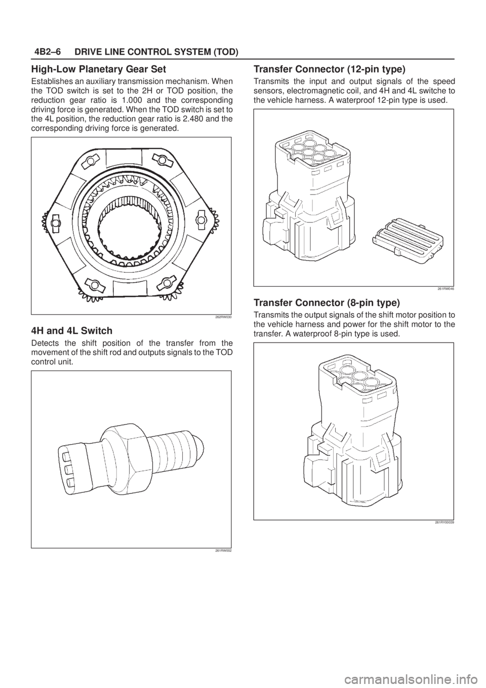
High-Low Planetary Gear Set
Establishes an auxiliary transmission mechanism. When
the TOD switch is set to the 2H or TOD position, the
reduction gear ratio is 1.000 and the corresponding
driving force is generated. When the TOD switch is set to
the 4L position, the reduction gear ratio is 2.480 and the
corresponding driving force is generated.
262RW030
4H and 4L Switch
Detects the shift position of the transfer from the
movement of the shift rod and outputs signals to the TOD
control unit.
261RW002
Transfer Connector (12-pin type)
Transmits the input and output signals of the speed
sensors, electromagnetic coil, and 4H and 4L switche to
the vehicle harness. A waterproof 12-pin type is used.
261RW046
Transfer Connector (8-pin type)
Transmits the output signals of the shift motor position to
the vehicle harness and power for the shift motor to the
transfer. A waterproof 8-pin type is used.
261RY00039
Page 933 of 2100

ENGINE ELECTRICAL (6VE1 3.5L)6D1±3
Battery Charging
Observe the following safety precautions when charging
the battery:
1. Never attempt to charge the battery when the fluid
level is below the lower level line on the side of the
battery. In this case, the battery must be replaced.
2. Pay close attention to the battery during charging
procedure.
Battery charging should be discontinued or the rate of
charge reduced if the battery feels hot to the touch.
Battery charging should be discontinued or the rate of
charge reduced if the battery begins to gas or spew
electrolyte from the vent holes.
3. In order to more easily view the hydrometer blue dot
or ring, it may be necessary to jiggle or tilt the battery.
4. Battery temperature can have a great effect on
battery charging capacity.
5. The sealed battery used on this vehicle may be either
quick charged or slow charged in the same manner as
other batteries.
Whichever method you decide to use, be sure that
you completely charge the battery. Never partially
charge the battery.
Jump Starting
Jump Starting with an Auxiliary (Booster)
Battery
CAUTION: Never push or tow the vehicle in an
attempt to start it. Serious damage to the emission
system as well as other vehicle parts will result.
Treat both the discharged battery and the booster
battery with great care when using jumper cables.
Carefully follow the jump starting procedure, being
careful at all times to avoid sparking.
WARNING: FAILURE TO CAREFULLY FOLLOW THE
JUMP STARTING PROCEDURE COULD RESULT IN
THE FOLLOWING:
1. Serous personal injury, particularly to your eyes.
2. Property damage from a battery explosion, battery
acid, or an electrical fire.
3. Damage to the electronic components of one or both
vehicles particularly.
Never expose the battery to an open flame or electrical
spark. Gas generated by the battery may catch fire or
explode.
Remove any rings, watches, or other jewelry before
working around the battery. Protect your eyes by wearing
an approved set of goggles.
Never allow battery fluid to come in contact with your eyes
or skin.Never allow battery fluid to come in contact with fabrics or
painted surfaces.
Battery fluid is a highly corrosive acid.
Should battery fluid come in contact with your eyes, skin,
fabric, or a painted surface, immediately and thoroughly
rinse the affected area with clean tap water.
Never allow metal tools or jumper cables to come in
contact with the positive battery terminal, or any other
metal surface of the vehicle. This will protect against a
short circuit.
Always keep batteries out of reach of young children.
Jump Starting Procedure
1. Set the vehicle parking brake.
If the vehicle is equipped with an automatic
transmission, place the selector level in the ªPARKº
position.
If the vehicle is equipped with a manual transmission,
place the shift lever in the ªNEUTRALº position.
Turn ªOFFº the ignition.
Turn ªOFFº all lights and any other accessory
requiring electrical power.
2. Look at the built±in hydrometer.
If the indication area of the built±in hydrometer is
completely clear, do not try to jump start.
3. Attach the end of one jumper cable to the positive
terminal of the booster battery.
Attach the other end of the same cable to the positive
terminal of the discharged battery.
Do not allow the vehicles to touch each other. This will
cause a ground connection, effectively neutralizing
the charging procedure.
Be sure that the booster battery has a 12 volt rating.
4. Attach one end of the remaining cable to the negative
terminal of the booster battery.
Attach the other end of the same cable to a solid
engine ground (such as the air conditioning
compressor bracket or the generator mounting
bracket) of the vehicle with the discharged battery.
The ground connection must be at least 450 mm (18
in.) from the battery of the vehicle whose battery is
being charged.
WARNING: NEVER ATTACH THE END OF THE
JUMPER CABLE DIRECTLY TO THE NEGATIVE
TERMINAL OF THE DEAD BATTERY.
5. Start the engine of the vehicle with the good battery.
Make sure that all unnecessary electrical accessories
have been turned ªOFFº.
6. Start the engine of the vehicle with the dead battery.
Page 1587 of 2100

7A±3 AUTOMATIC TRANSMISSION (4L30±E)
Construction
A07R100002
Legend
(1) Torque Converter Clutch (TCC)
(2) Overdrive Free Wheel (One Way Clutch)
(OFW)
(3) Fourth Clutch (C4)
(4) Overrun Clutch (OC)
(5) Overdrive Unit(6) Reverse Clutch (RC)
(7) Second Clutch (C2)
(8) Third Clutch (C3)
(9) Principle Sprag Assembly (One Way Clutch)
(PFW)
(10) Ravigneaux Planetary Gear Set
(11) Brake Band (B)
Page 1673 of 2100

7A±89 AUTOMATIC TRANSMISSION (4L30±E)
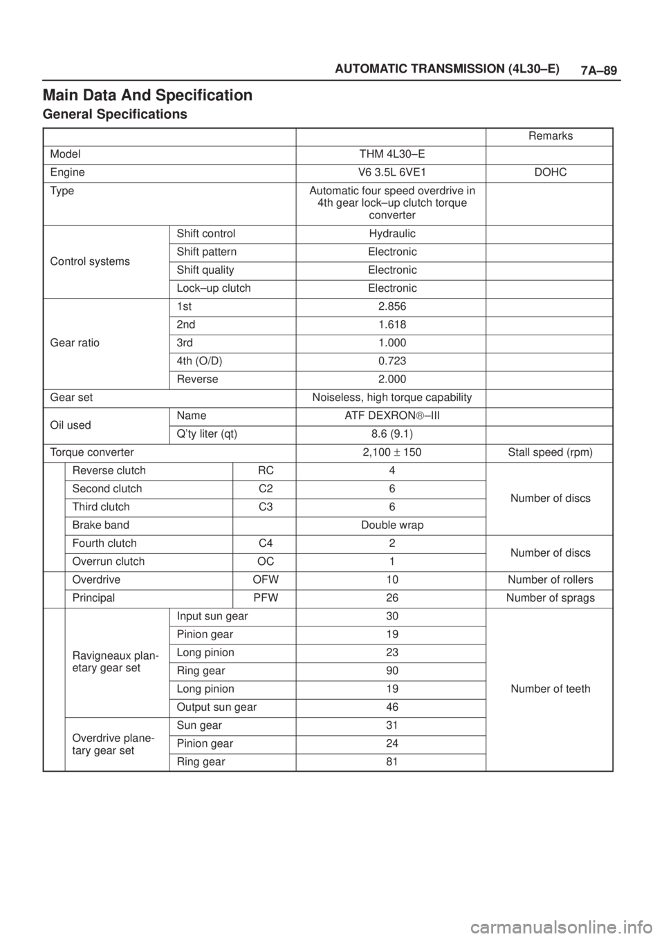
Main Data And Specification
General Specifications
Remarks
ModelTHM 4L30±E
EngineV6 3.5L 6VE1DOHC
TypeAutomatic four speed overdrive in
4th gear lock±up clutch torque
converter
Shift controlHydraulic
Control systemsShift patternElectronicControl systemsShift qualityElectronic
Lock±up clutchElectronic
1st2.856
2nd1.618
Gear ratio3rd1.000
4th (O/D)0.723
Reverse2.000
Gear setNoiseless, high torque capability
Oil usedNameATF DEXRON)±IIIOil usedQ'ty liter (qt)8.6 (9.1)
Torque converter2,100 + 150Stall speed (rpm)
Reverse clutchRC4
Second clutchC26Number of discsThird clutchC36Number of discs
Brake bandDouble wrap
Fourth clutchC42Number of discsOverrun clutchOC1Number of discs
OverdriveOFW10Number of rollers
PrincipalPFW26Number of sprags
Input sun gear30
Pinion gear19
Ravigneaux plan-Long pinion23g
etary gear setRing gear90
Long pinion19Number of teeth
Output sun gear46
Odi l
Sun gear31
Overdrive plane-
tary gear setPinion gear24tary gear set
Ring gear81