ISUZU KB P190 2007 Workshop Repair Manual
KB P190 2007
ISUZU
ISUZU
https://www.carmanualsonline.info/img/61/57177/w960_57177-0.png
ISUZU KB P190 2007 Workshop Repair Manual
Page 5342 of 6020
8A-404 ELECTRICAL-BODY AND CHASSIS
CIRCUIT DIAGRAM 4JJ1-TC/4JK1-TC (LHD) G.EXP G.EXP TYPE
RTW 78AXF023301
BACK TO CHAPTER INDEX TO MODEL INDEXISUZU KB P190 2007
Page 5343 of 6020
ELECTRICAL-BODY AND CHASSIS 8A-405
CIRCUIT DIAGRAM 4JH1 (LHD) STD TYPE
RTW 78AXF013801
BACK TO CHAPTER INDEX
TO MODEL INDEXISUZU KB P190 2007
Page 5344 of 6020
8A-406 ELECTRICAL-BODY AND CHASSIS
CIRCUIT DIAGRAM 4JH1 (LHD) WITHOUT ANTI THEFT G.EXP TYPE
RTW 78AXF013701
BACK TO CHAPTER INDEX
TO MODEL INDEXISUZU KB P190 2007
Page 5346 of 6020

8A-408 ELECTRICAL-BODY AND CHASSIS
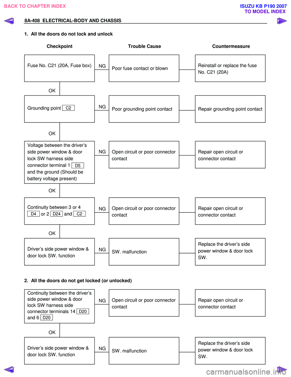
1. All the doors do not lock and unlock
Checkpoint Trouble Cause Countermeasure
Reinstall or replace the fuse
No. C21 (20A)
Poor fuse contact or blown
NG
Repair grounding point contact
Grounding point C2
Poor grounding point contact
Repair open circuit or
connector contact
Voltage between the driver’s
side power window & door
lock SW harness side
connector terminal 1
D5
and the ground (Should be
battery voltage present)
Open circuit or poor connector
contact
NG
NG
OK
OK
OK
Fuse No. C21 (20A, Fuse box)
Repair open circuit or
connector contact
Open circuit or poor connector
contact
NG
Replace the driver’s side
power window & door lock
SW .
Driver’s side power window &
door lock SW . function
SW . malfunction
NG
OK
Continuity between 3 or 4
D4 or 2 D24 and
C2
2. All the doors do not get locked (or unlocked)
Repair open circuit or
connector contact
Open circuit or poor connector
contact
NG
Replace the driver’s side
power window & door lock
SW .
Driver’s side power window &
door lock SW . function
SW . malfunction
NG
OK
Continuity between the driver’s
side power window & door
lock SW harness side
connector terminals 14
D20
and 6
D20
BACK TO CHAPTER INDEX TO MODEL INDEXISUZU KB P190 2007
Page 5350 of 6020
8A-412 ELECTRICAL-BODY AND CHASSIS
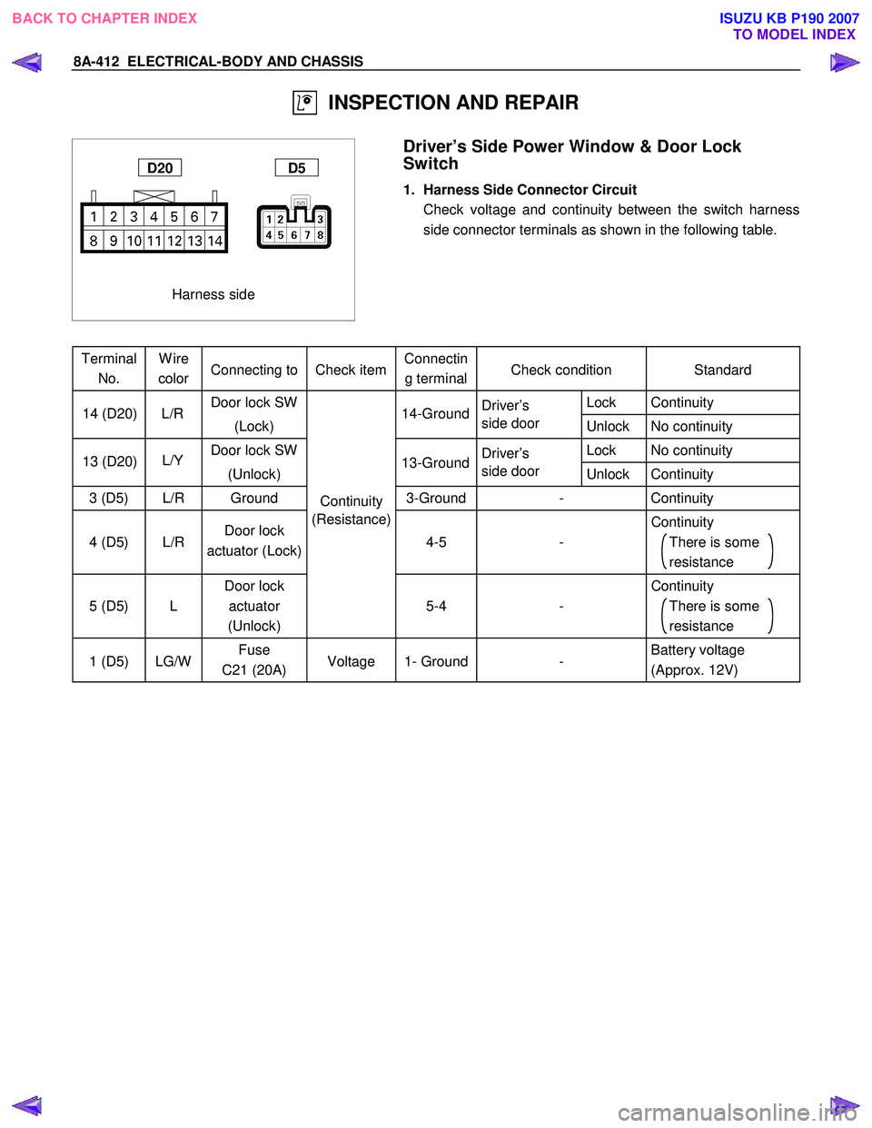
INSPECTION AND REPAIR
Harness side
D20 D5
Driver’s Side Power Window & Door Lock
Switch
1. Harness Side Connector Circuit
Check voltage and continuity between the switch harness side connector terminals as shown in the following table.
Terminal No. Wire
color Connecting to Check item Connectin
g terminal Check condition
Standard
Door lock SW
Driver’s Lock Continuity
(Lock) side door
Unlock No continuity
Door lock SW
Driver’s Lock No continuity
(Unlock) side door
Unlock Continuity
3 (D5) L/R Ground Continuity 3-Ground
- Continuity
4 (D5)
L/R Door lock
actuator (Lock) (Resistance)
4-5
- Continuity
There is some
resistance
5 (D5)
L Door lock
actuator
(Unlock)
5-4
- Continuity
There is some
resistance
1 (D5) LG/W Fuse
C21 (20A) Voltage 1- Ground
- Battery voltage
(Approx. 12V)
14-Ground
L/R
14 (D20)
13-Ground
L/Y
13 (D20)
BACK TO CHAPTER INDEX
TO MODEL INDEXISUZU KB P190 2007
Page 5351 of 6020
ELECTRICAL-BODY AND CHASSIS 8A-413
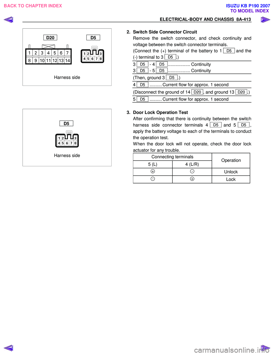
Harness side
D20 D5
2. Switch Side Connector Circuit
Remove the switch connector, and check continuity and voltage between the switch connector terminals.
(Connect the (+) terminal of the battery to 1
D5and the
(-) terminal to 3
D5.)
3
D5 - 4 D5.................. Continuity
3 D5 - 5 D5.................. Continuity
(Then, ground 3 D5.)
4
D5.......... Current flow for approx. 1 second
(Disconnect the ground of 14 D20 , and ground 13 D20.)
5
D5.......... Current flow for approx. 1 second
Harness side
D5
3. Door Lock Operation Test
After confirming that there is continuity between the switch
harness side connector terminals 4
D5 and 5 D5,
apply the battery voltage to each of the terminals to conduct
the operation test.
W hen the door lock will not operate, check the door lock actuator for any trouble.
Connecting terminals
5 (L) 4 (L/R)
+ - Unlock
- + Lock
Operation
BACK TO CHAPTER INDEX TO MODEL INDEXISUZU KB P190 2007
Page 5352 of 6020

8A-414 ELECTRICAL-BODY AND CHASSIS
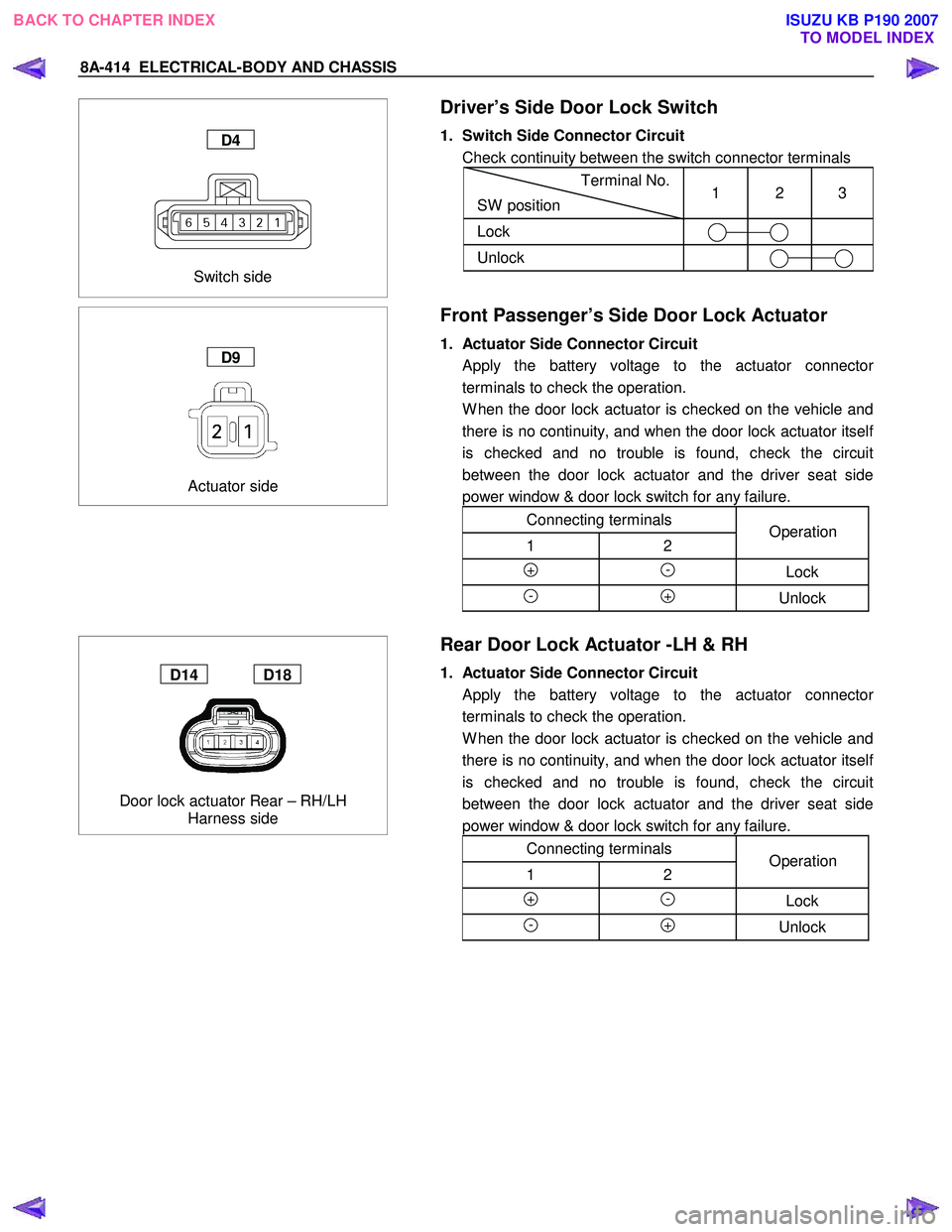
Switch side
D4
Driver’s Side Door Lock Switch
1. Switch Side Connector Circuit
Check continuity between the switch connector terminals
Terminal No.
SW position 1 2 3
Lock
Unlock
Actuator side
D9
Front Passenger’s Side Door Lock Actuator
1. Actuator Side Connector Circuit
Apply the battery voltage to the actuator connecto
r
terminals to check the operation.
W hen the door lock actuator is checked on the vehicle and there is no continuity, and when the door lock actuator itsel
f
is checked and no trouble is found, check the circuit
between the door lock actuator and the driver seat side
power window & door lock switch for any failure.
Connecting terminals
1 2
+ - Lock
- + Unlock
Operation
Door lock actuator Rear – RH/LH Harness side
D14 D18
Rear Door Lock Actuator -LH & RH
1. Actuator Side Connector Circuit
Apply the battery voltage to the actuator connecto
r
terminals to check the operation.
W hen the door lock actuator is checked on the vehicle and there is no continuity, and when the door lock actuator itsel
f
is checked and no trouble is found, check the circuit
between the door lock actuator and the driver seat side
power window & door lock switch for any failure.
Connecting terminals
1 2
+ - Lock
- + Unlock
Operation
BACK TO CHAPTER INDEX TO MODEL INDEXISUZU KB P190 2007
Page 5357 of 6020
ELECTRICAL-BODY AND CHASSIS 8A-419
CIRCUIT DIAGRAM C24SE (RHD)
RTW 680XF013001
BACK TO CHAPTER INDEX
TO MODEL INDEXISUZU KB P190 2007
Page 5358 of 6020
8A-420 ELECTRICAL-BODY AND CHASSIS
CIRCUIT DIAGRAM HFV6 (RHD)
RTW 78AXF003501
BACK TO CHAPTER INDEX
TO MODEL INDEXISUZU KB P190 2007
Page 5359 of 6020
ELECTRICAL-BODY AND CHASSIS 8A-421
CIRCUIT DIAGRAM 4JJ1-TC/4JK1-TC (RHD) EXCEPT SOUTH AFRICA
RTW 78AXF017801
BACK TO CHAPTER INDEX
TO MODEL INDEXISUZU KB P190 2007


