engine coolant ISUZU KB P190 2007 Workshop User Guide
[x] Cancel search | Manufacturer: ISUZU, Model Year: 2007, Model line: KB P190, Model: ISUZU KB P190 2007Pages: 6020, PDF Size: 70.23 MB
Page 837 of 6020
6A – 32 ENGINE MECHANICAL
COMPRESSION PRESSURE
MEASUREMENT
1. Start the engine and allow it to idle until the coolant
temperature reaches 70 – 80 °C (158 – 176 °F).
2. Remove the following parts.
• Leak off pipe
• Injection nozzle holder bracket
• Injection nozzle holder
3. Install the following parts.
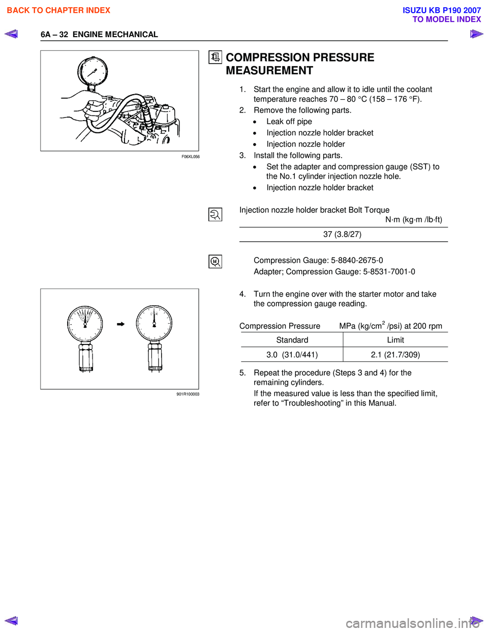
• Set the adapter and compression gauge (SST) to
the No.1 cylinder injection nozzle hole.
• Injection nozzle holder bracket
Injection nozzle holder bracket Bolt Torque
N·m (kg·m /lb·ft)
37 (3.8/27)
Compression Gauge: 5-8840-2675-0
Adapter; Compression Gauge: 5-8531-7001-0
4. Turn the engine over with the starter motor and take the compression gauge reading.
Compression Pressure MPa (kg/cm
2 /psi) at 200 rpm
Standard Limit
3.0 (31.0/441) 2.1 (21.7/309)
5. Repeat the procedure (Steps 3 and 4) for the
remaining cylinders.
If the measured value is less than the specified limit,
refer to “Troubleshooting” in this Manual.
F06XL056
901R100003
BACK TO CHAPTER INDEX
TO MODEL INDEX
ISUZU KB P190 2007
Page 839 of 6020
6A – 34 ENGINE MECHANICAL
RTW 46ASH000701
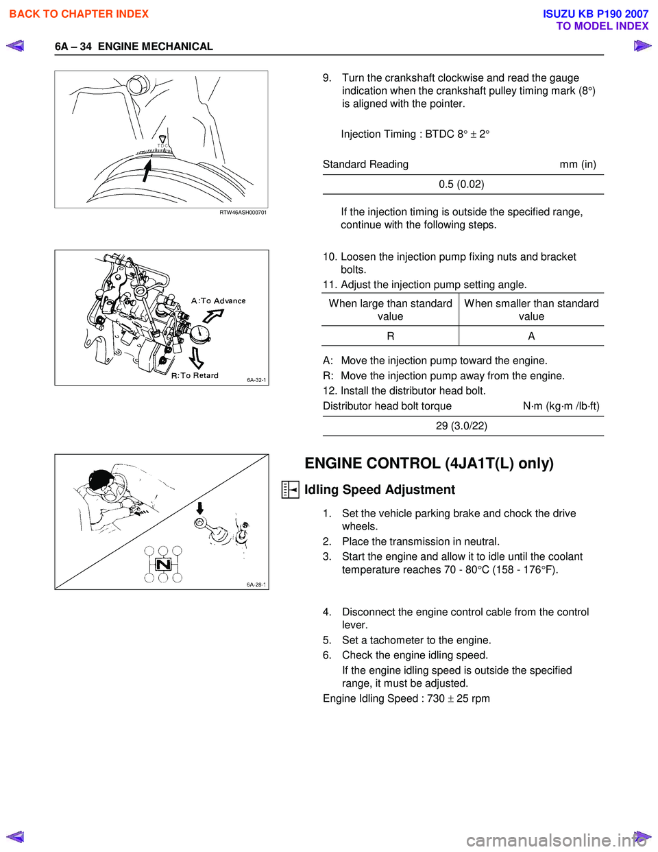
9. Turn the crankshaft clockwise and read the gauge
indication when the crankshaft pulley timing mark (8 °)
is aligned with the pointer.
Injection Timing : BTDC 8 ° ± 2 °
Standard Reading mm (in)
0.5 (0.02)
If the injection timing is outside the specified range,
continue with the following steps.
10. Loosen the injection pump fixing nuts and bracket bolts.
11. Adjust the injection pump setting angle.
W hen large than standard value W hen smaller than standard
value
R A
A: Move the injection pump toward the engine.
R: Move the injection pump away from the engine.
12. Install the distributor head bolt.
Distributor head bolt torque N·m (kg·m /lb·ft)
29 (3.0/22)
ENGINE CONTROL (4JA1T(L) only)
Idling Speed Adjustment
1. Set the vehicle parking brake and chock the drive wheels.
2. Place the transmission in neutral.
3. Start the engine and allow it to idle until the coolant temperature reaches 70 - 80 °C (158 - 176 °F).
4. Disconnect the engine control cable from the control lever.
5. Set a tachometer to the engine.
6. Check the engine idling speed. If the engine idling speed is outside the specified
range, it must be adjusted.
Engine Idling Speed : 730 ± 25 rpm
BACK TO CHAPTER INDEX
TO MODEL INDEX
ISUZU KB P190 2007
Page 844 of 6020
ENGINE MECHANICAL 6A – 39
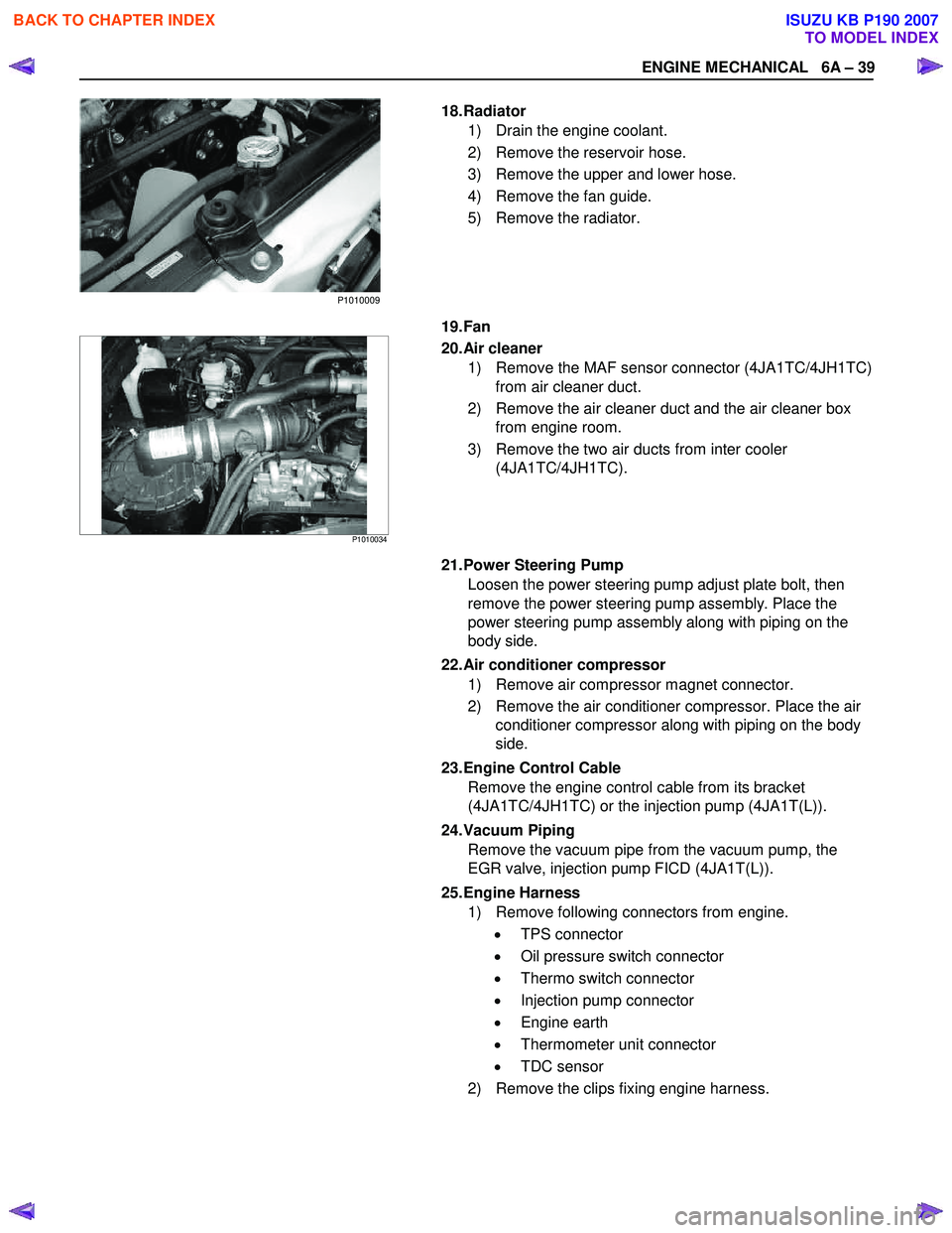
18. Radiator 1) Drain the engine coolant.
2) Remove the reservoir hose.
3) Remove the upper and lower hose.
4) Remove the fan guide.
5) Remove the radiator.
19. Fan
P1010034
20. Air cleaner
1) Remove the MAF sensor connector (4JA1TC/4JH1TC) from air cleaner duct.
2) Remove the air cleaner duct and the air cleaner box from engine room.
3) Remove the two air ducts from inter cooler (4JA1TC/4JH1TC).
21. Power Steering Pump Loosen the power steering pump adjust plate bolt, then
remove the power steering pump assembly. Place the
power steering pump assembly along with piping on the
body side.
22. Air conditioner compressor 1) Remove air compressor magnet connector.
2) Remove the air conditioner compressor. Place the air conditioner compressor along with piping on the body
side.
23. Engine Control Cable Remove the engine control cable from its bracket
(4JA1TC/4JH1TC) or the injection pump (4JA1T(L)).
24. Vacuum Piping Remove the vacuum pipe from the vacuum pump, the
EGR valve, injection pump FICD (4JA1T(L)).
25. Engine Harness 1) Remove following connectors from engine.
• TPS connector
• Oil pressure switch connector
• Thermo switch connector
• Injection pump connector
• Engine earth
• Thermometer unit connector
• TDC sensor
2) Remove the clips fixing engine harness.
P1010009
BACK TO CHAPTER INDEX
TO MODEL INDEX
ISUZU KB P190 2007
Page 846 of 6020
ENGINE MECHANICAL 6A – 41
Coolant Replenishment
Warning:
When the coolant is heated to a high temperature, be
sure not to loosen or remove the rediator cap.
Otherwise you might get scalded by hot vapor or
boiling water.
To open the radiator cap, put a piece of thick cloth on
the cap and loosen the cap slowly to reduce the
pressure when the coolant has become cooler.
1. Open rediator cap pour coolant up to filler neck
2. Pour coolant into reservoir tank up to "MAX" line
3. Tighten radiator cap and start the engine. After idling for 2 to 3 minutes, stop the engine and reopen radiator
cap. If the water level is lower, replenish.
4. After replenish the coolant tighten radiator cap, warm up the engine at about 2000 rpm. Set heater
adjustment to the highest temperature position, and let
the coolant circulate also into heater water system.
5. Check to see the thermometer, continuously idling 5 minutes and stop the engine.
6. W hen the engine has been cooled, check filler neck for water level and replenish if required. Should extreme
shortage of coolant is found, check the coolant system
and reservoir tank hose for leakage.
7. Pour coolant into the reservoir tank up to "MAX" line.
Coolant Capacity lit (US/UK gal)
4JA1 / TC 9.4 (2.5 / 2.1)
4JH1TC M/T: 10.1 (2.7 / 2.2)
A/T: 10.0 (2.6 / 2.2)
Engine Warm-Up
After completing the required maintenance procedures,
start the engine and allow it to idle until it is warm.
Check the following:
1. Engine idling speed.
2. Engine noise level.
3. Engine lubricating system and cooling system. Carefully check for oil and coolant leakage.
4. Clutch engagement.
5. Transmission operation.
6. Indicator warning light operation.
BACK TO CHAPTER INDEX
TO MODEL INDEX
ISUZU KB P190 2007
Page 945 of 6020

SECTION 6B
ENGINE COOLING
TABLE OF CONTENTS
PAGE
Main Data and Specifications ....................................................................................... 6B - 3
General Description .................................................................................................. 6B - 4
Coolant Flow .............................................................................................................. 6B - 4
Water Pump ............................................................................................................... 6B - 5
Thermostat................................................................................................................. 6B - 5
Radiator...................................................................................................................... 6B - 6
Diagnosis ...................................................................................................................... . 6B - 7
Draining and Refilling Cooling System ....................................................................... 6B - 8
Water Pump ................................................................................................................... 6 B - 10
Removal and Installation .......................................................................................... 6B - 10
Removal ..................................................................................................................... 6 B - 10
Inspection and Repair ............................................................................................... 6B - 11
Installation ................................................................................................................. 6B - 11
Thermostat ..................................................................................................................... 6B - 13
Removal and Installation .......................................................................................... 6B - 13
Removal ..................................................................................................................... 6 B - 13
Inspection and Repair ............................................................................................... 6B - 13
Installation ................................................................................................................. 6B - 14
Radiator ....................................................................................................................... ... 6B - 15
Removal and Installation .......................................................................................... 6B - 15
Radiator and Associated Parts ................................................................................ 6B - 15
Removal ..................................................................................................................... 6 B - 16
Inspection and Repair ............................................................................................... 6B - 17
Installation ................................................................................................................. 6B - 18
EN GI NE COOLI NG 6 B – 1
BACK TO CHAPTER INDEX
TO MODEL INDEX
ISUZU KB P190 2007
Page 946 of 6020

6B – 2 ENGINE COOLING
PAGE
Engine coolant change ............................................................................................. 6B - 19
Fan Clutch with Cooling Fan ........................................................................................ 6B - 20
Inspection and Repair ............................................................................................... 6B - 20
Special Tools ............................................................................................................. 6B - 20
BACK TO CHAPTER INDEX
TO MODEL INDEX
ISUZU KB P190 2007
Page 947 of 6020
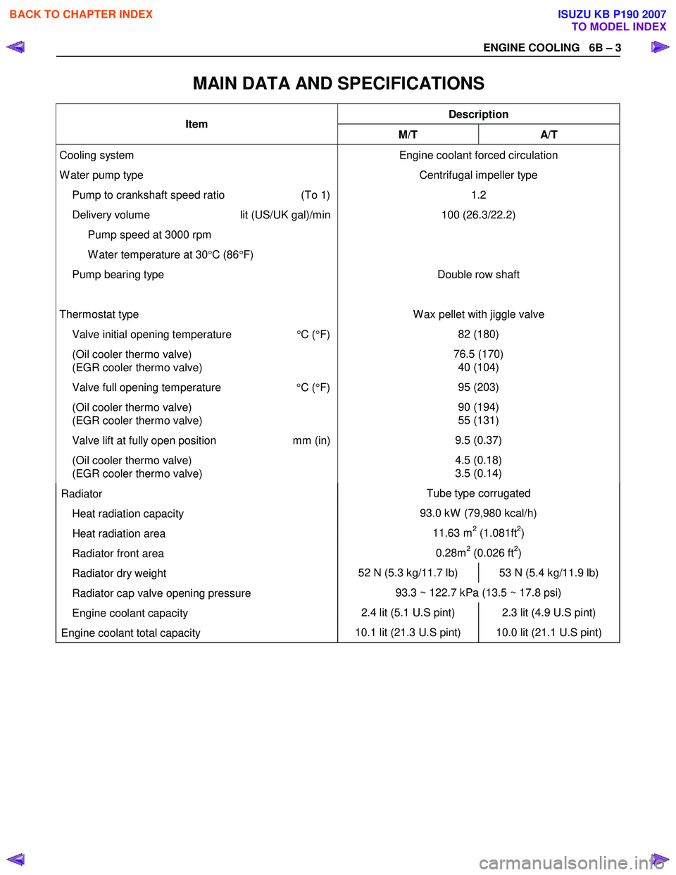
ENGINE COOLING 6B – 3
MAIN DATA AND SPECIFICATIONS
Description Item M/T A/T
Cooling system
W ater pump type
Pump to crankshaft speed ratio (To 1)
Delivery volume lit (US/UK gal)/min
Pump speed at 3000 rpm
W ater temperature at 30 °C (86 °F)
Pump bearing type
Thermostat type
Valve initial opening temperature °C ( °F)
(Oil cooler thermo valve)
(EGR cooler thermo valve)
Valve full opening temperature °C ( °F)
(Oil cooler thermo valve)
(EGR cooler thermo valve)
Valve lift at fully open position mm (in)
(Oil cooler thermo valve)
(EGR cooler thermo valve) Engine coolant forced circulation
Centrifugal impeller type 1.2
100 (26.3/22.2)
Double row shaft
W ax pellet with jiggle valve 82 (180)
76.5 (170) 40 (104)
95 (203)
90 (194)
55 (131)
9.5 (0.37)
4.5 (0.18)
3.5 (0.14)
Radiator Tube type corrugated
Heat radiation capacity 93.0 kW (79,980 kcal/h)
Heat radiation area 11.63 m2 (1.081ft2)
Radiator front area 0.28m2 (0.026 ft2)
Radiator dry weight 52 N (5.3 kg/11.7 lb) 53 N (5.4 kg/11.9 lb)
Radiator cap valve opening pressure 93.3 ~ 122.7 kPa (13.5 ~ 17.8 psi)
Engine coolant capacity 2.4 lit (5.1 U.S pint) 2.3 lit (4.9 U.S pint)
Engine coolant total capacity 10.1 lit (21.3 U.S pint) 10.0 lit (21.1 U.S pint)
BACK TO CHAPTER INDEX
TO MODEL INDEX
ISUZU KB P190 2007
Page 948 of 6020

6B – 4 ENGINE COOLING
GENERAL DESCRIPTION
COOLANT FLOW
RTW 66ALF000101
The engine cooling system consists of the radiator, the water pump, the cooling fan, and the thermostat.
To quickly increase cold engine coolant temperature for smooth engine operation, the coolant is circulated by the
water pump and thermostat through the bypass hose and back to the cylinder body.
The coolant does not circulate through the radiator.
W hen the coolant temperature reaches specified value, the thermostat will begin to open and a gradually increasing
amount of coolant will circulate through the radiator.
The thermostat will be fully open when the coolant temperature reaches specified value. All of the coolant is now
circulating through the radiator for effective engine cooling.
BACK TO CHAPTER INDEX
TO MODEL INDEX
ISUZU KB P190 2007
Page 949 of 6020

ENGINE COOLING 6B – 5
WATER PUMP
RTW 46ASF000101
A centrifugal type water pump forcefully circulates the coolant through the cooling system.
The water pump is not disassembled type.
THERMOSTAT
030RY00005
A wax pellet type thermostat is used.
The jiggle valve accelerates engine warm-up.
BACK TO CHAPTER INDEX
TO MODEL INDEX
ISUZU KB P190 2007
Page 950 of 6020
6B – 6 ENGINE COOLING
110RS001
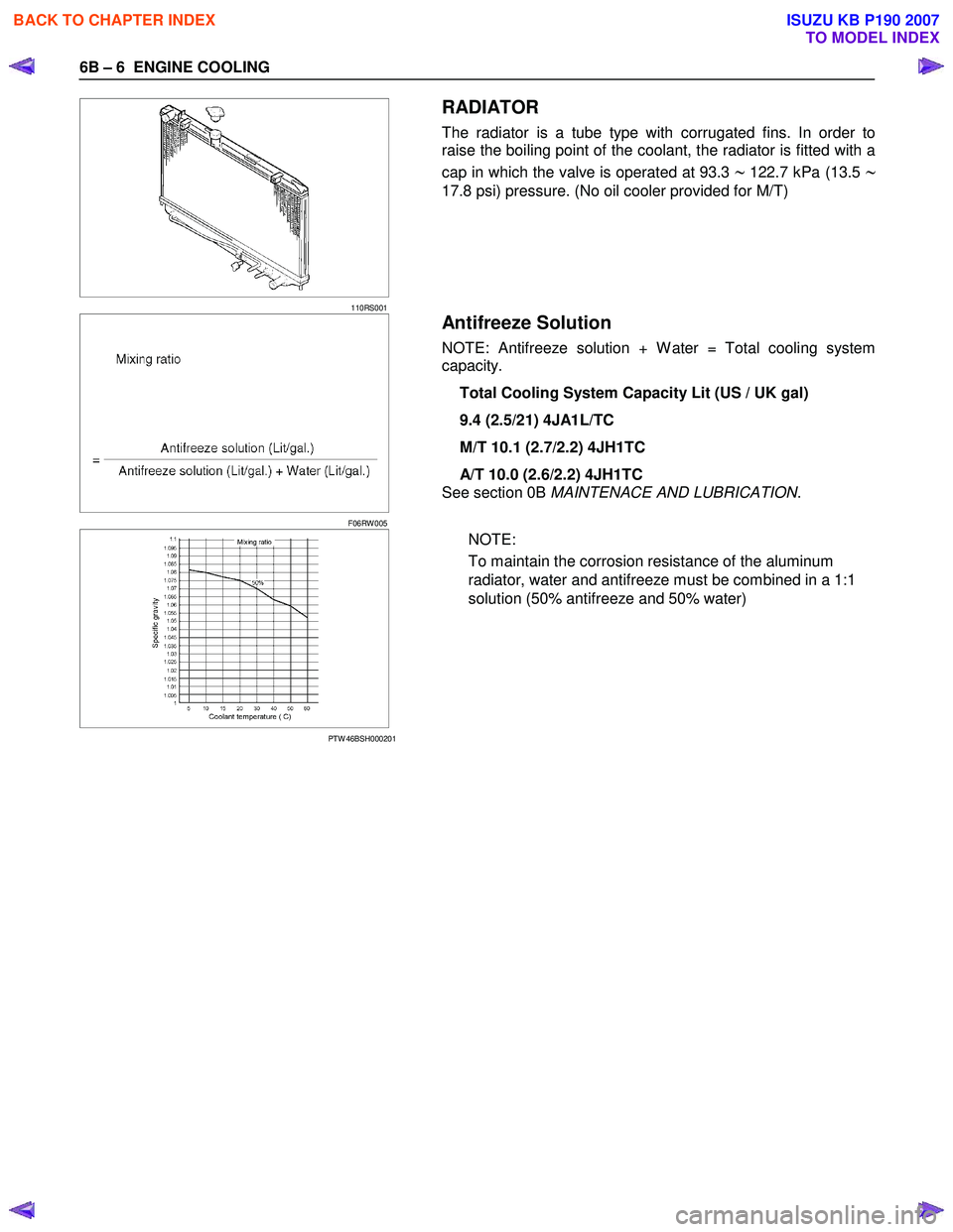
RADIATOR
The radiator is a tube type with corrugated fins. In order to
raise the boiling point of the coolant, the radiator is fitted with a
cap in which the valve is operated at 93.3
∼ 122.7 kPa (13.5 ∼
17.8 psi) pressure. (No oil cooler provided for M/T)
F06RW 005
Antifreeze Solution
NOTE: Antifreeze solution + W ater = Total cooling system
capacity.
Total Cooling System Capacity Lit (US / UK gal)
9.4 (2.5/21) 4JA1L/TC
M/T 10.1 (2.7/2.2) 4JH1TC
A/T 10.0 (2.6/2.2) 4JH1TC
See section 0B MAINTENACE AND LUBRICATION .
PTW 46BSH000201
NOTE:
To maintain the corrosion resistance of the aluminum
radiator, water and antifreeze must be combined in a 1:1
solution (50% antifreeze and 50% water)
BACK TO CHAPTER INDEX
TO MODEL INDEX
ISUZU KB P190 2007