power steering fluid ISUZU KB P190 2007 Workshop User Guide
[x] Cancel search | Manufacturer: ISUZU, Model Year: 2007, Model line: KB P190, Model: ISUZU KB P190 2007Pages: 6020, PDF Size: 70.23 MB
Page 280 of 6020
POWER-ASSISTED STEERING SYSTEM 3B-19
Disassembly
1. Clean the oil pump with solvent (plug the discharge
and suction ports to prevent the entry of solvent).
Be careful not to expose the oil seal of shaft
assembly to solvent.
2. Remove the bolt, suction pipe and O-ring.
3. Remove the connector, O-ring, relief valve and spring.
4. Remove the bolt, rear housing and O-ring.
5. Remove the snap ring.
6. Remove the shaft assembly.
7. Remove the oil seal.
CAUTION: When removing the oil seal, be careful
not to damage the housing.
8. Remove the pump cartridge assembly from the front housing.
9. Remove two O-rings.
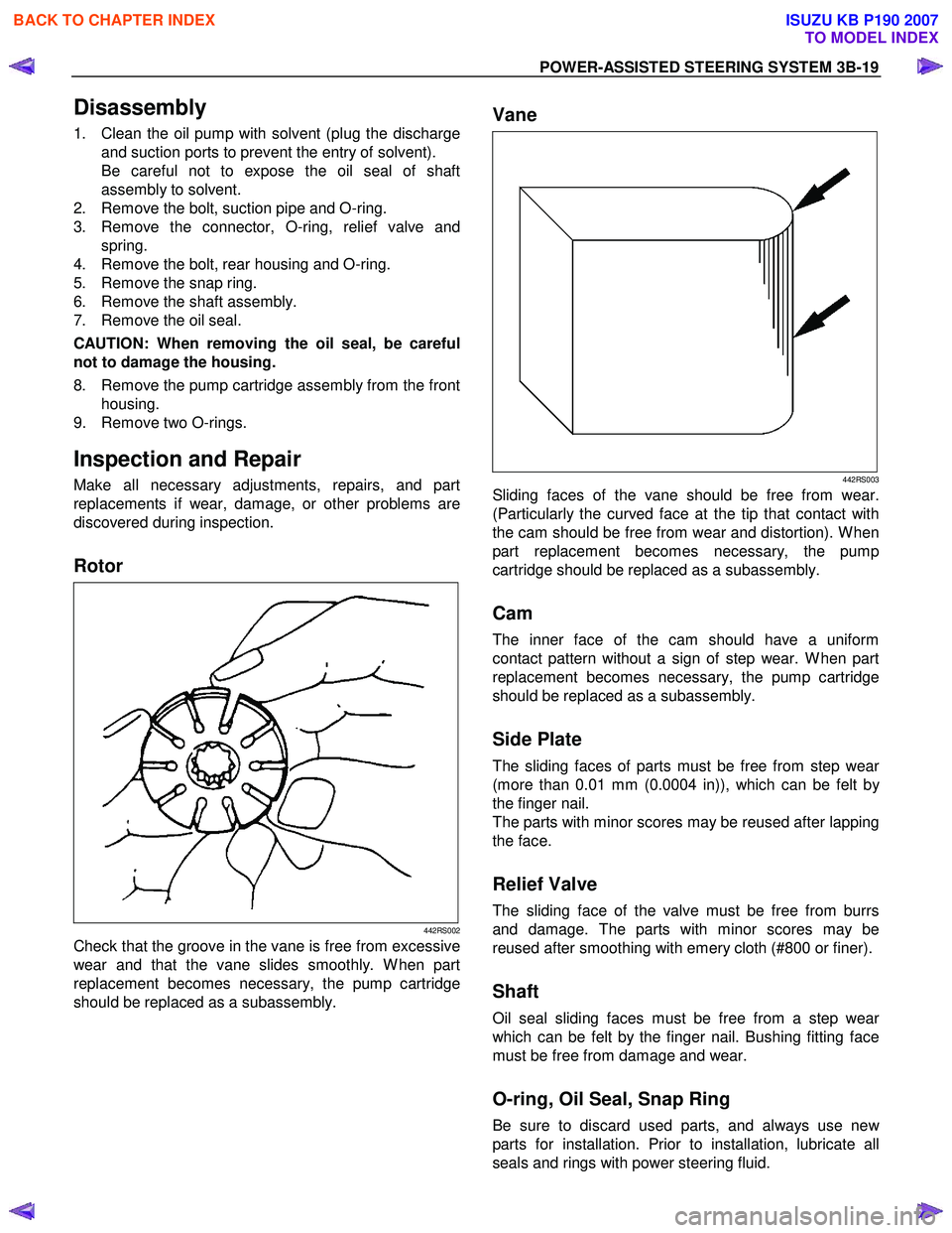
Inspection and Repair
Make all necessary adjustments, repairs, and part
replacements if wear, damage, or other problems are
discovered during inspection.
Rotor
442RS002
Check that the groove in the vane is free from excessive
wear and that the vane slides smoothly. W hen part
replacement becomes necessary, the pump cartridge
should be replaced as a subassembly.
Vane
442RS003
Sliding faces of the vane should be free from wear.
(Particularly the curved face at the tip that contact with
the cam should be free from wear and distortion). W hen
part replacement becomes necessary, the pump
cartridge should be replaced as a subassembly.
Cam
The inner face of the cam should have a uniform
contact pattern without a sign of step wear. W hen part
replacement becomes necessary, the pump cartridge
should be replaced as a subassembly.
Side Plate
The sliding faces of parts must be free from step wear
(more than 0.01 mm (0.0004 in)), which can be felt b
y
the finger nail.
The parts with minor scores may be reused after lapping
the face.
Relief Valve
The sliding face of the valve must be free from burrs
and damage. The parts with minor scores may be
reused after smoothing with emery cloth (#800 or finer).
Shaft
Oil seal sliding faces must be free from a step wear
which can be felt by the finger nail. Bushing fitting face
must be free from damage and wear.
O-ring, Oil Seal, Snap Ring
Be sure to discard used parts, and always use new
parts for installation. Prior to installation, lubricate all
seals and rings with power steering fluid.
BACK TO CHAPTER INDEX
TO MODEL INDEX
ISUZU KB P190 2007
Page 281 of 6020
3B-20 POWER-ASSISTED STEERING SYSTEM
Reassembly
1. Install oil seal to front housing. Be sure to discard
used oil seal, and always use new parts fo
r
installation.
CAUTION: When installing the oil seal, be careful
not to damage the oil seal contacting surface of the
housing.
2. Install shaft assembly.
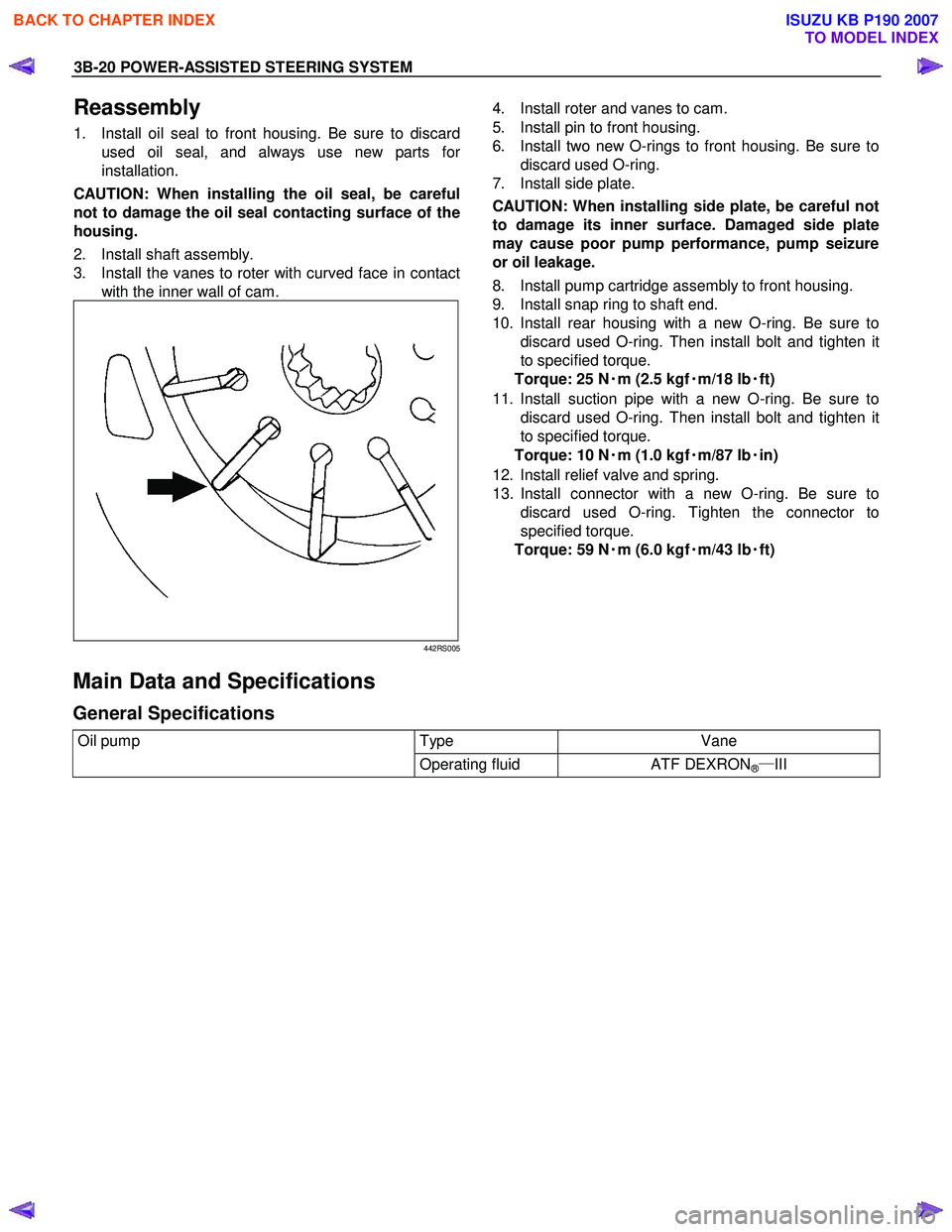
3. Install the vanes to roter with curved face in contact with the inner wall of cam.
442RS005
4. Install roter and vanes to cam.
5. Install pin to front housing.
6. Install two new O-rings to front housing. Be sure to discard used O-ring.
7. Install side plate.
CAUTION: When installing side plate, be careful not
to damage its inner surface. Damaged side plate
may cause poor pump performance, pump seizure
or oil leakage.
8. Install pump cartridge assembly to front housing.
9. Install snap ring to shaft end.
10. Install rear housing with a new O-ring. Be sure to discard used O-ring. Then install bolt and tighten it
to specified torque.
Torque: 25 N ・
・・
・
m (2.5 kgf ・
・・
・
m/18 lb ・
・・
・
ft)
11. Install suction pipe with a new O-ring. Be sure to discard used O-ring. Then install bolt and tighten it
to specified torque.
Torque: 10 N ・
・・
・
m (1.0 kgf ・
・・
・
m/87 lb ・
・・
・
in)
12. Install relief valve and spring.
13. Install connector with a new O-ring. Be sure to discard used O-ring. Tighten the connector to
specified torque.
Torque: 59 N ・
・・
・
m (6.0 kgf ・
・・
・
m/43 lb ・
・・
・
ft)
Main Data and Specifications
General Specifications
Oil pump Type Vane
Operating fluid
ATF DEXRON®―III
BACK TO CHAPTER INDEX
TO MODEL INDEX
ISUZU KB P190 2007
Page 283 of 6020
3B-22 POWER-ASSISTED STEERING SYSTEM
Power Steering Pump (4JJ1-TC, 4JK1-TC)
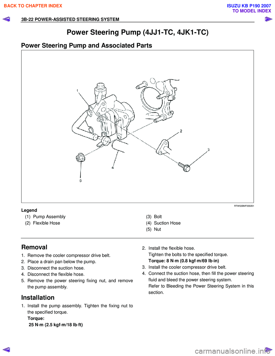
Power Steering Pump and Associated Parts
RTW 53BMF000201
Legend
(1) Pump Assembly
(2) Flexible Hose
(3) Bolt
(4) Suction Hose
(5) Nut
Removal
1. Remove the cooler compressor drive belt.
2. Place a drain pan below the pump.
3. Disconnect the suction hose.
4. Disconnect the flexible hose.
5. Remove the power steering fixing nut, and remove the pump assembly.
Installation
1. Install the pump assembly. Tighten the fixing nut to
the specified torque.
Torque: 25 N·m (2.5 kgf·m/18 lb·ft)
2. Install the flexible hose.
Tighten the bolts to the specified torque.
Torque: 8 N·m (0.8 kgf·m/69 lb·in)
3. Install the cooler compressor drive belt.
4. Connect the suction hose, then fill the power steering fluid and bleed the power steering system.
Refer to Bleeding the Power Steering System in this section.
BACK TO CHAPTER INDEX
TO MODEL INDEX
ISUZU KB P190 2007
Page 285 of 6020
3B-24 POWER-ASSISTED STEERING SYSTEM
Disassembly
1. Clean the oil pump with solvent (plug the discharge
and suction ports to prevent the entry of solvent).
Be careful not to expose the oil seal of the shaft assembly to solvent.
2. Remove the bolt, suction pipe and O-ring.
3. Remove the nut and bracket.
4. Remove the nut, washer and joint.
5. Remove the connector, O-ring, relief valve and spring.
6. Remove the bolt, rear housing and O-ring.
7. Remove the pump cartridge assembly and the side plate from the shaft. Remove two O-rings.
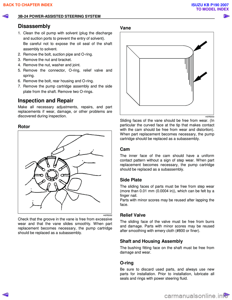
Inspection and Repair
Make all necessary adjustments, repairs, and part
replacements if wear, damage, or other problems are
discovered during inspection.
Rotor
442RS002
Check that the groove in the vane is free from excessive
wear and that the vane slides smoothly. W hen part
replacement becomes necessary, the pump cartridge
should be replaced as a subassembly.
Vane
442RS003
Sliding faces of the vane should be free from wear. (In
particular the curved face at the tip that makes contact
with the cam should be free from wear and distortion).
W hen part replacement becomes necessary, the pump
cartridge should be replaced as a subassembly.
Cam
The inner face of the cam should have a uniform
contact pattern without a sign of step wear. W hen part
replacement becomes necessary, the pump cartridge
should be replaced as a subassembly.
Side Plate
The sliding faces of parts must be free from step wear
(more than 0.01 mm (0.0004 in)), which can be felt by a
finger nail.
Parts with minor scores may be reused after lapping the
face.
Relief Valve
The sliding face of the valve must be free from burrs
and damage. Parts with minor scores may be reused
after smoothing with emery cloth (#800 or finer).
Shaft and Housing Assembly
The bushing fitting face on the shaft must be free from
damage and wear.
O-ring
Be sure to discard used parts, and always use new
parts for installation. Prior to installation, lubricate all
seals and rings with power steering fluid.
BACK TO CHAPTER INDEX
TO MODEL INDEX
ISUZU KB P190 2007
Page 286 of 6020
POWER-ASSISTED STEERING SYSTEM 3B-25
Reassembly
1. Install two new O-rings on shaft and housing
assembly. Be sure to discard used O-ring.
2. Install side plate.
CAUTION: When installing side plate, be careful not
to damage its inner surface. A damaged side plate
may cause poor pump performance, pump seizure
or oil leakage.
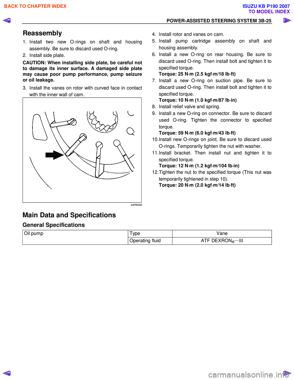
3. Install the vanes on rotor with curved face in contact with the inner wall of cam.
442RS005
4. Install rotor and vanes on cam.
5. Install pump cartridge assembly on shaft and housing assembly.
6. Install a new O-ring on rear housing. Be sure to discard used O-ring. Then install bolt and tighten it to
specified torque.
Torque: 25 N ⋅
⋅⋅
⋅
m (2.5 kgf ⋅
⋅⋅
⋅
m/18 lb ⋅
⋅⋅
⋅
ft)
7. Install a new O-ring on suction pipe. Be sure to
discard used O-ring. Then install bolt and tighten it to
specified torque.
Torque: 10 N ⋅
⋅⋅
⋅
m (1.0 kgf ⋅
⋅⋅
⋅
m/87 lb ⋅
⋅⋅
⋅
in)
8. Install relief valve and spring.
9. Install a new O-ring on connector. Be sure to discard used O-ring. Tighten the connector to specified
torque.
Torque: 59 N ⋅
⋅⋅
⋅
m (6.0 kgf ⋅
⋅⋅
⋅
m/43 lb ⋅
⋅⋅
⋅
ft)
10. Install new O-rings on joint. Be sure to discard used
O-rings. Temporarily tighten the nut with washer.
11. Install bracket. Then install nut and tighten it to specified torque.
Torque: 12 N ⋅
⋅⋅
⋅
m (1.2 kgf ⋅
⋅⋅
⋅
m/104 lb ⋅
⋅⋅
⋅
in)
12. Tighten the nut to the specified torque (This nut was
temporarily tightened in step 10).
Torque: 20 N ⋅
⋅⋅
⋅
m (2.0 kgf ⋅
⋅⋅
⋅
m/14 lb ⋅
⋅⋅
⋅
ft)
Main Data and Specifications
General Specifications
Oil pump Type Vane
Operating fluid
ATF DEXRON®―III
BACK TO CHAPTER INDEX
TO MODEL INDEX
ISUZU KB P190 2007
Page 2438 of 6020

6E–268 ENGINE DRIVEABILITY AND EMISSIONS
KNOCK SENSOR
Location
Right-hand side of the cylinder block.
Removal Procedure 1. Disconnect the negative battery cable.
2. Disconnect the knock sensor connector.
3. Loosen a bolt and remove knock sensor from the cylinder block.
Installation Procedure 1. Tighten the knock sensor by a bolt with specified tightening torque.
Tightening Torque
• Bolt: 20N·m (2.0kgf·m) 2. Connect a knock sensor connector to the knock sensor.
3. Connect the negative battery cable.
NOTE: Verify any DTCs (diagnosis Trouble Code) are
not stored after replacement.
POWER STEERING PRESSURE (PSP)
SWITCH
Location
Installed on the power steering pump assembly.
Removal Procedure 1. Disconnect the negative battery cable.
2. Disconnect the power steering pressure switch connector.
3. Loosen and remove the power steering pressure switch from the power steering pump.
Installation Procedure 1. Install the power steering pressure switch to the power steering pump.
2. Tighten the power steering pressure switch.
3. Connect a connector to the power steering pressure switch.
4. Connect the negative battery cable.
NOTE: Verify any DTCs (diagnosis Trouble Code) are
not stored after replacement.
Verify no power steering fluid leaking from the sensor
threads after replacement.
BACK TO CHAPTER INDEX
TO MODEL INDEX
ISUZU KB P190 2007
Page 2519 of 6020
Engine Mechanical – V6 Page 6A1–40
Cause Correction
W orn valve guides and or valve stems. Inspect and repair valves and valve guides as required,
refer to 3.22 Cylinder Head Assembly.
W orn or damaged valve stem oil seal. Replace valve stem oil seals as required, refer to 3.22
Cylinder Head Assembly.
Piston rings broken, worn or not seated correctly. Allowing adequate time for the piston rings to seat correctly,
replace piston rings as required, refer to 4.5 Pistons, Pins,
Rings, Connecting Rods and Big-end Bearings.
Piston rings incorrectly installed or not matched to cylinder
bore oversize. Replace piston rings as required, refer to 4.5 Pistons, Pins,
Rings, Connecting Rods and Big-end Bearings.
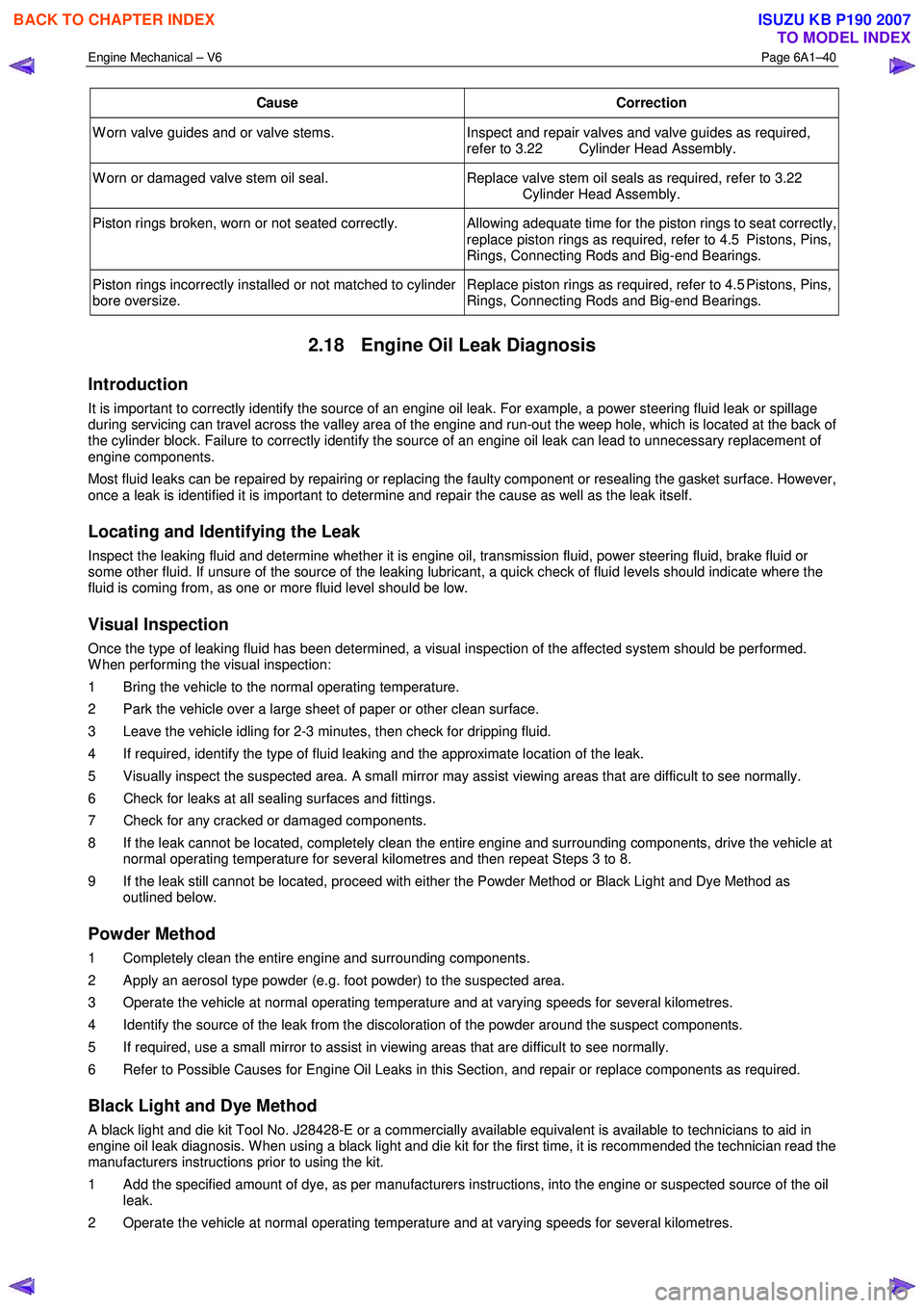
2.18 Engine Oil Leak Diagnosis
Introduction
It is important to correctly identify the source of an engine oil leak. For example, a power steering fluid leak or spillage
during servicing can travel across the valley area of the engine and run-out the weep hole, which is located at the back of
the cylinder block. Failure to correctly identify the source of an engine oil leak can lead to unnecessary replacement of
engine components.
Most fluid leaks can be repaired by repairing or replacing the faulty component or resealing the gasket surface. However,
once a leak is identified it is important to determine and repair the cause as well as the leak itself.
Locating and Identifying the Leak
Inspect the leaking fluid and determine whether it is engine oil, transmission fluid, power steering fluid, brake fluid or
some other fluid. If unsure of the source of the leaking lubricant, a quick check of fluid levels should indicate where the
fluid is coming from, as one or more fluid level should be low.
Visual Inspection
Once the type of leaking fluid has been determined, a visual inspection of the affected system should be performed.
W hen performing the visual inspection:
1 Bring the vehicle to the normal operating temperature.
2 Park the vehicle over a large sheet of paper or other clean surface.
3 Leave the vehicle idling for 2-3 minutes, then check for dripping fluid.
4 If required, identify the type of fluid leaking and the approximate location of the leak.
5 Visually inspect the suspected area. A small mirror may assist viewing areas that are difficult to see normally.
6 Check for leaks at all sealing surfaces and fittings.
7 Check for any cracked or damaged components.
8 If the leak cannot be located, completely clean the entire engine and surrounding components, drive the vehicle at normal operating temperature for several kilometres and then repeat Steps 3 to 8.
9 If the leak still cannot be located, proceed with either the Powder Method or Black Light and Dye Method as outlined below.
Powder Method
1 Completely clean the entire engine and surrounding components.
2 Apply an aerosol type powder (e.g. foot powder) to the suspected area.
3 Operate the vehicle at normal operating temperature and at varying speeds for several kilometres.
4 Identify the source of the leak from the discoloration of the powder around the suspect components.
5 If required, use a small mirror to assist in viewing areas that are difficult to see normally.
6 Refer to Possible Causes for Engine Oil Leaks in this Section, and repair or replace components as required.
Black Light and Dye Method
A black light and die kit Tool No. J28428-E or a commercially available equivalent is available to technicians to aid in
engine oil leak diagnosis. W hen using a black light and die kit for the first time, it is recommended the technician read the
manufacturers instructions prior to using the kit.
1 Add the specified amount of dye, as per manufacturers instructions, into the engine or suspected source of the oil leak.
2 Operate the vehicle at normal operating temperature and at varying speeds for several kilometres.
BACK TO CHAPTER INDEX
TO MODEL INDEX
ISUZU KB P190 2007
Page 2566 of 6020

Engine Mechanical – V6 Page 6A1–87
3.14 Crankshaft Front Seal
Replace
1 Remove the crankshaft balancer assembly, refer to 3.13 Crankshaft Balancer Assembly.
2 Using a flat bladed tool (2) or seal remover, Tool No. E-308, carefully remove the crankshaft front seal (1)
from the front cover.
Figure 6A1 – 81
3 Using crankshaft front seal installer, Tool No. J-29184 (2) and a suitable hammer, install a new crankshaft
front seal (1) until fully seated against the front cover
housing.
4 Install the crankshaft balancer assembly, refer to 3.13 Crankshaft Balancer Assembly.
CAUTION
Do not lubricate the crankshaft front oil seal
or crankshaft balancer sealing surfaces. The
crankshaft balancer is installed into a dry
seal.
Figure 6A1 – 82
3.15 Front Cover Assembly
Remove
1 Drain the engine coolant, refer to 6B1_Engine Cooling.
2 Remove the water outlet pipe and coolant pump assembly, refer to 6B1_ Engine Cooling:
3 Remove the camshaft covers, refer to 3.12 Camshaft Cover.
4 Remove the crankshaft balancer assembly, refer to 3.13 Crankshaft Balancer Assembly.
5 Disconnect the purge vent hose from the water outlet pipe.
NOTE
Do not disconnect the power steering pipes or
drain the power steering fluid.
6 Remove the power steering pump reservoir mounting bracket, refer to 3.8 Power Steering Pump Bracket.
7 Remove the camshaft position sensor, refer to 6C1-3 Engine Management – V6 – Service Operations.
BACK TO CHAPTER INDEX
TO MODEL INDEX
ISUZU KB P190 2007
Page 2677 of 6020
Engine Mechanical – V6 Page 6A1–198
k Timing chains, tensioners, shoes, guides & sprockets, refer to 3.16 Timing Chains, Tensioners, Shoes and
Guides.
l Cylinder head assemblies, refer to 3.22 Cylinder Head Assembly.
m Oil pan assembly, refer to 4.2 Oil Pan and Oil Pump Suction Pipe Assembly.
n Piston and connecting rod assemblies, refer to 4.5 Pistons, Pins, Rings, Connecting Rods and Big-end Bearings.
o Crankshaft assembly, refer to 4.6 Crankshaft and Main Bearings.
p Piston oil nozzles, refer 4.5 Pistons, Pins, Rings, Connecting Rods and Big-end Bearings.
Reassemble
Reassembly of the engine assembly is the reverse of the disassembly procedure.
Reinstall
Reinstallation of the engine assembly is the reverse to the removal procedure, noting the following:
NOTE
Refer to 6 Torque Wrench Specifications
for the correct torque specifications.
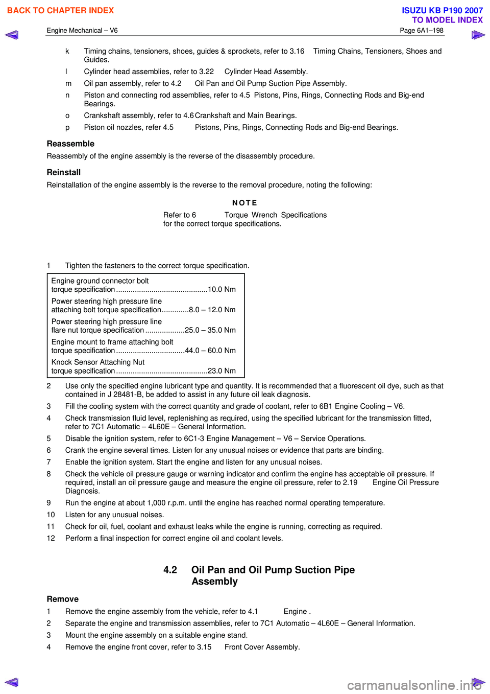
1 Tighten the fasteners to the correct torque specification.
Engine ground connector bolt
torque specification ............................................10.0 Nm
Power steering high pressure line
attaching bolt torque specification .............8.0 – 12.0 Nm
Power steering high pressure line
flare nut torque specification ...................25.0 – 35.0 Nm
Engine mount to frame attaching bolt
torque specification .................................44.0 – 60.0 Nm
Knock Sensor Attaching Nut
torque specification ............................................23.0 Nm
2 Use only the specified engine lubricant type and quantity. It is recommended that a fluorescent oil dye, such as that contained in J 28481-B, be added to assist in any future oil leak diagnosis.
3 Fill the cooling system with the correct quantity and grade of coolant, refer to 6B1 Engine Cooling – V6.
4 Check transmission fluid level, replenishing as required, using the specified lubricant for the transmission fitted, refer to 7C1 Automatic – 4L60E – General Information.
5 Disable the ignition system, refer to 6C1-3 Engine Management – V6 – Service Operations.
6 Crank the engine several times. Listen for any unusual noises or evidence that parts are binding.
7 Enable the ignition system. Start the engine and listen for any unusual noises.
8 Check the vehicle oil pressure gauge or warning indicator and confirm the engine has acceptable oil pressure. If required, install an oil pressure gauge and measure the engine oil pressure, refer to 2.19 Engine Oil Pressure
Diagnosis.
9 Run the engine at about 1,000 r.p.m. until the engine has reached normal operating temperature.
10 Listen for any unusual noises.
11 Check for oil, fuel, coolant and exhaust leaks while the engine is running, correcting as required.
12 Perform a final inspection for correct engine oil and coolant levels.
4.2 Oil Pan and Oil Pump Suction Pipe Assembly
Remove
1 Remove the engine assembly from the vehicle, refer to 4.1 Engine .
2 Separate the engine and transmission assemblies, refer to 7C1 Automatic – 4L60E – General Information.
3 Mount the engine assembly on a suitable engine stand.
4 Remove the engine front cover, refer to 3.15 Front Cover Assembly.
BACK TO CHAPTER INDEX
TO MODEL INDEX
ISUZU KB P190 2007
Page 2825 of 6020
Engine Mechanical – V6 Page 6A1–48
Page 6A1–48
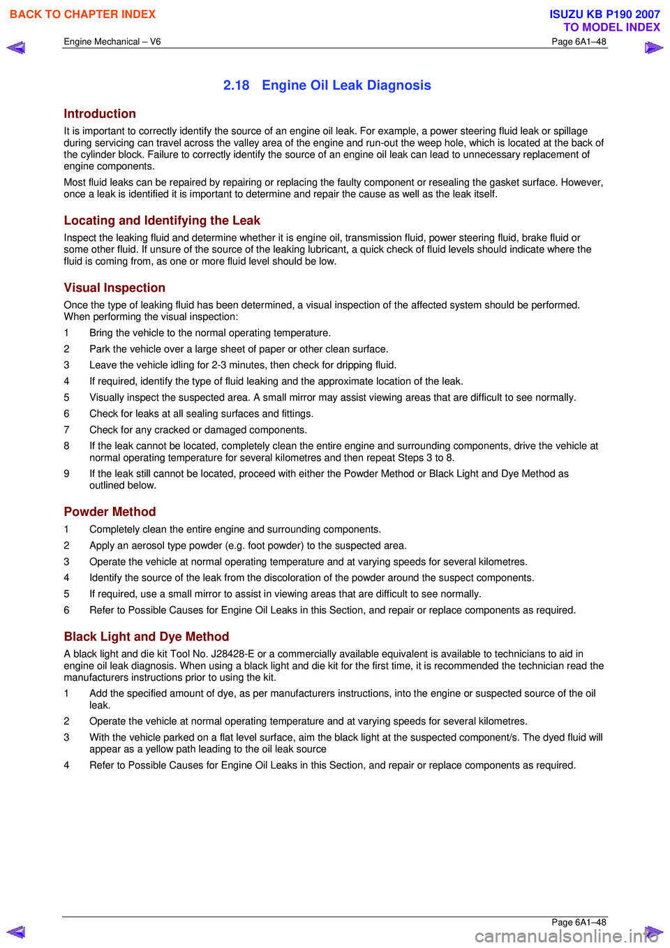
2.18 Engine Oil Leak Diagnosis
Introduction
It is important to correctly identify the source of an engine oil leak. For example, a power steering fluid leak or spillage
during servicing can travel across the va lley area of the engine and run-out the weep hole, which is located at the back of
the cylinder block. Failure to correctly identify the source of an engine oil leak can lead to unnecessary replacement of
engine components.
Most fluid leaks can be repaired by repairi ng or replacing the faulty component or resealing the gasket surface. However,
once a leak is identified it is im portant to determine and repair the c ause as well as the leak itself.
Locating and Identifying the Leak
Inspect the leaking fluid and determine whet her it is engine oil, transmission fluid, power steering fluid, brake fluid or
some other fluid. If unsure of the source of the leaking lubricant, a quick check of fluid levels should indicate where the
fluid is coming from, as one or more fluid level should be low.
Visual Inspection
Once the type of leaking fluid has been determined, a visual inspection of the affected system should be performed.
When performing the visual inspection:
1 Bring the vehicle to the normal operating temperature.
2 Park the vehicle over a large s heet of paper or other clean surface.
3 Leave the vehicle idling for 2-3 minut es, then check for dripping fluid.
4 If required, identify the type of fluid leak ing and the approximate location of the leak.
5 Visually inspect the suspected area. A small mirror may assist viewing areas that are difficult to see normally.
6 Check for leaks at all sealing surfaces and fittings.
7 Check for any cracked or damaged components.
8 If the leak cannot be located, completely clean the entire engine and surrounding components, drive the vehicle at
normal operating temperature for several k ilometres and then repeat Steps 3 to 8.
9 If the leak still cannot be located, proceed with either the Powder Method or Black Light and Dye Method as
outlined below.
Powder Method
1 Completely clean the entir e engine and surrounding components.
2 Apply an aerosol type powder (e.g. f oot powder) to the suspected area.
3 Operate the vehicle at normal operating temperature and at varying speeds for several kilometres.
4 Identify the source of the leak from the discoloration of the powder around the suspect components.
5 If required, use a small mirror to assist in vi ewing areas that are difficult to see normally.
6 Refer to Possible Causes for Engine Oil Leaks in this Section, and repair or replace components as required.
Black Light and Dye Method
A black light and die kit Tool No. J28428-E or a commercially av ailable equivalent is available to technicians to aid in
engine oil leak diagnosis. When using a black light and die kit fo r the first time, it is recommended the technician read the
manufacturers instructions prior to using the kit.
1 Add the specified amount of dye, as per manufacturers instructions, into the engine or suspected source of the oil
leak.
2 Operate the vehicle at normal operating temperature and at varying speeds for several kilometres.
3 With the vehicle parked on a flat leve l surface, aim the black light at the suspected component/s. The dyed fluid will
appear as a yellow path leading to the oil leak source
4 Refer to Possible Causes for Engine Oil Leaks in this Section, and repair or replace components as required.
BACK TO CHAPTER INDEX
TO MODEL INDEX
ISUZU KB P190 2007