timing belt ISUZU KB P190 2007 Workshop User Guide
[x] Cancel search | Manufacturer: ISUZU, Model Year: 2007, Model line: KB P190, Model: ISUZU KB P190 2007Pages: 6020, PDF Size: 70.23 MB
Page 2050 of 6020
6A-36 ENGINE MECHANICAL (C24SE)
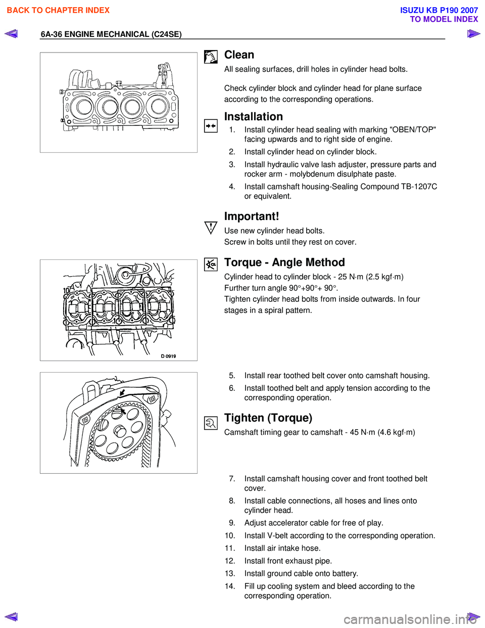
Clean
All sealing surfaces, drill holes in cylinder head bolts.
Check cylinder block and cylinder head for plane surface
according to the corresponding operations.
Installation
1. Install cylinder head sealing with marking "OBEN/TOP"
facing upwards and to right side of engine.
2. Install cylinder head on cylinder block.
3. Install hydraulic valve lash adjuster, pressure parts and rocker arm - molybdenum disulphate paste.
4. Install camshaft housing-Sealing Compound TB-1207C or equivalent.
Important!
Use new cylinder head bolts.
Screw in bolts until they rest on cover.
Torque - Angle Method
Cylinder head to cylinder block - 25 N ⋅m (2.5 kgf ⋅m)
Further turn angle 90 °+90 °+ 90 °.
Tighten cylinder head bolts from inside outwards. In four
stages in a spiral pattern.
5. Install rear toothed belt cover onto camshaft housing.
6. Install toothed belt and apply tension according to the corresponding operation.
Tighten (Torque)
Camshaft timing gear to camshaft - 45 N ⋅m (4.6 kgf ⋅m)
7. Install camshaft housing cover and front toothed belt
cover.
8. Install cable connections, all hoses and lines onto cylinder head.
9. Adjust accelerator cable for free of play.
10. Install V-belt according to the corresponding operation.
11. Install air intake hose.
12. Install front exhaust pipe.
13. Install ground cable onto battery.
14. Fill up cooling system and bleed according to the corresponding operation.
BACK TO CHAPTER INDEX
TO MODEL INDEX
ISUZU KB P190 2007
Page 2053 of 6020

ENGINE MECHANICAL (C24SE) 6A-39
Camshaft Housing, Check for Plane Surface
Clean
Sealing surfaces.
Inspection
Check length and width of sealing surface for deformation and
diagnosis for warpage and use straight edge feeler gauge.
Measure
Height of camshaft housing (sealing surface to sealing
surface).
Dimension I: (74.0 mm)
Cylinder Head, Removal and Installation
Important
Only remove cylinder head with engine cold (room
temperature).
Removal
1. Remove the alternator, power steering and V-belts.
Removal
2. Loosen the fastening bolts from alternator.
3. Loosen the lower alternator fastening bolt by swinging the alternator to the rear.
Removal
4. Remove the front toothed belt cover.
5. Remove the toothed belt from camshaft pulley.
See operation "Timing Check and Adjust".
BACK TO CHAPTER INDEX
TO MODEL INDEX
ISUZU KB P190 2007
Page 2055 of 6020
ENGINE MECHANICAL (C24SE) 6A-41
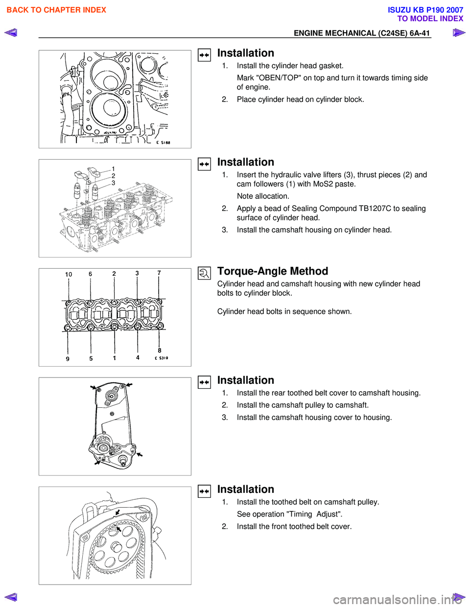
Installation
1. Install the cylinder head gasket.
Mark "OBEN/TOP" on top and turn it towards timing side of engine.
2. Place cylinder head on cylinder block.
1
2
3
Installation
1. Insert the hydraulic valve lifters (3), thrust pieces (2) and
cam followers (1) with MoS2 paste.
Note allocation.
2. Apply a bead of Sealing Compound TB1207C to sealing surface of cylinder head.
3. Install the camshaft housing on cylinder head.
Torque-Angle Method
Cylinder head and camshaft housing with new cylinder head
bolts to cylinder block.
Cylinder head bolts in sequence shown.
Installation
1. Install the rear toothed belt cover to camshaft housing.
2. Install the camshaft pulley to camshaft.
3. Install the camshaft housing cover to housing.
Installation
1. Install the toothed belt on camshaft pulley.
See operation "Timing Adjust".
2. Install the front toothed belt cover.
BACK TO CHAPTER INDEX
TO MODEL INDEX
ISUZU KB P190 2007
Page 2102 of 6020
6A-88 ENGINE MECHANICAL (C24SE)
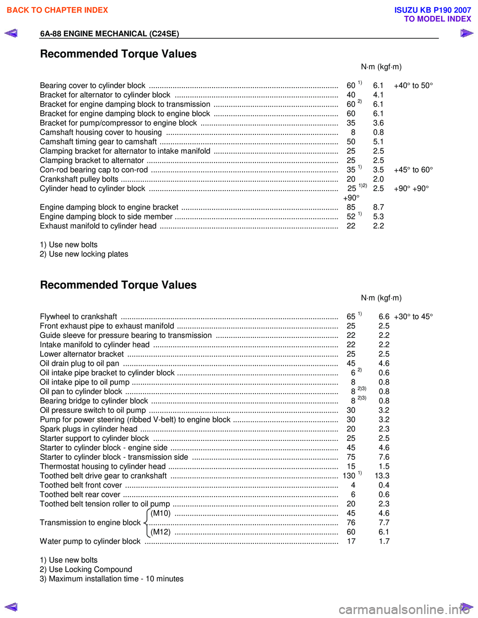
Recommended Torque Values
N⋅m (kgf ⋅m)
Bearing cover to cylinder block ........................................................................................ 60
1) 6.1 +40 ° to 50 °
Bracket for alternator to cylinder block ............................................................................ 40 4.1
Bracket for engine damping block to transmission .......................................................... 60
2) 6.1
Bracket for engine damping block to engine block .......................................................... 60 6.1
Bracket for pump/compressor to engine block ................................................................ 35 3.6
Camshaft housing cover to housing ................................................................................ 8 0.8
Camshaft timing gear to camshaft ................................................................................... 50 5.1
Clamping bracket for alternator to intake manifold .......................................................... 25 2.5
Clamping bracket to alternator ......................................................................................... 25 2.5
Con-rod bearing cap to con-rod ....................................................................................... 35
1) 3.5 +45 ° to 60 °
Crankshaft pulley bolts ..................................................................................................... 2 0 2.0
Cylinder head to cylinder block ........................................................................................ 25
1)2) 2.5 +90 ° +90 °
+90 °
Engine damping block to engine bracket ......................................................................... 85 8.7
Engine damping block to side member ............................................................................ 52
1) 5.3
Exhaust manifold to cylinder head ................................................................................... 22 2.2
1) Use new bolts
2) Use new locking plates
Recommended Torque Values
N⋅m (kgf ⋅m)
Flywheel to crankshaft ..................................................................................................... 65
1) 6.6 +30° to 45 °
Front exhaust pipe to exhaust manifold ........................................................................... 25 2.5
Guide sleeve for pressure bearing to transmission ......................................................... 22 2.2
Intake manifold to cylinder head ...................................................................................... 22 2.2
Lower alternator bracket .................................................................................................. 25 2.5
Oil drain plug to oil pan .................................................................................................... 45 4.6
Oil intake pipe bracket to cylinder block ........................................................................... 6
2) 0.6
Oil intake pipe to oil pump ................................................................................................ 8 0.8
Oil pan to cylinder block ................................................................................................... 8
2)3) 0.8
Bearing bridge to cylinder block ....................................................................................... 8 2)3) 0.8
Oil pressure switch to oil pump ........................................................................................ 30 3.2
Pump for power steering (ribbed V-belt) to engine block ................................................. 30 3.2
Spark plugs in cylinder head ............................................................................................ 20 2. 3
Starter support to cylinder block ...................................................................................... 25 2.5
Starter to cylinder block - engine side .............................................................................. 45 4.6
Starter to cylinder block - transmission side .................................................................... 75 7.6
Thermostat housing to cylinder head ............................................................................... 15 1.5
Toothed belt drive gear to crankshaft .............................................................................. 130
1) 13.3
Toothed belt front cover ................................................................................................... 4 0.4
Toothed belt rear cover .................................................................................................... 6 0.6
Toothed belt tension roller to oil pump ............................................................................. 20 2.3 (M10) ............................................................................ 45 4.6
Transmission to engine block ......................................................................................... 76 7.7 (M12) ............................................................................ 60 6.1
W ater pump to cylinder block .......................................................................................... 17 1.7
1) Use new bolts
2) Use Locking Compound
3) Maximum installation time - 10 minutes
BACK TO CHAPTER INDEX
TO MODEL INDEX
ISUZU KB P190 2007
Page 2107 of 6020
ENGINE COOLING 6B-3
Service Precaution
CAUTION:
Always use the correct fastener in the proper location.
When you replace a fastener, use ONLY the exact part
number for that application. ISUZU will call out those
fasteners that require a replacement after removal. ISUZU
will also call out the fasteners that require thread lockers
or thread sealant. UNLESS OTHERWISE SPECIFIED, do
not use supplemental coatings (Paints, greases, or other
corrosion inhibitors) on threaded fasteners or fastener
joint interfaces. Generally, such coatings adversely affect
the fastener torque and the joint clamping force, and may
damage the fastener. When you install fasteners, use the
correct tightening sequence and specifications. Following
these instructions can help you avoid damage to parts
and systems.
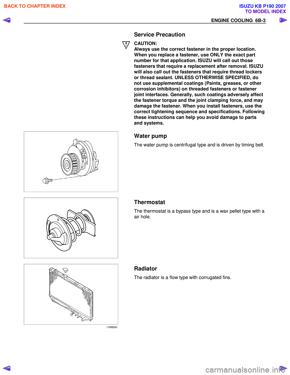
Water pump
The water pump is centrifugal type and is driven by timing belt.
Thermostat
The thermostat is a bypass type and is a wax pellet type with a
air hole.
110RS001
Radiator
The radiator is a flow type with corrugated fins.
BACK TO CHAPTER INDEX
TO MODEL INDEX
ISUZU KB P190 2007
Page 2111 of 6020

ENGINE COOLING 6B-7
Water Pump
Water Pump and Associated Parts
Legend
1 Water Pump Assembly 2 O-Ring
3 Bolt
2
3 1
Removal
1. Disconnect battery ground cable.
2. Drain coolant.
3. Disconnect radiator hose (on inlet pipe side).
4. Remove timing belt, refer to "Timing Belt" in this manual.
5. Remove water pump assembly.
Inspection
Make necessary repair and parts replacement if extreme wear
or damage is found during inspection. Should any of the
following problems occur, the entire water pump assembly
must be replaced:
BACK TO CHAPTER INDEX
TO MODEL INDEX
ISUZU KB P190 2007
Page 2112 of 6020

6B-8 ENGINE COOLING
•
Crack in the water pump body
• EC leakage from the seal unit
• Play or abnormal noise in the bearing
• Cracks or corrosion in the impeller
Installation
1. Before installing water pump, coat sealing surface with
silicon grease.
2. Install water pump assembly and tighten bolts to the specified torque.
Torque: 25 N ⋅
⋅⋅
⋅
m (2.5 kgf ⋅
⋅⋅
⋅
m)
3. Timing belt • Install timing belt, refer to timing belt installation step in
"Timing Belt" in this manual.
4. Connect radiator hose and replenish EC.
5. Connect battery ground cable.
BACK TO CHAPTER INDEX
TO MODEL INDEX
ISUZU KB P190 2007
Page 2411 of 6020

ENGINE DRIVEABILITY AND EMISSIONS 6E–241
17 Perform the procedure in Fuel System Pressure Test(Refer to 6E-108 “Fuel System Diagnosis ”) to
determine if there is a problem with fuel delivery.
Was a problem found? — Verify repair Go to Step 18
18 Check for the following engine mechanical problems (refer to Engine Mechanical ):
• Low compression
• Leaking cylinder head gaskets
• Worn camshaft
• Sticking or leaking valves
• Valve timing
• Broken valve springs
• Camshaft drive belt slipped or stripped
Was a problem found? — Verify repair Go to Step 19
19 1. Review all diagnostic procedures within this table. 2. If all procedures have been completed and nomalfunctions have been found, review/inspect the
following:
• Visual/physical inspection
• Tech 2 data
• All electrical connections within a suspected circuit and/or system
Was a problem found? — Verify repair Go to Step 20
20 Is the ECM programmed with the latest software release?
If not, download the latest software to the ECM using
the “SPS (Service Programming System)”.
Was the problem solved? — Verify repair Go to Step 21
21 Replace the ECM. Is the action complete?
IMPORTANT: The replacement ECM must be
programmed. Refer to section of the Service
Programming System (SPS) in this manual.
Following ECM programming, the immobilizer system
(if equipped) must be linked to the ECM. Refer to
section 11 “Immobilizer System-ECM replacement” for
the ECM/Immobilizer linking procedure. — Verify Repair —
Step
Action Value(s) Yes No
BACK TO CHAPTER INDEX
TO MODEL INDEX
ISUZU KB P190 2007
Page 2420 of 6020

6E–250 ENGINE DRIVEABILITY AND EMISSIONS
19 Check for the following engine mechanical problems(refer to Engine Mechanical ):
• Low compression
• Leaking cylinder head gaskets
• Worn camshaft
• Sticking or leaking valves
• Valve timing
• Broken valve springs
• Camshaft drive belt slipped or stripped
Was a problem found? — Verify repair Go to Step 20
20 1. Check for faulty engine mounts. 2. If a problem is found, repair as necessary.
Was a problem found? — Verify repair Go to Step 21
21 1. Review all diagnostic procedures within this table. 2. If all procedures have been completed and nomalfunctions have been found, review/inspect the
following:
• Visual/physical inspection
• Tech 2 data
• All electrical connections within a suspected circuit and/or system
Was a problem found? — Verify repair Go to Step 22
22 Is the ECM programmed with the latest software release?
If not, download the latest software to the ECM using
the “SPS (Service Programming System)”.
Was the problem solved? — Verify repair Go to Step 23
23 Replace the ECM. Is the action complete?
IMPORTANT: The replacement ECM must be
programmed. Refer to section of the Service
Programming System (SPS) in this manual.
Following ECM programming, the immobilizer system
(if equipped) must be linked to the ECM. Refer to
section 11 “Immobilizer System-ECM replacement” for
the ECM/Immobilizer linking procedure. — Verify Repair —
Step
Action Value(s) Yes No
BACK TO CHAPTER INDEX
TO MODEL INDEX
ISUZU KB P190 2007
Page 2422 of 6020

6E–252 ENGINE DRIVEABILITY AND EMISSIONS
12 Monitor “B1S1 (Bank 1 Sensor 1) Status ” on the Tech
2.
Is the “ B1S1 (Bank 1 Sensor 1) Status ” in the rich
condition? — Verify repair Go to Step 13
13 Check items that can cause the engine to run rich. Refer to DTC P1167 “Fuel Supply System Rich During
Deceleration Fuel Cut Off”.
Was a problem found? — Verify repair Go to Step 14
14 Check items that can cause the engine to run lean. Refer to DTC P1171 “Fuel Supply System Lean
During Power Enrichment”.
Was a problem found? — Verify repair Go to Step 15
15 Check for proper ignition voltage output with a spark tester.
Was the problem found? — Verify repair Go to Step 16
16 1. Remove the spark plugs and check for gas or oil fouling cracks, wear, improper gap, burned
electrodes, heavy deposits, or improper heat
range.
2. If spark plugs are fouled, the cause of fouling must be determined before replacing the spark plugs.
Was a problem found? — Verify repair Go to Step 17
17 Drain sample fuel, visual inspection. Any suspecion about the fuel, such as discoloration,
particle, contamination, water, unusual smell, then
drain the fuel from fuel tank.
Replace the fuel from know vehicle source.
If any suspencion of alcohol contamination,
completely drain the fuel, replace by fuel from known
vehicle source. — Verify repair Go to Step 18
18 Check the exhaust system for a possible restriction: • Damaged or collapsed pipes
• Internal muffler failure
Was a problem found? — Verify repair Go to Step 19
19 Check for the following engine mechanical problems (refer to Engine Mechanical ):
• Low compression
• Leaking cylinder head gaskets
• Worn camshaft
• Loose timing belt
Was a problem found? — Verify repair Go to Step 20
20 1. Review all diagnostic procedures within this table. 2. If all procedures have been completed and nomalfunctions have been found, review/inspect the
following:
• Visual/physical inspection
• Tech 2 data
• All electrical connections within a suspected circuit and/or system
Was a problem found? — Verify repair Go to Step 21
Step
Action Value(s) Yes No
BACK TO CHAPTER INDEX
TO MODEL INDEX
ISUZU KB P190 2007