tire size ISUZU KB P190 2007 Workshop Repair Manual
[x] Cancel search | Manufacturer: ISUZU, Model Year: 2007, Model line: KB P190, Model: ISUZU KB P190 2007Pages: 6020, PDF Size: 70.23 MB
Page 406 of 6020
3E-2 WHEELS AND TIRES
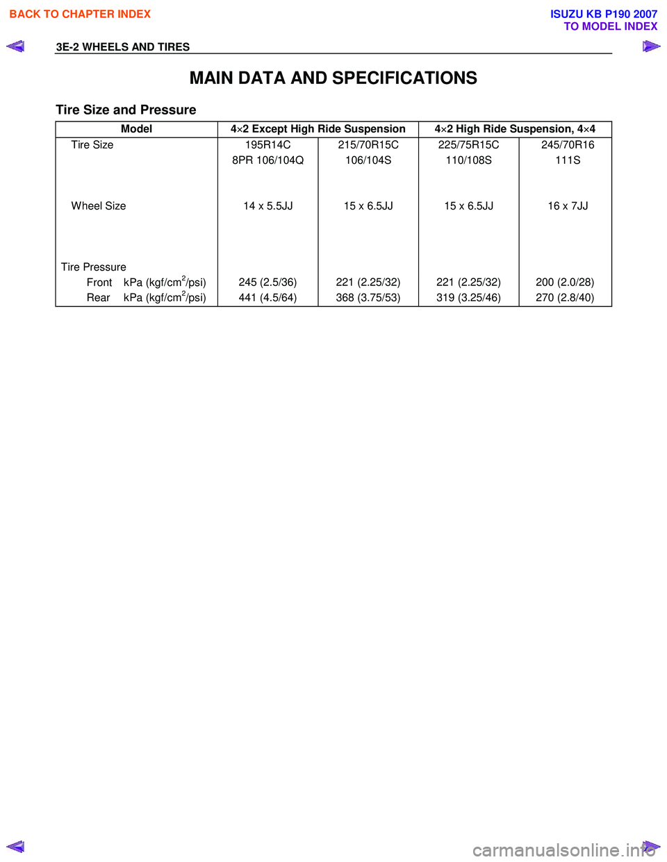
MAIN DATA AND SPECIFICATIONS
Tire Size and Pressure
Model 4×
××
×
2 Except High Ride Suspension 4×
××
×
2 High Ride Suspension, 4 ×
××
×
4
Tire Size
W heel Size
195R14C
8PR 106/104Q
14 x 5.5JJ
215/70R15C
106/104S
15 x 6.5JJ
225/75R15C
110/108S
15 x 6.5JJ
245/70R16
111S
16 x 7JJ
Tire Pressure
Front kPa (kgf/cm2/psi)
Rear kPa (kgf/cm2/psi) 245 (2.5/36)
441 (4.5/64) 221 (2.25/32)
368 (3.75/53) 221 (2.25/32)
319 (3.25/46) 200 (2.0/28)
270 (2.8/40)
BACK TO CHAPTER INDEX
TO MODEL INDEX
ISUZU KB P190 2007
Page 409 of 6020
WHEELS AND TIRES 3E-5
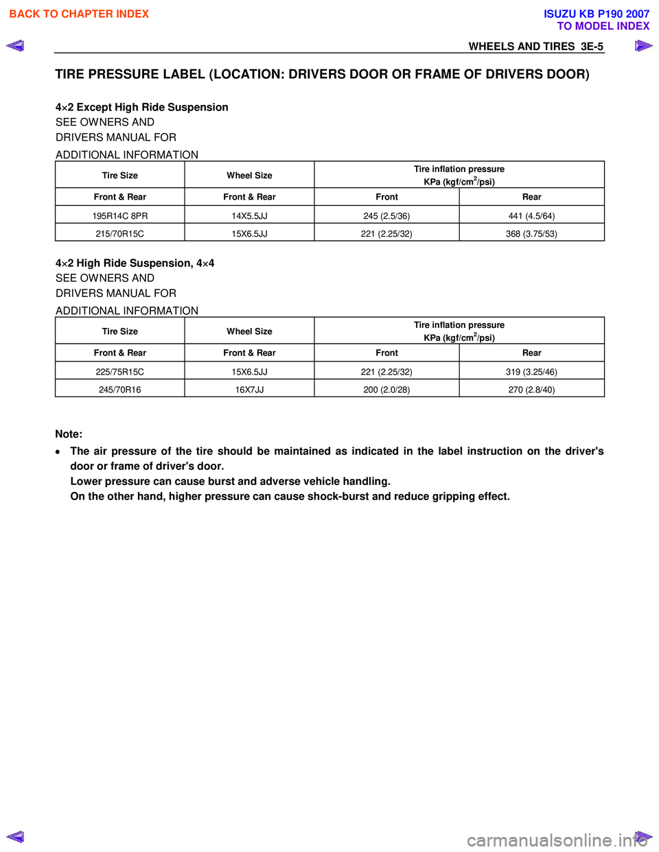
TIRE PRESSURE LABEL (LOCATION: DRIVERS DOOR OR FRAME OF DRIVERS DOOR)
4 ×
××
×
2 Except High Ride Suspension
SEE OW NERS AND
DRIVERS MANUAL FOR
ADDITIONAL INFORMATION
Tire Size Wheel Size Tire inflation pressure
KPa (kgf/cm
2/psi)
Front & Rear Front & Rear Front Rear
195R14C 8PR 14X5.5JJ 245 (2.5/36) 441 (4.5/64)
215/70R15C 15X6.5JJ 221 (2.25/32) 368 (3.75/53)
4 ×
××
×
2 High Ride Suspension, 4 ×
××
×
4
SEE OW NERS AND
DRIVERS MANUAL FOR
ADDITIONAL INFORMATION
Tire Size Wheel Size Tire inflation pressure
KPa (kgf/cm
2/psi)
Front & Rear Front & Rear Front Rear
225/75R15C 15X6.5JJ 221 (2.25/32) 319 (3.25/46)
245/70R16 16X7JJ 200 (2.0/28) 270 (2.8/40)
Note:
•
••
•
The air pressure of the tire should be maintained as indicated in the label instruction on the driver's
door or frame of driver's door.
Lower pressure can cause burst and adverse vehicle handling.
On the other hand, higher pressure can cause shock-burst and reduce gripping effect.
BACK TO CHAPTER INDEX
TO MODEL INDEX
ISUZU KB P190 2007
Page 657 of 6020
5A-64 BRAKE CONTROL SYSTEM
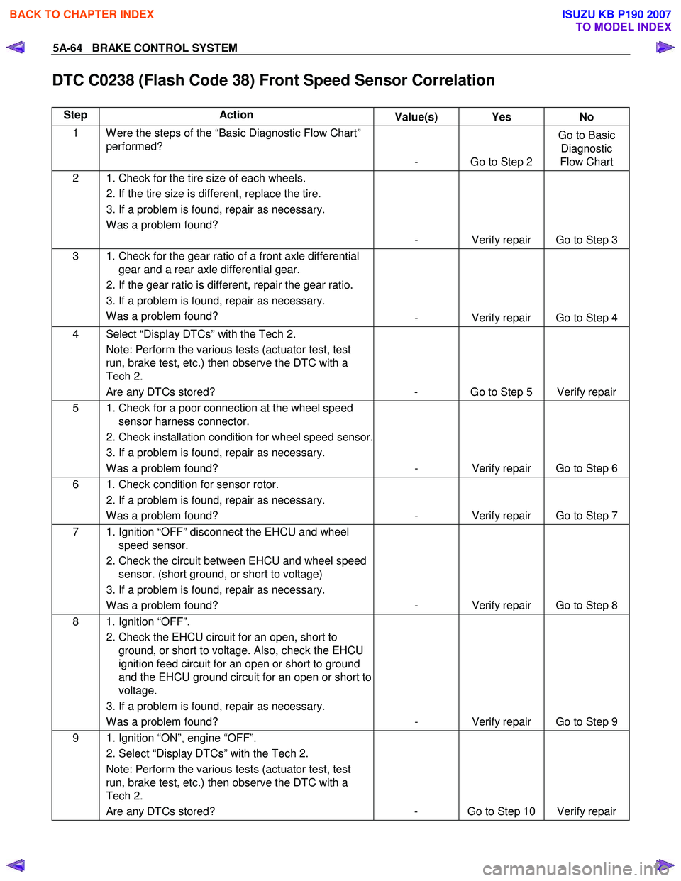
DTC C0238 (Flash Code 38) Front Speed Sensor Correlation
Step Action Value(s) Yes No
1 W ere the steps of the “Basic Diagnostic Flow Chart”
performed?
- Go to Step 2 Go to Basic
Diagnostic
Flow Chart
2 1. Check for the tire size of each wheels.
2. If the tire size is different, replace the tire.
3. If a problem is found, repair as necessary. W as a problem found? - Verify repair Go to Step 3
3 1. Check for the gear ratio of a front axle differential gear and a rear axle differential gear.
2. If the gear ratio is different, repair the gear ratio.
3. If a problem is found, repair as necessary. W as a problem found? - Verify repair Go to Step 4
4 Select “Display DTCs” with the Tech 2.
Note: Perform the various tests (actuator test, test
run, brake test, etc.) then observe the DTC with a
Tech 2.
Are any DTCs stored? - Go to Step 5 Verify repair
5 1. Check for a poor connection at the wheel speed sensor harness connector.
2. Check installation condition for wheel speed sensor.
3. If a problem is found, repair as necessary. W as a problem found? - Verify repair Go to Step 6
6 1. Check condition for sensor rotor.
2. If a problem is found, repair as necessary. W as a problem found? - Verify repair Go to Step 7
7 1. Ignition “OFF” disconnect the EHCU and wheel
speed sensor.
2. Check the circuit between EHCU and wheel speed sensor. (short ground, or short to voltage)
3. If a problem is found, repair as necessary. W as a problem found? - Verify repair Go to Step 8
8 1. Ignition “OFF”.
2. Check the EHCU circuit for an open, short to ground, or short to voltage. Also, check the EHCU
ignition feed circuit for an open or short to ground
and the EHCU ground circuit for an open or short to
voltage.
3. If a problem is found, repair as necessary. W as a problem found? - Verify repair Go to Step 9
9 1. Ignition “ON”, engine “OFF”.
2. Select “Display DTCs” with the Tech 2. Note: Perform the various tests (actuator test, test
run, brake test, etc.) then observe the DTC with a
Tech 2.
Are any DTCs stored? - Go to Step 10 Verify repair
BACK TO CHAPTER INDEX
TO MODEL INDEX
ISUZU KB P190 2007
Page 726 of 6020
BRAKES 5C-27
15. Repeat steps 12 through 14 until no air comes out of the
port when the brake pipe is loosened
NOTE: Be very careful not to allow the brake fluid to come in contact with painted surfaces.
RTW 75CSH001801
16. Bleed the air from the front wheel brake pipe connection (2)
by repeating steps 6 through 15.
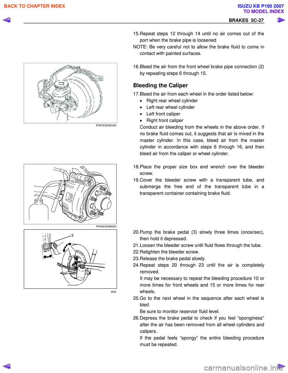
Bleeding the Caliper
17. Bleed the air from each wheel in the order listed below: • Right rear wheel cylinder
• Left rear wheel cylinder
• Left front caliper
• Right front caliper
Conduct air bleeding from the wheels in the above order. I
f
no brake fluid comes out, it suggests that air is mixed in the
master cylinder. In this case, bleed air from the maste
r
cylinder in accordance with steps 6 through 16, and then
bleed air from the caliper or wheel cylinder.
RTW 35CSH000501
18. Place the proper size box end wrench over the bleeder
screw.
19. Cover the bleeder screw with a transparent tube, and submerge the free end of the transparent tube in a
transparent container containing brake fluid.
3
5042
20. Pump the brake pedal (3) slowly three times (once/sec),
then hold it depressed.
21. Loosen the bleeder screw until fluid flows through the tube.
22. Retighten the bleeder screw.
23. Release the brake pedal slowly.
24. Repeat steps 20 through 23 until the air is completel
y
removed.
It may be necessary to repeat the bleeding procedure 10 o
r
more times for front wheels and 15 or more times for rear
wheels.
25. Go to the next wheel in the sequence after each wheel is bled.
Be sure to monitor reservoir fluid level.
26. Depress the brake pedal to check if you feel “sponginess” after the air has been removed from all wheel cylinders and
calipers.
If the pedal feels “spongy” the entire bleeding procedure must be repeated.
BACK TO CHAPTER INDEX
TO MODEL INDEX
ISUZU KB P190 2007
Page 1300 of 6020
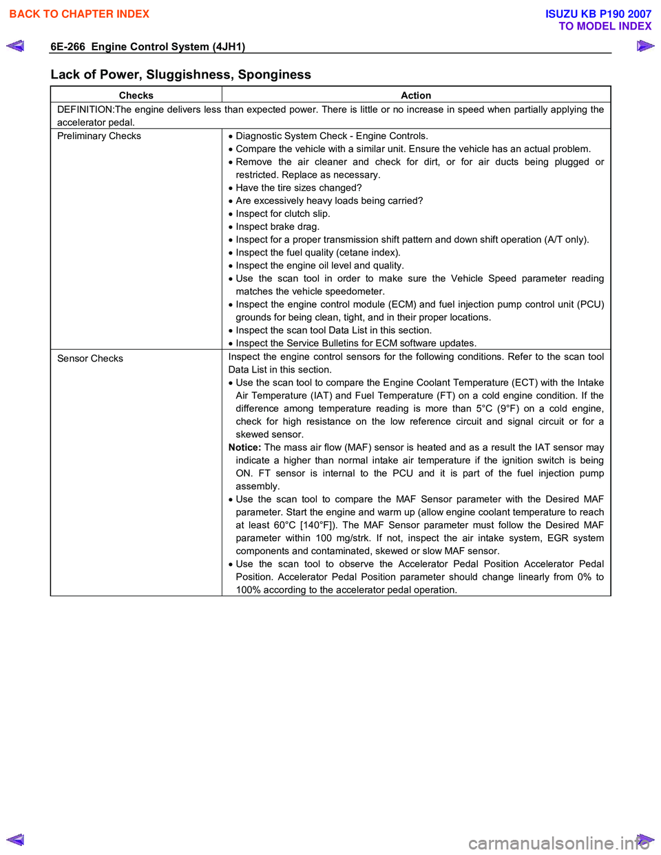
6E-266 Engine Control System (4JH1)
Lack of Power, Sluggishness, Sponginess
Checks Action
DEFINITION:The engine delivers less than expected power. There is little or no increase in speed when partially applying the
accelerator pedal.
Preliminary Checks • Diagnostic System Check - Engine Controls.
• Compare the vehicle with a similar unit. Ensure the vehicle has an actual problem.
• Remove the air cleaner and check for dirt, or for air ducts being plugged or
restricted. Replace as necessary.
• Have the tire sizes changed?
• Are excessively heavy loads being carried?
• Inspect for clutch slip.
• Inspect brake drag.
• Inspect for a proper transmission shift pattern and down shift operation (A/T only).
• Inspect the fuel quality (cetane index).
• Inspect the engine oil level and quality.
• Use the scan tool in order to make sure the Vehicle Speed parameter reading
matches the vehicle speedometer.
• Inspect the engine control module (ECM) and fuel injection pump control unit (PCU)
grounds for being clean, tight, and in their proper locations.
• Inspect the scan tool Data List in this section.
• Inspect the Service Bulletins for ECM software updates.
Sensor Checks Inspect the engine control sensors for the following conditions. Refer to the scan tool
Data List in this section.
• Use the scan tool to compare the Engine Coolant Temperature (ECT) with the Intake
Air Temperature (IAT) and Fuel Temperature (FT) on a cold engine condition. If the
difference among temperature reading is more than 5°C (9°F) on a cold engine,
check for high resistance on the low reference circuit and signal circuit or for a
skewed sensor.
Notice: The mass air flow (MAF) sensor is heated and as a result the IAT sensor may
indicate a higher than normal intake air temperature if the ignition switch is being
ON. FT sensor is internal to the PCU and it is part of the fuel injection pump
assembly.
• Use the scan tool to compare the MAF Sensor parameter with the Desired MAF
parameter. Start the engine and warm up (allow engine coolant temperature to reach
at least 60°C [140°F]). The MAF Sensor parameter must follow the Desired MAF
parameter within 100 mg/strk. If not, inspect the air intake system, EGR system
components and contaminated, skewed or slow MAF sensor.
• Use the scan tool to observe the Accelerator Pedal Position Accelerator Pedal
Position. Accelerator Pedal Position parameter should change linearly from 0% to
100% according to the accelerator pedal operation.
BACK TO CHAPTER INDEX
TO MODEL INDEX
ISUZU KB P190 2007
Page 1305 of 6020
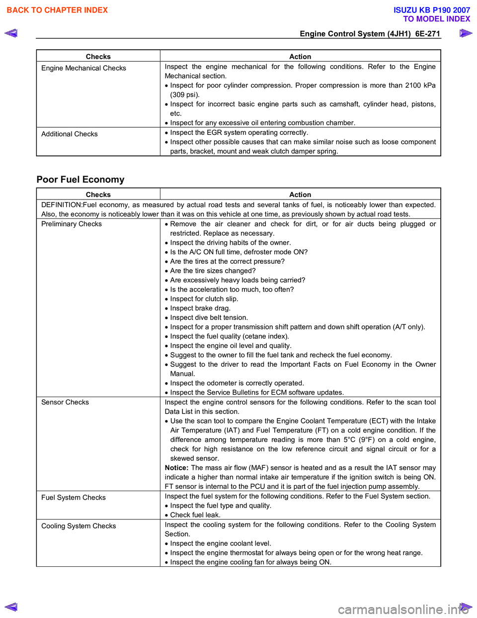
Engine Control System (4JH1) 6E-271
Checks Action
Engine Mechanical Checks Inspect the engine mechanical for the following conditions. Refer to the Engine
Mechanical section.
• Inspect for poor cylinder compression. Proper compression is more than 2100 kPa
(309 psi).
• Inspect for incorrect basic engine parts such as camshaft, cylinder head, pistons,
etc.
• Inspect for any excessive oil entering combustion chamber.
Additional Checks •
Inspect the EGR system operating correctly.
• Inspect other possible causes that can make similar noise such as loose component
parts, bracket, mount and weak clutch damper spring.
Poor Fuel Economy
Checks Action
DEFINITION:Fuel economy, as measured by actual road tests and several tanks of fuel, is noticeably lower than expected.
Also, the economy is noticeably lower than it was on this vehicle at one time, as previously shown by actual road tests.
Preliminary Checks • Remove the air cleaner and check for dirt, or for air ducts being plugged or
restricted. Replace as necessary.
• Inspect the driving habits of the owner.
• Is the A/C ON full time, defroster mode ON?
• Are the tires at the correct pressure?
• Are the tire sizes changed?
• Are excessively heavy loads being carried?
• Is the acceleration too much, too often?
• Inspect for clutch slip.
• Inspect brake drag.
• Inspect dive belt tension.
• Inspect for a proper transmission shift pattern and down shift operation (A/T only).
• Inspect the fuel quality (cetane index).
• Inspect the engine oil level and quality.
• Suggest to the owner to fill the fuel tank and recheck the fuel economy.
• Suggest to the driver to read the Important Facts on Fuel Economy in the Owner
Manual.
• Inspect the odometer is correctly operated.
• Inspect the Service Bulletins for ECM software updates.
Sensor Checks Inspect the engine control sensors for the following conditions. Refer to the scan tool
Data List in this section.
• Use the scan tool to compare the Engine Coolant Temperature (ECT) with the Intake
Air Temperature (IAT) and Fuel Temperature (FT) on a cold engine condition. If the
difference among temperature reading is more than 5°C (9°F) on a cold engine,
check for high resistance on the low reference circuit and signal circuit or for a
skewed sensor.
Notice: The mass air flow (MAF) sensor is heated and as a result the IAT sensor may
indicate a higher than normal intake air temperature if the ignition switch is being ON.
FT sensor is internal to the PCU and it is part of the fuel injection pump assembly.
Fuel System Checks Inspect the fuel system for the following conditions. Refer to the Fuel System section.
• Inspect the fuel type and quality.
• Check fuel leak.
Cooling System Checks Inspect the cooling system for the following conditions. Refer to the Cooling System
Section.
• Inspect the engine coolant level.
• Inspect the engine thermostat for always being open or for the wrong heat range.
• Inspect the engine cooling fan for always being ON.
BACK TO CHAPTER INDEX
TO MODEL INDEX
ISUZU KB P190 2007
Page 1953 of 6020
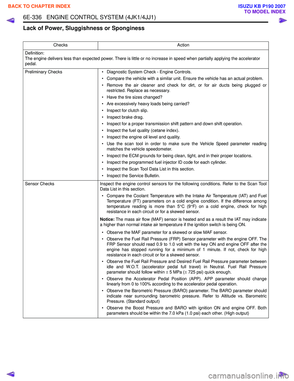
6E-336 ENGINE CONTROL SYSTEM (4JK1/4JJ1)
Lack of Power, Sluggishness or Sponginess
ChecksAction
Definition:
The engine delivers less than expected power. There is little or no increase in speed when partially applying the accelerator
pedal.
Preliminary Checks • Diagnostic System Check - Engine Controls.
• Compare the vehicle with a similar unit. Ensure the vehicle has an actual problem.
• Remove the air cleaner and check for dirt, or for air ducts being plugged or restricted. Replace as necessary.
• Have the tire sizes changed?
• Are excessively heavy loads being carried?
• Inspect for clutch slip.
• Inspect brake drag.
• Inspect for a proper transmission shift pattern and down shift operation.
• Inspect the fuel quality (cetane index).
• Inspect the engine oil level and quality.
• Use the scan tool in order to make sure the Vehicle Speed parameter reading matches the vehicle speedometer.
• Inspect the ECM grounds for being clean, tight, and in their proper locations.
• Inspect the programmed fuel injector ID code for each cylinder.
• Inspect the Scan Tool Data List in this section.
• Inspect the Service Bulletin.
Sensor Checks Inspect the engine control sensors for the following conditions. Refer to the Scan Tool
Data List in this section.
• Compare the Coolant Temperature with the Intake Air Temperature (IAT) and Fuel Temperature (FT) parameters on a cold engine condition. If the difference among
temperature reading is more than 5 °C (9 °F) on a cold engine, check for high
resistance in each circuit or for a skewed sensor.
Notice: The mass air flow (MAF) sensor is heated and as a result the IAT may indicate
a higher than normal intake air temperature if the ignition switch is being ON.
• Observe the MAF parameter for a skewed or slow MAF sensor.
• Observe the Fuel Rail Pressure (FRP) Sensor parameter with the engine OFF. The FRP Sensor should read 0.9 to 1.0 volt with the key ON and engine OFF after the
engine has stopped running for a minimum of 1 minute. If not, check for high
resistance in each circuit or for a skewed sensor.
• Observe the Fuel Rail Pressure and Desired Fuel Rail Pressure parameter between idle and W.O.T. (accelerator pedal full travel) in Neutral. Fuel Rail Pressure
parameter should follow within ± 5 MPa ( ± 725 psi) quick enough.
• Observe the Accelerator Pedal Position (APP). APP parameter should change linearly from 0 to 100% according to the accelerator pedal operation.
• Observe the Barometric Pressure (BARO) parameter. The BARO parameter should indicate near surrounding barometric pressure. Refer to Altitude vs. Barometric
Pressure. (Standard output)
• Observe the Boost Pressure and BARO with ignition ON and engine OFF. Both parameters should be within the 7.0 kPa (1.0 psi) each other. (High output)
BACK TO CHAPTER INDEX
TO MODEL INDEX
ISUZU KB P190 2007
Page 1958 of 6020
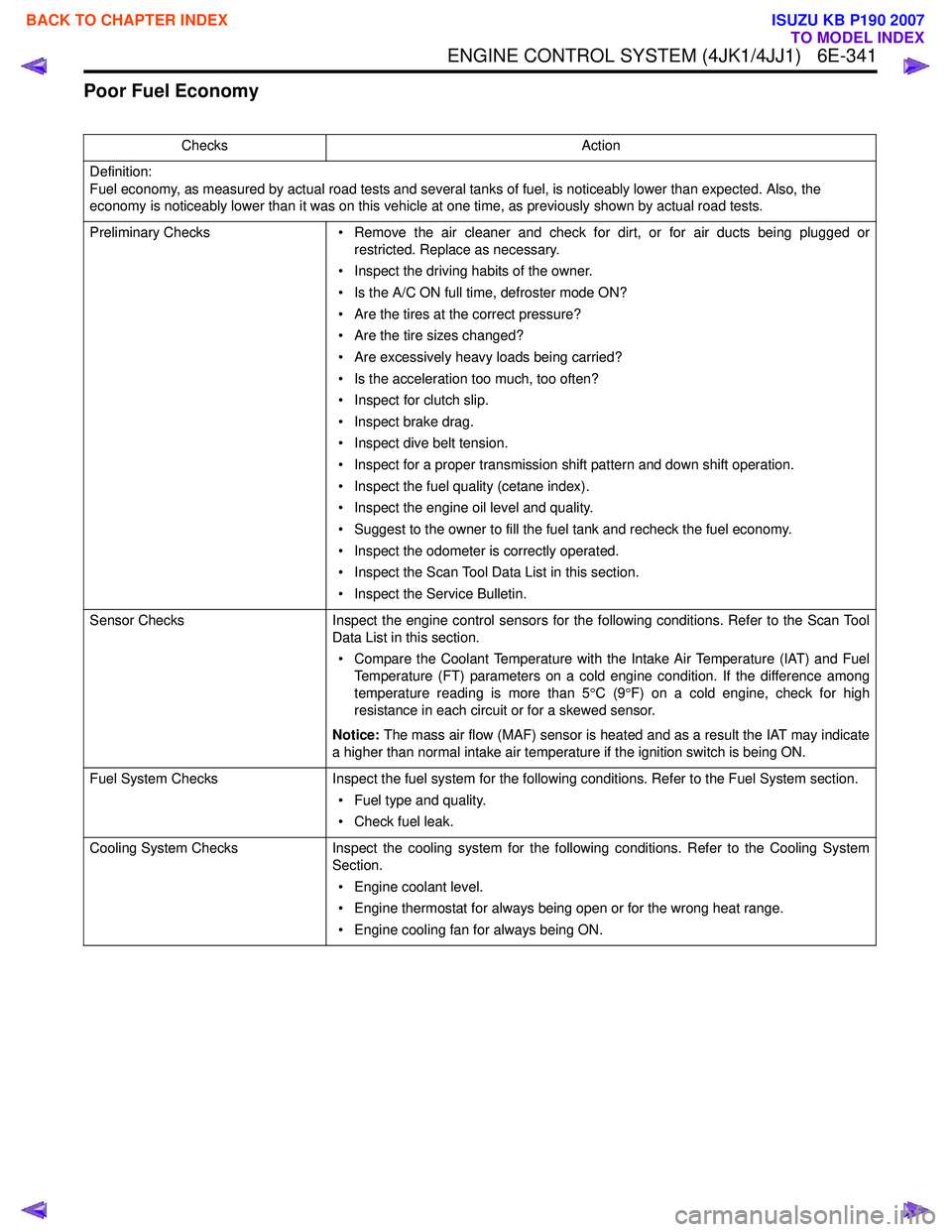
ENGINE CONTROL SYSTEM (4JK1/4JJ1) 6E-341
Poor Fuel Economy
ChecksAction
Definition:
Fuel economy, as measured by actual road tests and several tanks of fuel, is noticeably lower than expected. Also, the
economy is noticeably lower than it was on this vehicle at one time, as previously shown by actual road tests.
Preliminary Checks • Remove the air cleaner and check for dirt, or for air ducts being plugged or
restricted. Replace as necessary.
• Inspect the driving habits of the owner.
• Is the A/C ON full time, defroster mode ON?
• Are the tires at the correct pressure?
• Are the tire sizes changed?
• Are excessively heavy loads being carried?
• Is the acceleration too much, too often?
• Inspect for clutch slip.
• Inspect brake drag.
• Inspect dive belt tension.
• Inspect for a proper transmission shift pattern and down shift operation.
• Inspect the fuel quality (cetane index).
• Inspect the engine oil level and quality.
• Suggest to the owner to fill the fuel tank and recheck the fuel economy.
• Inspect the odometer is correctly operated.
• Inspect the Scan Tool Data List in this section.
• Inspect the Service Bulletin.
Sensor Checks Inspect the engine control sensors for the following conditions. Refer to the Scan Tool
Data List in this section.
• Compare the Coolant Temperature with the Intake Air Temperature (IAT) and Fuel Temperature (FT) parameters on a cold engine condition. If the difference among
temperature reading is more than 5 °C (9 °F) on a cold engine, check for high
resistance in each circuit or for a skewed sensor.
Notice: The mass air flow (MAF) sensor is heated and as a result the IAT may indicate
a higher than normal intake air temperature if the ignition switch is being ON.
Fuel System Checks Inspect the fuel system for the following conditions. Refer to the Fuel System section.
• Fuel type and quality.
• Check fuel leak.
Cooling System Checks Inspect the cooling system for the following conditions. Refer to the Cooling System
Section.
• Engine coolant level.
• Engine thermostat for always being open or for the wrong heat range.
• Engine cooling fan for always being ON.
BACK TO CHAPTER INDEX
TO MODEL INDEX
ISUZU KB P190 2007
Page 2008 of 6020
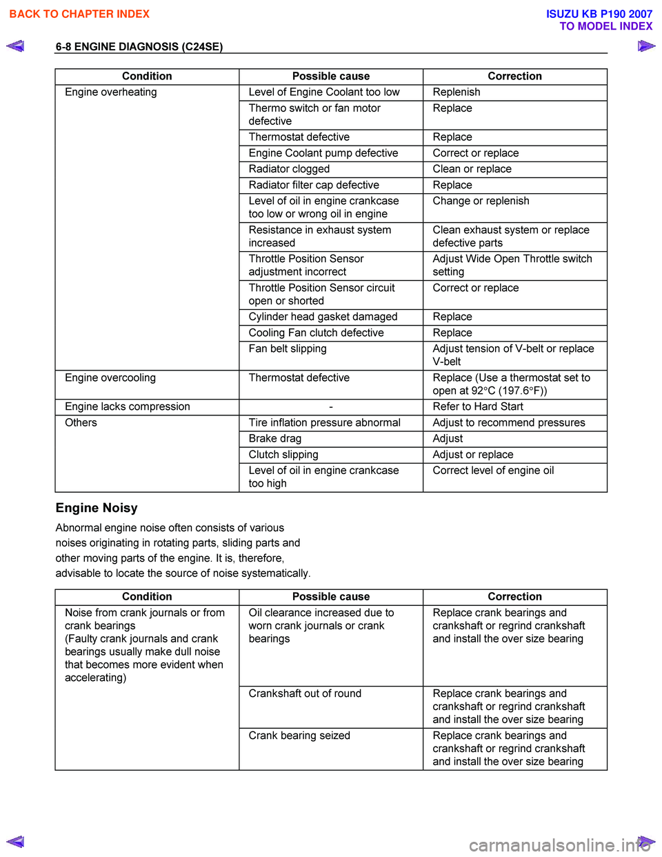
6-8 ENGINE DIAGNOSIS (C24SE)
Condition Possible cause Correction
Engine overheating Level of Engine Coolant too low Replenish
Thermo switch or fan motor
defective Replace
Thermostat
defective Replace
Engine Coolant pump defective Correct or replace
Radiator clogged Clean or replace
Radiator filter cap defective Replace
Level of oil in engine crankcase
too low or wrong oil in engine Change or replenish
Resistance in exhaust system
increased Clean exhaust system or replace
defective parts
Throttle Position Sensor
adjustment incorrect Adjust Wide Open Throttle switch
setting
Throttle Position Sensor circuit
open or shorted Correct or replace
Cylinder head gasket damaged Replace
Cooling Fan clutch defective Replace
Fan belt slipping Adjust tension of V-belt or replace
V-belt
Engine overcooling Thermostat defective Replace (Use a thermostat set to
open at 92 °C (197.6 °F))
Engine lacks compression - Refer to Hard Start
Others Tire inflation pressure abnormal Adjust to recommend pressures
Brake drag Adjust
Clutch slipping Adjust or replace
Level of oil in engine crankcase
too high Correct level of engine oil
Engine Noisy
Abnormal engine noise often consists of various
noises originating in rotating parts, sliding parts and
other moving parts of the engine. It is, therefore,
advisable to locate the source of noise systematically.
Condition Possible cause Correction
Noise from crank journals or from
crank bearings
(Faulty crank journals and crank
bearings usually make dull noise
that becomes more evident when
accelerating) Oil clearance increased due to
worn crank journals or crank
bearings Replace crank bearings and
crankshaft or regrind crankshaft
and install the over size bearing
Crankshaft out of round Replace crank bearings and
crankshaft or regrind crankshaft
and install the over size bearing
Crank bearing seized Replace crank bearings and
crankshaft or regrind crankshaft
and install the over size bearing
BACK TO CHAPTER INDEX
TO MODEL INDEX
ISUZU KB P190 2007
Page 2519 of 6020
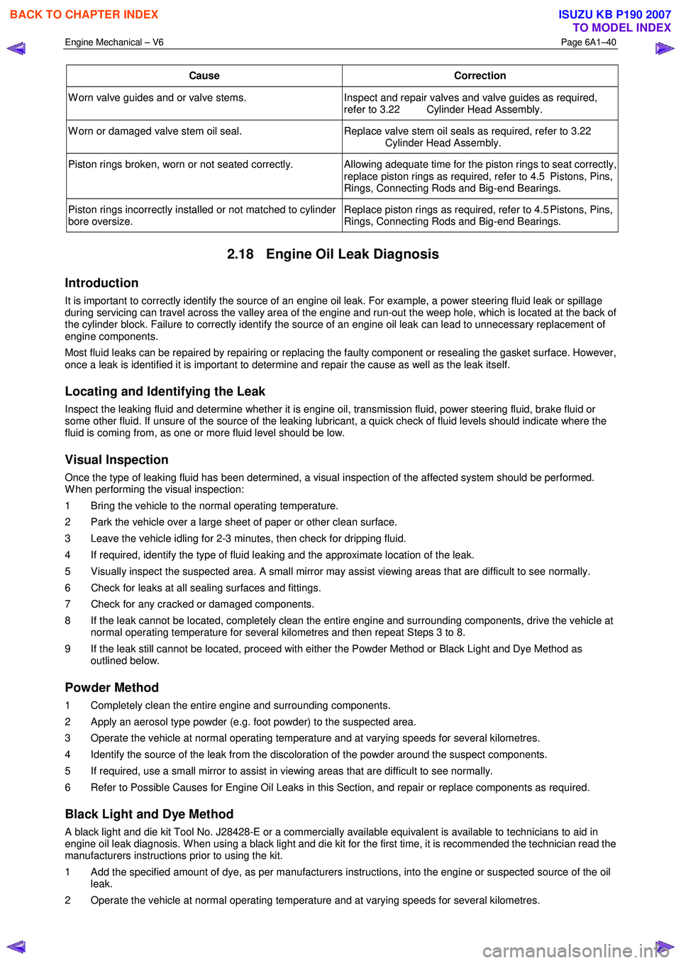
Engine Mechanical – V6 Page 6A1–40
Cause Correction
W orn valve guides and or valve stems. Inspect and repair valves and valve guides as required,
refer to 3.22 Cylinder Head Assembly.
W orn or damaged valve stem oil seal. Replace valve stem oil seals as required, refer to 3.22
Cylinder Head Assembly.
Piston rings broken, worn or not seated correctly. Allowing adequate time for the piston rings to seat correctly,
replace piston rings as required, refer to 4.5 Pistons, Pins,
Rings, Connecting Rods and Big-end Bearings.
Piston rings incorrectly installed or not matched to cylinder
bore oversize. Replace piston rings as required, refer to 4.5 Pistons, Pins,
Rings, Connecting Rods and Big-end Bearings.
2.18 Engine Oil Leak Diagnosis
Introduction
It is important to correctly identify the source of an engine oil leak. For example, a power steering fluid leak or spillage
during servicing can travel across the valley area of the engine and run-out the weep hole, which is located at the back of
the cylinder block. Failure to correctly identify the source of an engine oil leak can lead to unnecessary replacement of
engine components.
Most fluid leaks can be repaired by repairing or replacing the faulty component or resealing the gasket surface. However,
once a leak is identified it is important to determine and repair the cause as well as the leak itself.
Locating and Identifying the Leak
Inspect the leaking fluid and determine whether it is engine oil, transmission fluid, power steering fluid, brake fluid or
some other fluid. If unsure of the source of the leaking lubricant, a quick check of fluid levels should indicate where the
fluid is coming from, as one or more fluid level should be low.
Visual Inspection
Once the type of leaking fluid has been determined, a visual inspection of the affected system should be performed.
W hen performing the visual inspection:
1 Bring the vehicle to the normal operating temperature.
2 Park the vehicle over a large sheet of paper or other clean surface.
3 Leave the vehicle idling for 2-3 minutes, then check for dripping fluid.
4 If required, identify the type of fluid leaking and the approximate location of the leak.
5 Visually inspect the suspected area. A small mirror may assist viewing areas that are difficult to see normally.
6 Check for leaks at all sealing surfaces and fittings.
7 Check for any cracked or damaged components.
8 If the leak cannot be located, completely clean the entire engine and surrounding components, drive the vehicle at normal operating temperature for several kilometres and then repeat Steps 3 to 8.
9 If the leak still cannot be located, proceed with either the Powder Method or Black Light and Dye Method as outlined below.
Powder Method
1 Completely clean the entire engine and surrounding components.
2 Apply an aerosol type powder (e.g. foot powder) to the suspected area.
3 Operate the vehicle at normal operating temperature and at varying speeds for several kilometres.
4 Identify the source of the leak from the discoloration of the powder around the suspect components.
5 If required, use a small mirror to assist in viewing areas that are difficult to see normally.
6 Refer to Possible Causes for Engine Oil Leaks in this Section, and repair or replace components as required.
Black Light and Dye Method
A black light and die kit Tool No. J28428-E or a commercially available equivalent is available to technicians to aid in
engine oil leak diagnosis. W hen using a black light and die kit for the first time, it is recommended the technician read the
manufacturers instructions prior to using the kit.
1 Add the specified amount of dye, as per manufacturers instructions, into the engine or suspected source of the oil leak.
2 Operate the vehicle at normal operating temperature and at varying speeds for several kilometres.
BACK TO CHAPTER INDEX
TO MODEL INDEX
ISUZU KB P190 2007