boot ISUZU KB P190 2007 Workshop Owner's Manual
[x] Cancel search | Manufacturer: ISUZU, Model Year: 2007, Model line: KB P190, Model: ISUZU KB P190 2007Pages: 6020, PDF Size: 70.23 MB
Page 520 of 6020
4C1-16 FRONT WHEEL DRIVE
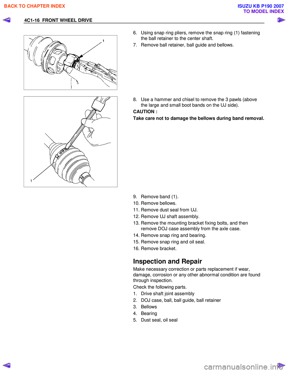
6. Using snap ring pliers, remove the snap ring (1) fastening
the ball retainer to the center shaft.
7. Remove ball retainer, ball guide and bellows.
8. Use a hammer and chisel to remove the 3 pawls (above
the large and small boot bands on the UJ side).
CAUTION :
Take care not to damage the bellows during band removal.
9. Remove band (1).
10. Remove bellows.
11. Remove dust seal from UJ.
12. Remove UJ shaft assembly.
13. Remove the mounting bracket fixing bolts, and then remove DOJ case assembly from the axle case.
14. Remove snap ring and bearing.
15. Remove snap ring and oil seal.
16. Remove bracket.
Inspection and Repair
Make necessary correction or parts replacement if wear,
damage, corrosion or any other abnormal condition are found
through inspection.
Check the following parts.
1. Drive shaft joint assembly
2. DOJ case, ball, ball guide, ball retainer
3. Bellows
4. Bearing
5. Dust seal, oil seal
BACK TO CHAPTER INDEX
TO MODEL INDEX
ISUZU KB P190 2007
Page 732 of 6020
BRAKES 5C-33
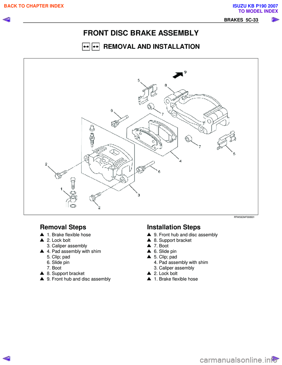
FRONT DISC BRAKE ASSEMBLY
REMOVAL AND INSTALLATION
RTW 55CMF000501
Removal Steps
1. Brake flexible hose
2. Lock bolt
3. Caliper assembly
4. Pad assembly with shim
5. Clip; pad
6. Slide pin
7. Boot
8. Support bracket
9. Front hub and disc assembly
Installation Steps
9. Front hub and disc assembly
8. Support bracket
7. Boot
6. Slide pin
5. Clip; pad
4. Pad assembly with shim
3. Caliper assembly
2. Lock bolt
1. Brake flexible hose
BACK TO CHAPTER INDEX
TO MODEL INDEX
ISUZU KB P190 2007
Page 734 of 6020
BRAKES 5C-35
9. Front Hub and Disc Assembly
For the removal procedure, refer to Section 4C “FRONT
W HEEL DRIVE”.
Important Operations - Installation
9. Front Hub and Disc Assembly
For the installation procedure, refer to the front hub and disc
reassembly procedure in Section 4C “FRONT W HEEL
DRIVE”.
RUW 55CSH000101
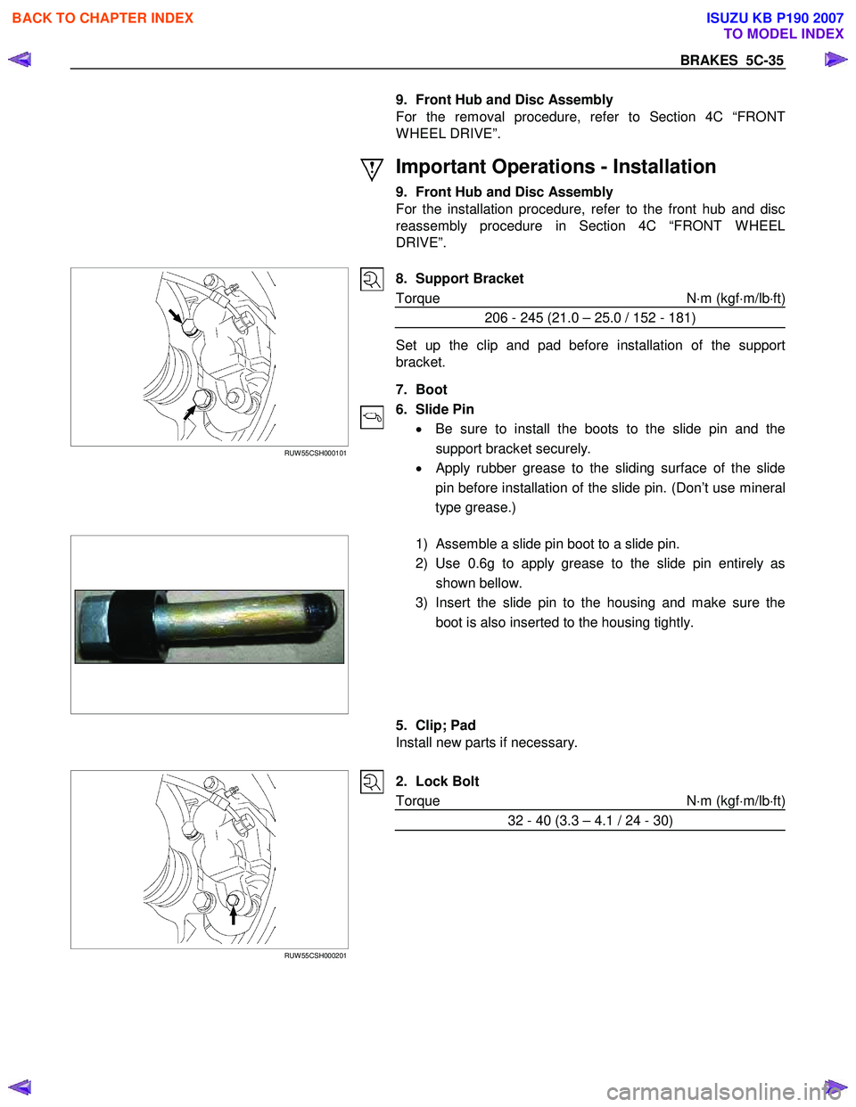
8. Support Bracket
Torque N ⋅m (kgf ⋅m/lb ⋅ft)
206 - 245 (21.0 – 25.0 / 152 - 181)
Set up the clip and pad before installation of the support
bracket.
7. Boot
6. Slide Pin • Be sure to install the boots to the slide pin and the
support bracket securely.
•
Apply rubber grease to the sliding surface of the slide
pin before installation of the slide pin. (Don’t use mineral
type grease.)
1) Assemble a slide pin boot to a slide pin.
2) Use 0.6g to apply grease to the slide pin entirely as shown bellow.
3) Insert the slide pin to the housing and make sure the boot is also inserted to the housing tightly.
5. Clip; Pad
Install new parts if necessary.
RUW 55CSH000201
2. Lock Bolt
Torque N ⋅m (kgf ⋅m/lb ⋅ft)
32 - 40 (3.3 – 4.1 / 24 - 30)
BACK TO CHAPTER INDEX
TO MODEL INDEX
ISUZU KB P190 2007
Page 740 of 6020
BRAKES 5C-41
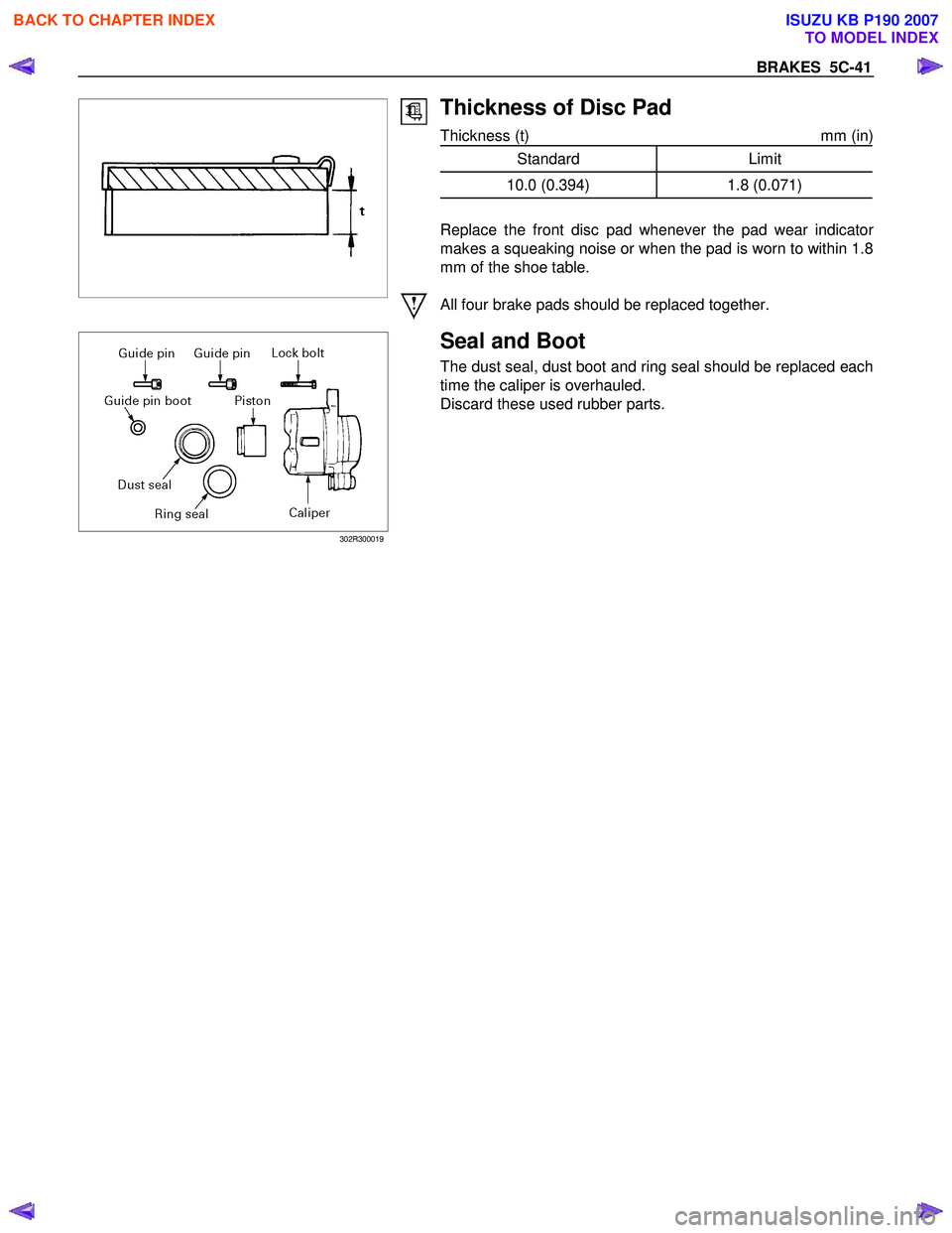
Thickness of Disc Pad
Thickness (t) mm (in)
Standard Limit
10.0 (0.394) 1.8 (0.071)
Replace the front disc pad whenever the pad wear indicato
r
makes a squeaking noise or when the pad is worn to within 1.8
mm of the shoe table.
All four brake pads should be replaced together.
302R300019
Seal and Boot
The dust seal, dust boot and ring seal should be replaced each
time the caliper is overhauled.
Discard these used rubber parts.
BACK TO CHAPTER INDEX
TO MODEL INDEX
ISUZU KB P190 2007
Page 742 of 6020
BRAKES 5C-43
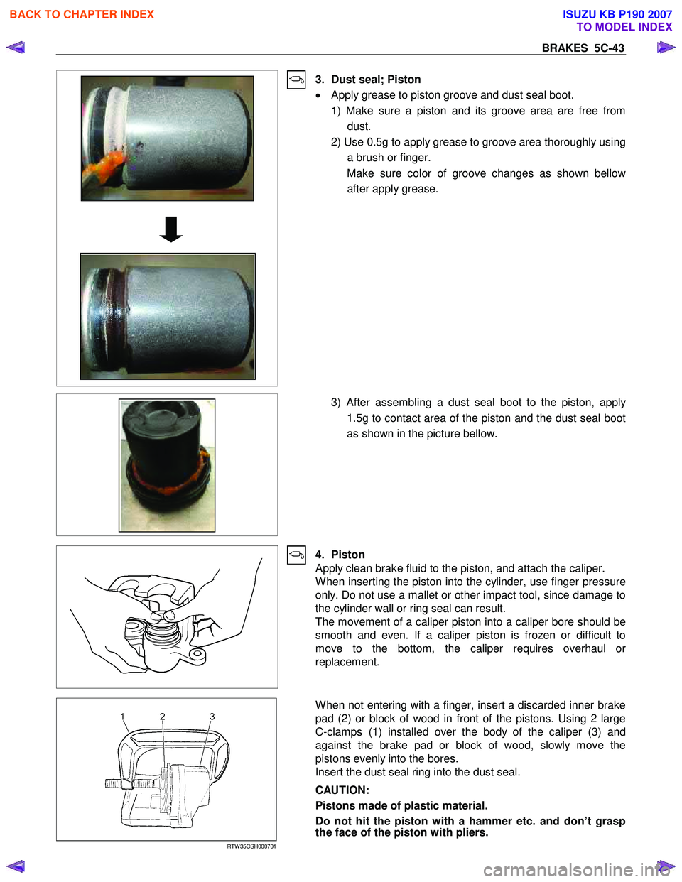
3. Dust seal; Piston
• Apply grease to piston groove and dust seal boot.
1) Make sure a piston and its groove area are free from dust.
2) Use 0.5g to apply grease to groove area thoroughly using a brush or finger.
Make sure color of groove changes as shown bello
w
after apply grease.
3) After assembling a dust seal boot to the piston, apply
1.5g to contact area of the piston and the dust seal boot
as shown in the picture bellow.
4. Piston
Apply clean brake fluid to the piston, and attach the caliper.
W hen inserting the piston into the cylinder, use finger pressure
only. Do not use a mallet or other impact tool, since damage to
the cylinder wall or ring seal can result.
The movement of a caliper piston into a caliper bore should be
smooth and even. If a caliper piston is frozen or difficult to
move to the bottom, the caliper requires overhaul o
r
replacement.
RTW 35CSH000701
W hen not entering with a finger, insert a discarded inner brake
pad (2) or block of wood in front of the pistons. Using 2 large
C-clamps (1) installed over the body of the caliper (3) and
against the brake pad or block of wood, slowly move the
pistons evenly into the bores.
Insert the dust seal ring into the dust seal.
CAUTION:
Pistons made of plastic material.
Do not hit the piston with a hammer etc. and don’t grasp
the face of the piston with pliers.
BACK TO CHAPTER INDEX
TO MODEL INDEX
ISUZU KB P190 2007
Page 744 of 6020
BRAKES 5C-45
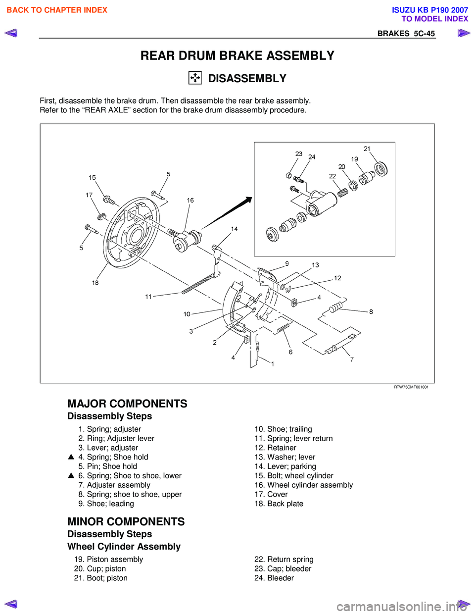
REAR DRUM BRAKE ASSEMBLY
DISASSEMBLY
First, disassemble the brake drum. Then disassemble the rear brake assembly.
Refer to the “REAR AXLE” section for the brake drum disassembly procedure.
RTW 75CMF001001
MAJOR COMPONENTS
Disassembly Steps
1. Spring; adjuster
2. Ring; Adjuster lever
3. Lever; adjuster
▲ 4. Spring; Shoe hold
5. Pin; Shoe hold
▲ 6. Spring; Shoe to shoe, lower
7. Adjuster assembly
8. Spring; shoe to shoe, upper
9. Shoe; leading
10. Shoe; trailing
11. Spring; lever return
12. Retainer
13. W asher; lever
14. Lever; parking
15. Bolt; wheel cylinder
16. W heel cylinder assembly
17. Cover
18. Back plate
MINOR COMPONENTS
Disassembly Steps
Wheel Cylinder Assembly
19. Piston assembly
20. Cup; piston
21. Boot; piston
22. Return spring
23. Cap; bleeder
24. Bleeder
BACK TO CHAPTER INDEX
TO MODEL INDEX
ISUZU KB P190 2007
Page 747 of 6020
5C-48 BRAKES
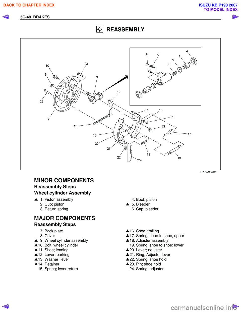
REASSEMBLY
RTW 75CMF000601
MINOR COMPONENTS
Reassembly Steps
Wheel cylinder Assembly
▲ 1. Piston assembly
2. Cup; piston
3. Return spring
4. Boot; piston
▲ 5. Bleeder
6. Cap; bleeder
MAJOR COMPONENTS
Reassembly Steps
7. Back plate
8. Cover
▲ 9. W heel cylinder assembly
▲ 10. Bolt; wheel cylinder
▲ 11. Shoe; leading
▲ 12. Lever; parking
▲ 13. W asher; lever
▲ 14. Retainer
15. Spring; lever return
▲
16. Shoe; trailing
▲ 17. Spring; shoe to shoe, upper
▲ 18. Adjuster assembly
19. Spring; shoe to shoe; lower
▲ 20. Lever; adjuster
▲ 21. Ring; Adjuster lever
▲ 22. Spring; shoe hold
▲ 23. Pin; shoe hold
24. Spring; adjuster
BACK TO CHAPTER INDEX
TO MODEL INDEX
ISUZU KB P190 2007
Page 748 of 6020
BRAKES 5C-49
Important Operations
Note:
• W ash the disassembled parts in clean brake fluid.
• Use compressed air to clean the ports.
• Protect the disassembled part surfaces from contamination
by dust and other foreign material.
• Before reassembly, check the part surfaces fo
r
contamination with dust or other foreign material.
• Be sure to replace the designated parts with new ones.
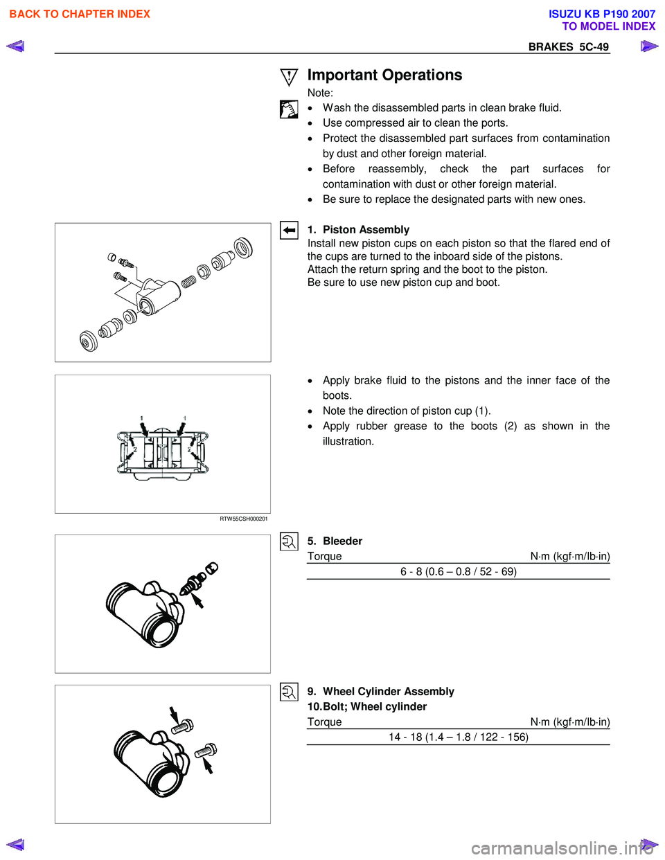
1. Piston Assembly
Install new piston cups on each piston so that the flared end of
the cups are turned to the inboard side of the pistons.
Attach the return spring and the boot to the piston.
Be sure to use new piston cup and boot.
RTW 55CSH000201
•
Apply brake fluid to the pistons and the inner face of the
boots.
• Note the direction of piston cup (1).
• Apply rubber grease to the boots (2) as shown in the
illustration.
5. Bleeder
Torque N ⋅m (kgf ⋅m/Ib ⋅in)
6 - 8 (0.6 – 0.8 / 52 - 69)
9. Wheel Cylinder Assembly
10. Bolt; Wheel cylinder
Torque N ⋅m (kgf ⋅m/Ib ⋅in)
14 - 18 (1.4 – 1.8 / 122 - 156)
BACK TO CHAPTER INDEX
TO MODEL INDEX
ISUZU KB P190 2007
Page 3273 of 6020
Engine Management – V6 – General Information Page 6C1-1–31
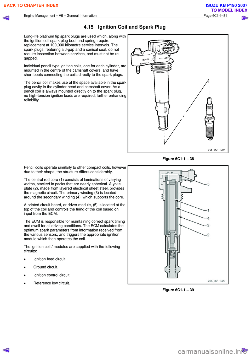
4.15 Ignition Coil and Spark Plug
Long-life platinum tip spark plugs are used which, along with
the ignition coil spark plug boot and spring, require
replacement at 100,000 kilometre service intervals. The
spark plugs, featuring a J-gap and a conical seat, do not
require inspection between services, and must not be re-
gapped.
Individual pencil-type ignition coils, one for each cylinder, are
mounted in the centre of the camshaft covers, and have
short boots connecting the coils directly to the spark plugs.
The pencil coil makes use of the space available in the spark
plug cavity in the cylinder head and camshaft cover. As a
pencil coil is always mounted directly on to the spark plug,
no high-tension ignition leads are required, further enhancing
reliability.
Figure 6C1-1 – 38
Pencil coils operate similarly to other compact coils, however
due to their shape, the structure differs considerably.
The central rod core (1) consists of laminations of varying
widths, stacked in packs that are nearly spherical. A yoke
plate (2), made from layered electrical sheet steel, provides
the magnetic circuit. The primary winding (3) is located
around the secondary winding (4), which supports the core.
A printed circuit board, or driver module, (5) is located at the
top of the coil and controls the firing of the coil based on
input from the ECM.
The ECM is responsible for maintaining correct spark timing
and dwell for all driving conditions. The ECM calculates the
optimum spark parameters from information received from
the various sensors, and triggers the appropriate ignition
module which then operates the coil.
The ignition coil / modules are supplied with the following
circuits:
• Ignition feed circuit.
• Ground circuit.
• Ignition control circuit.
• Reference low circuit.
Figure 6C1-1 – 39
BACK TO CHAPTER INDEX
TO MODEL INDEX
ISUZU KB P190 2007
Page 3384 of 6020
Engine Management – V6 – Diagnostics Page 6C1-2–106
− Damaged accessory drive belt
• For an intermittent condition, refer to 5.2 Intermittent Fault Conditions in this Section.
• Since a fault condition in a wiring connector may trigger DTCs, always test the connectors related to this
diagnostic procedure for shorted terminals or poor wiring connection before replacing any component. Refer to 8A
Electrical - Body and Chassis for information on electrical fault diagnosis.
• To assist diagnosis, refer to 3 W iring Diagrams and Connector Charts in this Section, for the system wiring
diagram and connector charts.
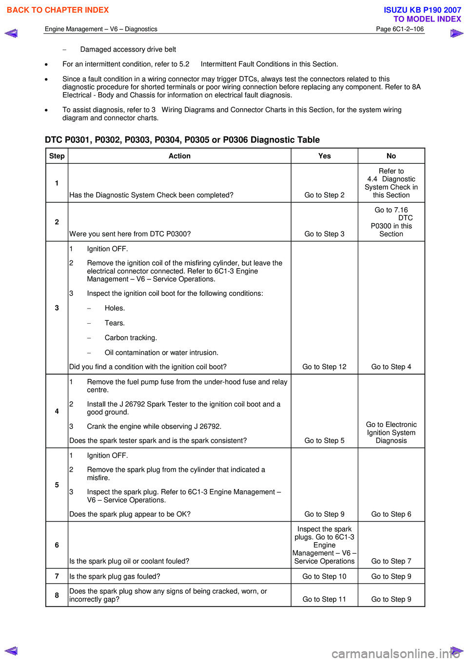
DTC P0301, P0302, P0303, P0304, P0305 or P0306 Diagnostic Table
Step Action Yes No
1
Has the Diagnostic System Check been completed? Go to Step 2 Refer to
4.4 Diagnostic
System Check in this Section
2
W ere you sent here from DTC P0300? Go to Step 3 Go to 7.16
DTC P0300 in this Section
3 1 Ignition OFF.
2 Remove the ignition coil of the misfiring cylinder, but leave the electrical connector connected. Refer to 6C1-3 Engine
Management – V6 – Service Operations.
3 Inspect the ignition coil boot for the following conditions:
− Holes.
− Tears.
− Carbon tracking.
− Oil contamination or water intrusion.
Did you find a condition with the ignition coil boot? Go to Step 12 Go to Step 4
4 1 Remove the fuel pump fuse from the under-hood fuse and relay
centre.
2 Install the J 26792 Spark Tester to the ignition coil boot and a good ground.
3 Crank the engine while observing J 26792.
Does the spark tester spark and is the spark consistent? Go to Step 5 Go to Electronic
Ignition System Diagnosis
5 1 Ignition OFF.
2 Remove the spark plug from the cylinder that indicated a misfire.
3 Inspect the spark plug. Refer to 6C1-3 Engine Management – V6 – Service Operations.
Does the spark plug appear to be OK? Go to Step 9 Go to Step 6
6
Is the spark plug oil or coolant fouled? Inspect the spark
plugs. Go to 6C1-3 Engine
Management – V6 – Service Operations Go to Step 7
7 Is the spark plug gas fouled? Go to Step 10 Go to Step 9
8 Does the spark plug show any signs of being cracked, worn, or
incorrectly gap? Go to Step 11 Go to Step 9
BACK TO CHAPTER INDEX
TO MODEL INDEX
ISUZU KB P190 2007