Diagram ISUZU KB P190 2007 Workshop Workshop Manual
[x] Cancel search | Manufacturer: ISUZU, Model Year: 2007, Model line: KB P190, Model: ISUZU KB P190 2007Pages: 6020, PDF Size: 70.23 MB
Page 2418 of 6020
6E–248 ENGINE DRIVEABILITY AND EMISSIONS
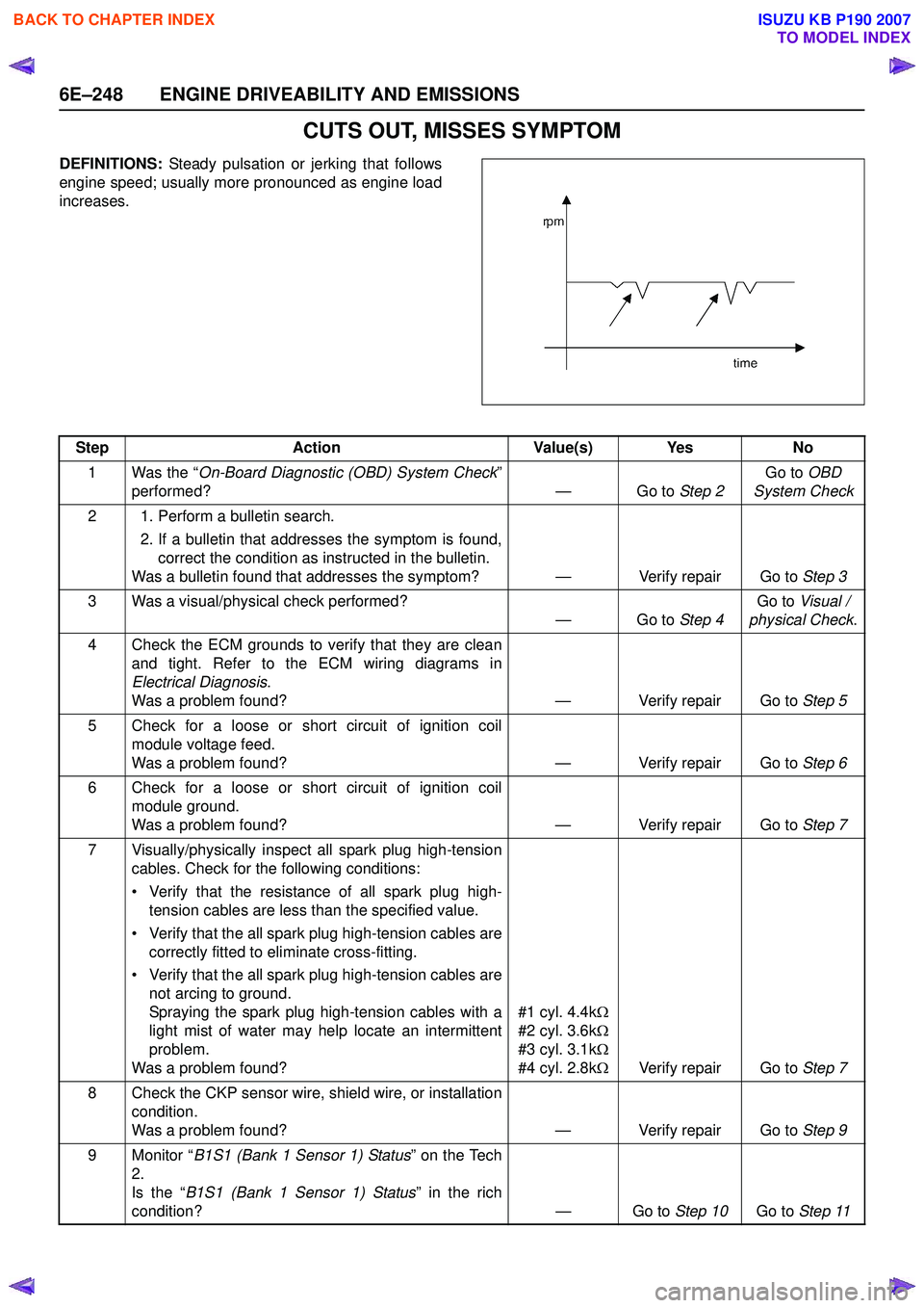
CUTS OUT, MISSES SYMPTOM
DEFINITIONS: Steady pulsation or jerking that follows
engine speed; usually more pronounced as engine load
increases.
Step Action Value(s) Yes No
1 Was the “ On-Board Diagnostic (OBD) System Check ”
performed? — Go to Step 2Go to
OBD
System Check
2 1. Perform a bulletin search. 2. If a bulletin that addresses the symptom is found,correct the condition as instructed in the bulletin.
Was a bulletin found that addresses the symptom? — Verify repair Go to Step 3
3 Was a visual/physical check performed? —Go to Step 4Go to
Visual /
physical Check .
4 Check the ECM grounds to verify that they are clean and tight. Refer to the ECM wiring diagrams in
Electrical Diagnosis .
Was a problem found? — Verify repair Go to Step 5
5 Check for a loose or short circuit of ignition coil module voltage feed.
Was a problem found? — Verify repair Go to Step 6
6 Check for a loose or short circuit of ignition coil module ground.
Was a problem found? — Verify repair Go to Step 7
7 Visually/physically inspect all spark plug high-tension cables. Check for the following conditions:
• Verify that the resistance of all spark plug high- tension cables are less than the specified value.
• Verify that the all spark plug high-tension cables are correctly fitted to eliminate cross-fitting.
• Verify that the all spark plug high-tension cables are not arcing to ground.
Spraying the spark plug high-tension cables with a
light mist of water may help locate an intermittent
problem.
Was a problem found? #1 cyl. 4.4k
Ω
#2 cyl. 3.6k Ω
#3 cyl. 3.1k Ω
#4 cyl. 2.8k ΩVerify repair Go to Step 7
8 Check the CKP sensor wire, shield wire, or installation condition.
Was a problem found? — Verify repair Go to Step 9
9 Monitor “ B1S1 (Bank 1 Sensor 1) Status ” on the Tech
2.
Is the “ B1S1 (Bank 1 Sensor 1) Status ” in the rich
condition? — Go to Step 10Go to Step 11
BACK TO CHAPTER INDEX
TO MODEL INDEX
ISUZU KB P190 2007
Page 2421 of 6020
ENGINE DRIVEABILITY AND EMISSIONS 6E–251
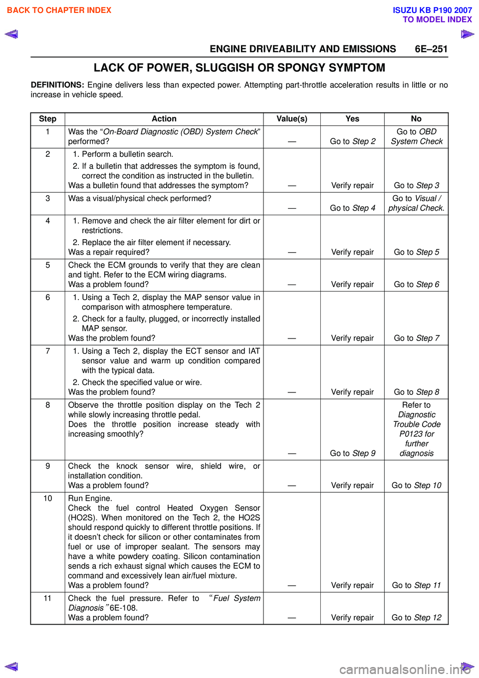
LACK OF POWER, SLUGGISH OR SPONGY SYMPTOM
DEFINITIONS: Engine delivers less than expected power. Attempting part-throttle acceleration results in little or no
increase in vehicle speed.
Step Action Value(s) Yes No
1 Was the “ On-Board Diagnostic (OBD) System Check ”
performed? — Go to Step 2Go to
OBD
System Check
2 1. Perform a bulletin search. 2. If a bulletin that addresses the symptom is found,correct the condition as instructed in the bulletin.
Was a bulletin found that addresses the symptom? — Verify repair Go to Step 3
3 Was a visual/physical check performed? —Go to Step 4Go to
Visual /
physical Check .
4 1. Remove and check the air filter element for dirt or restrictions.
2. Replace the air filter element if necessary.
Was a repair required? — Verify repair Go to Step 5
5 Check the ECM grounds to verify that they are clean and tight. Refer to the ECM wiring diagrams.
Was a problem found? — Verify repair Go to Step 6
6 1. Using a Tech 2, display the MAP sensor value in comparison with atmosphere temperature.
2. Check for a faulty, plugged, or incorrectly installed MAP sensor.
Was the problem found? — Verify repair Go to Step 7
7 1. Using a Tech 2, display the ECT sensor and IAT sensor value and warm up condition compared
with the typical data.
2. Check the specified value or wire.
Was the problem found? — Verify repair Go to Step 8
8 Observe the throttle position display on the Tech 2 while slowly increasing throttle pedal.
Does the throttle position increase steady with
increasing smoothly?
—Go to Step 9Refer to
Diagnostic
Trouble Code P0123 for further
diagnosis
9 Check the knock sensor wire, shield wire, or installation condition.
Was a problem found? — Verify repair Go to Step 10
10 Run Engine. Check the fuel control Heated Oxygen Sensor
(HO2S). When monitored on the Tech 2, the HO2S
should respond quickly to different throttle positions. If
it doesn’t check for silicon or other contaminates from
fuel or use of improper sealant. The sensors may
have a white powdery coating. Silicon contamination
sends a rich exhaust signal which causes the ECM to
command and excessively lean air/fuel mixture.
Was a problem found? — Verify repair Go to Step 11
11 Check the fuel pressure. Refer to “Fuel System
Diagnosis
” 6E-108.
Was a problem found? — Verify repair Go to Step 12
BACK TO CHAPTER INDEX
TO MODEL INDEX
ISUZU KB P190 2007
Page 3136 of 6020

Engine Cooling – V6 Engine Page 6B1–1
Section 6B1
Engine Cooling – V6
ATTENTION
Before performing any Service Operation or other procedure described in this Section, refer to 1.1 WARNING,
CAUTION and NOTES for correct workshop practices with regard to safety and/or property damage.
1 General Information ............................................................................................................ ...................3
1.1 WARNING, CAUTION and NOTES ..................................................................................................... ................... 4
1.2 Definition of WARNING, CAUTION and NOTE Statements ......................................................................... .. 4
WARNING defined ............................................................................................................................................. 4
CAUTION defined .............................................................................................................................................. 4
NOTE defined..................................................................................................................................................... 4
2 General Description ............................................................................................................ ...................5
2.1 Radiator Assembly .............................................................................................................. .................................. 5
2.2 Cooling Fan – Standard Specification.................................................................................................................. 7
Overview ................................................................................................................................................................. 7
Cooling Fan and Shroud Assembly ................................................................................................ .................... 8
Fan Motor ........................................................................................................................................................... 8
Fan Operation .................................................................................................................. .................................. 8
V6 Cooling Fan Wiring Diagram .................................................................................................. ....................... 9
Fan Assembly connector .................................................................................................................................. 10
2.3 Coolant Pump....................................................................................................................................................... 10
2.4 Coolant Outlet Housing ......................................................................................................... .............................. 11
2.5 Thermostat ........................................................................................................................................................... 11
2.6 Coolant Filler Cap ............................................................................................................. ................................... 13
2.7 Coolant Recovery Reservoir ..................................................................................................... .......................... 14
2.8 Engine Coolant Temperature Sensor .............................................................................................. ................... 15
3 Service Operations ...............................................................................................................................16
3.1 Service Notes ....................................................................................................................................................... 16
Safety .................................................................................................................................................................... 16
Periodic Servicing............................................................................................................. ................................... 16
Environmental Issues ........................................................................................................... ............................... 16
3.2 Coolant Maintenance ........................................................................................................................................... 17
Topping Up the Cooling System.................................................................................................. ....................... 18
Testing Coolant Concentration........................................................................................................................... 18
Method 1 – Refractometer................................................................................................................................ 18
Method 2 – Hydrometer.................................................................................................................................... 21
3.3 Draining and Filling Cooling System ............................................................................................ ..................... 22
Draining ................................................................................................................................................................ 22
Filling .................................................................................................................................................................... 22
3.4 Cleaning Cooling System ........................................................................................................ ............................ 25
Cooling System Reverse Flush ................................................................................................... ....................... 25
Radiator............................................................................................................................................................ 25
Engine .............................................................................................................................................................. 26
Heater Hoses and Core.......................................................................................................... .......................... 27
3.5 Drive Belt Tension ............................................................................................................................................... 28
Inspect .................................................................................................................................................................. 29
3.6 Coolant Hoses ...................................................................................................................................................... 30
3.7 Pressure Testing ............................................................................................................... ................................... 31
Coolant Filler Cap Pressure Testing ............................................................................................ ...................... 31
BACK TO CHAPTER INDEX
TO MODEL INDEX
ISUZU KB P190 2007
Page 3144 of 6020
Engine Cooling – V6 Engine Page 6B1–9
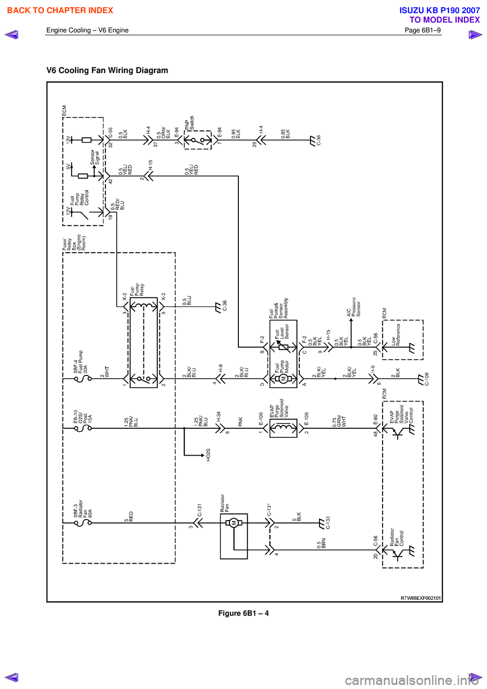
V6 Cooling Fan Wiring Diagram
Figure 6B1 – 4
BACK TO CHAPTER INDEX
TO MODEL INDEX
ISUZU KB P190 2007
Page 3279 of 6020
Engine Management – V6 – Diagnostics Page 6C1-2–1
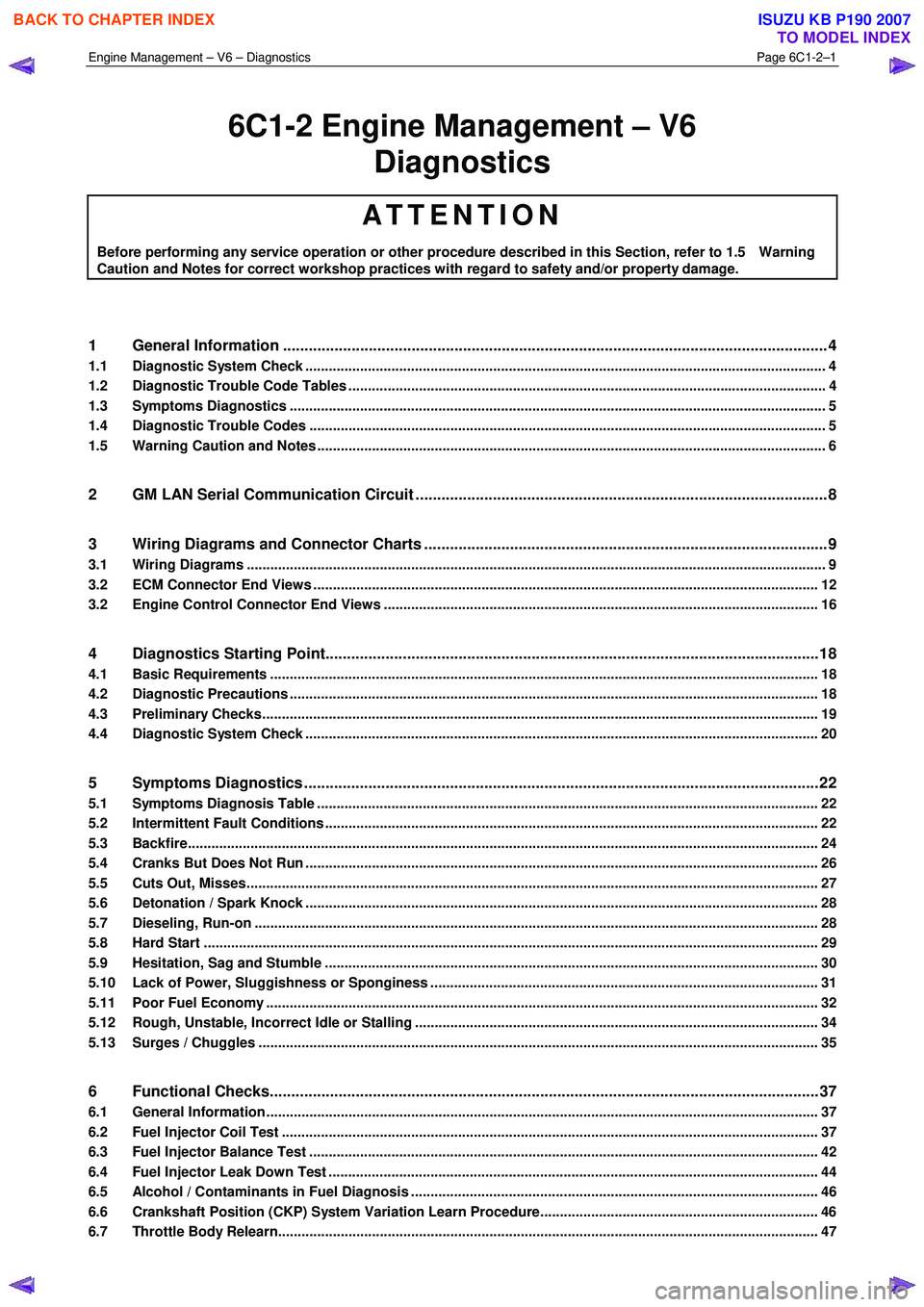
6C1-2 Engine Management – V6
Diagnostics
ATTENTION
Before performing any service operation or other procedure described in this Section, refer to 1.5 Warning
Caution and Notes for correct workshop practices with regard to safety and/or property damage.
1 General Information ............................................................................................................ ...................4
1.1 Diagnostic System Check ..................................................................................................................................... 4
1.2 Diagnostic Trouble Code Tables ................................................................................................. ......................... 4
1.3 Symptoms Diagnostics ......................................................................................................................................... 5
1.4 Diagnostic Trouble Codes .................................................................................................................................... 5
1.5 Warning Caution and Notes .................................................................................................................................. 6
2 GM LAN Serial Communication Circuit ............................................................................................ ....8
3 Wiring Diagrams and Connector Charts ........................................................................................... ...9
3.1 Wiring Diagrams .................................................................................................................................................... 9
3.2 ECM Connector End Views ................................................................................................................................. 12
3.2 Engine Control Connector End Views ............................................................................................. .................. 16
4 Diagnostics Starting Point...................................................................................................................18
4.1 Basic Requirements ............................................................................................................................................ 18
4.2 Diagnostic Precautions ......................................................................................................... .............................. 18
4.3 Preliminary Checks.............................................................................................................................................. 19
4.4 Diagnostic System Check ........................................................................................................ ........................... 20
5 Symptoms Diagnostics ........................................................................................................................22
5.1 Symptoms Diagnosis Table ....................................................................................................... ......................... 22
5.2 Intermittent Fault Conditions .............................................................................................................................. 22
5.3 Backfire................................................................................................................................................................. 24
5.4 Cranks But Does Not Run ........................................................................................................ ........................... 26
5.5 Cuts Out, Misses.................................................................................................................................................. 27
5.6 Detonation / Spark Knock ....................................................................................................... ............................ 28
5.7 Dieseling, Run-on ................................................................................................................................................ 28
5.8 Hard Start ............................................................................................................................................................. 29
5.9 Hesitation, Sag and Stumble .................................................................................................... .......................... 30
5.10 Lack of Power, Sluggishness or Sponginess ...................................................................................... ............. 31
5.11 Poor Fuel Economy ............................................................................................................................................. 32
5.12 Rough, Unstable, Incorrect Idle or Stalling .................................................................................... ................... 34
5.13 Surges / Chuggles ............................................................................................................................................... 35
6 Functional Checks................................................................................................................................37
6.1 General Information ............................................................................................................ ................................. 37
6.2 Fuel Injector Coil Test ......................................................................................................................................... 37
6.3 Fuel Injector Balance Test ..................................................................................................... ............................. 42
6.4 Fuel Injector Leak Down Test ................................................................................................... .......................... 44
6.5 Alcohol / Contaminants in Fuel Diagnosis ....................................................................................... ................. 46
6.6 Crankshaft Position (CKP) System Variation Learn Procedure..................................................................... .. 46
6.7 Throttle Body Relearn.......................................................................................................................................... 47
BACK TO CHAPTER INDEX
TO MODEL INDEX
ISUZU KB P190 2007
Page 3282 of 6020
Engine Management – V6 – Diagnostics Page 6C1-2–4
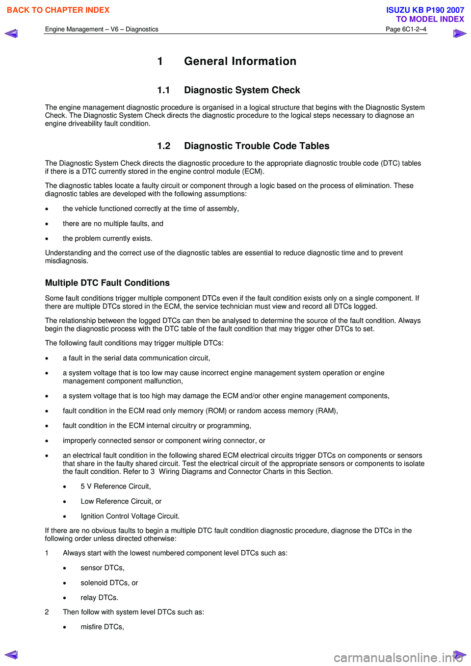
1 General Information
1.1 Diagnostic System Check
The engine management diagnostic procedure is organised in a logical structure that begins with the Diagnostic System
Check. The Diagnostic System Check directs the diagnostic procedure to the logical steps necessary to diagnose an
engine driveability fault condition.
1.2 Diagnostic Trouble Code Tables
The Diagnostic System Check directs the diagnostic procedure to the appropriate diagnostic trouble code (DTC) tables
if there is a DTC currently stored in the engine control module (ECM).
The diagnostic tables locate a faulty circuit or component through a logic based on the process of elimination. These
diagnostic tables are developed with the following assumptions:
• the vehicle functioned correctly at the time of assembly,
• there are no multiple faults, and
• the problem currently exists.
Understanding and the correct use of the diagnostic tables are essential to reduce diagnostic time and to prevent
misdiagnosis.
Multiple DTC Fault Conditions
Some fault conditions trigger multiple component DTCs even if the fault condition exists only on a single component. If
there are multiple DTCs stored in the ECM, the service technician must view and record all DTCs logged.
The relationship between the logged DTCs can then be analysed to determine the source of the fault condition. Always
begin the diagnostic process with the DTC table of the fault condition that may trigger other DTCs to set.
The following fault conditions may trigger multiple DTCs:
• a fault in the serial data communication circuit,
• a system voltage that is too low may cause incorrect engine management system operation or engine
management component malfunction,
• a system voltage that is too high may damage the ECM and/or other engine management components,
• fault condition in the ECM read only memory (ROM) or random access memory (RAM),
• fault condition in the ECM internal circuitry or programming,
• improperly connected sensor or component wiring connector, or
• an electrical fault condition in the following shared ECM electrical circuits trigger DTCs on components or sensors
that share in the faulty shared circuit. Test the electrical circuit of the appropriate sensors or components to isolate
the fault condition. Refer to 3 W iring Diagrams and Connector Charts in this Section.
• 5 V Reference Circuit,
• Low Reference Circuit, or
• Ignition Control Voltage Circuit.
If there are no obvious faults to begin a multiple DTC fault condition diagnostic procedure, diagnose the DTCs in the
following order unless directed otherwise:
1 Always start with the lowest numbered component level DTCs such as:
• sensor DTCs,
• solenoid DTCs, or
• relay DTCs.
2 Then follow with system level DTCs such as:
• misfire DTCs,
BACK TO CHAPTER INDEX
TO MODEL INDEX
ISUZU KB P190 2007
Page 3287 of 6020
Engine Management – V6 – Diagnostics Page 6C1-2–9
3 Wiring Diagrams and Connector
Charts
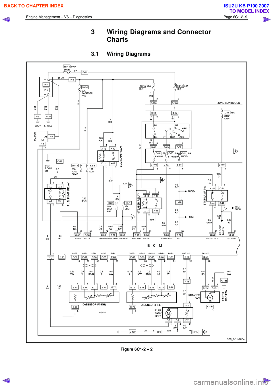
3.1 Wiring Diagrams
Figure 6C1-2 – 2
BACK TO CHAPTER INDEX
TO MODEL INDEX
ISUZU KB P190 2007
Page 3326 of 6020
Engine Management – V6 – Diagnostics Page 6C1-2–48
Additional Information
• Use the J 35616-B Connector Test Adapter Kit for any test that requires probing the ECM harness connector or a
component harness connector.
• Inspect the ignition coils for aftermarket devices. An aftermarket device connected to the ignition coil circuits, may
cause a condition with the ignition coils.
• For an intermittent fault condition, refer to 5.2 Intermittent Fault Conditions in this Section.
• To assist diagnosis, refer to 3 W iring Diagrams and Connector Charts in this Section, for the system wiring
diagram and connector charts.
Test Description
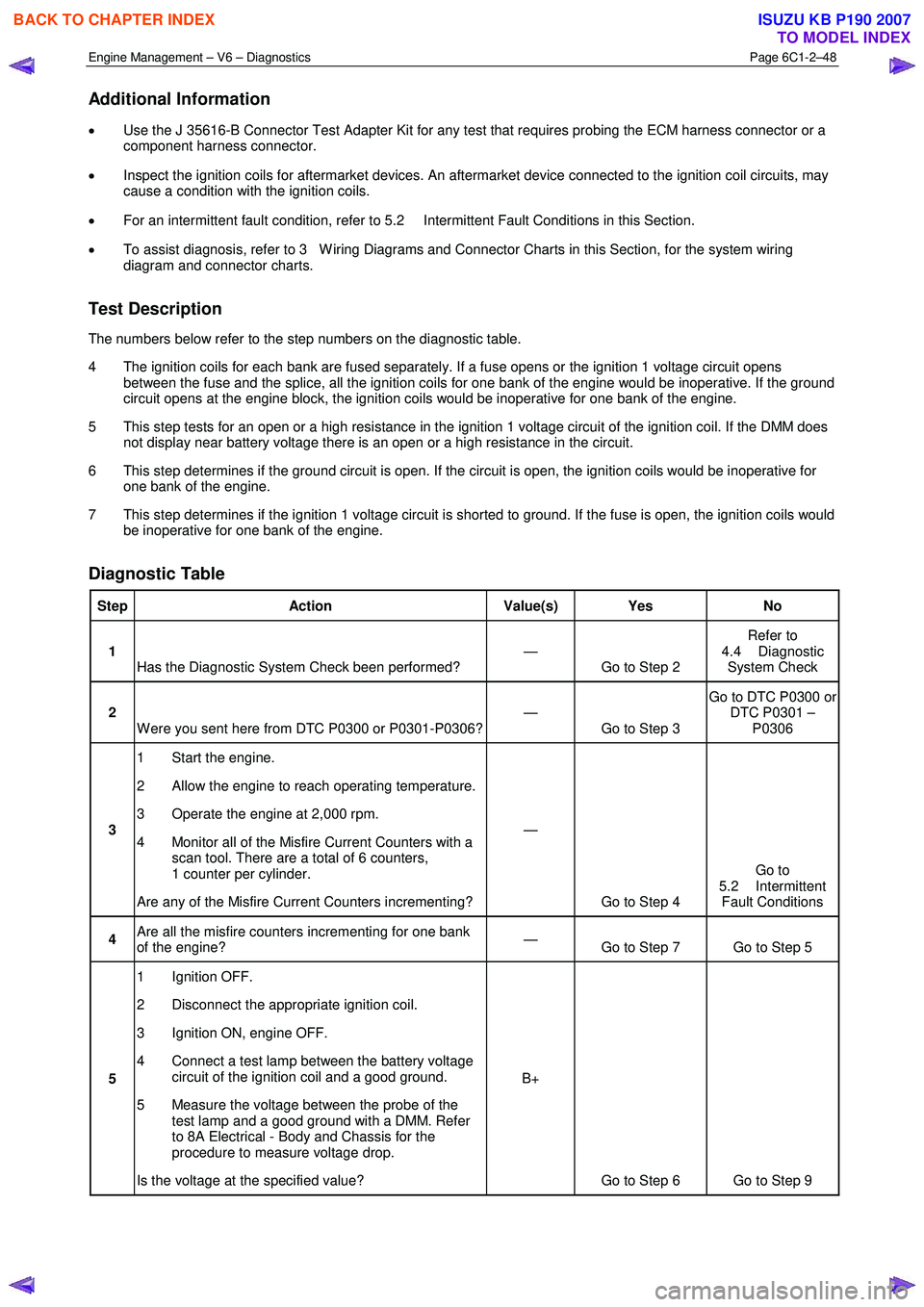
The numbers below refer to the step numbers on the diagnostic table.
4 The ignition coils for each bank are fused separately. If a fuse opens or the ignition 1 voltage circuit opens between the fuse and the splice, all the ignition coils for one bank of the engine would be inoperative. If the ground
circuit opens at the engine block, the ignition coils would be inoperative for one bank of the engine.
5 This step tests for an open or a high resistance in the ignition 1 voltage circuit of the ignition coil. If the DMM does not display near battery voltage there is an open or a high resistance in the circuit.
6 This step determines if the ground circuit is open. If the circuit is open, the ignition coils would be inoperative for one bank of the engine.
7 This step determines if the ignition 1 voltage circuit is shorted to ground. If the fuse is open, the ignition coils would be inoperative for one bank of the engine.
Diagnostic Table
Step Action Value(s) Yes No
1
Has the Diagnostic System Check been performed? —
Go to Step 2 Refer to
4.4 Diagnostic System Check
2 W ere you sent here from DTC P0300 or P0301-P0306? —
Go to Step 3 Go to DTC P0300 or
DTC P0301 – P0306
3 1 Start the engine.
2 Allow the engine to reach operating temperature.
3 Operate the engine at 2,000 rpm.
4 Monitor all of the Misfire Current Counters with a scan tool. There are a total of 6 counters,
1 counter per cylinder.
Are any of the Misfire Current Counters incrementing? —
Go to Step 4 Go to
5.2 Intermittent Fault Conditions
4 Are all the misfire counters incrementing for one bank
of the engine? —
Go to Step 7 Go to Step 5
5 1 Ignition OFF.
2 Disconnect the appropriate ignition coil.
3 Ignition ON, engine OFF.
4 Connect a test lamp between the battery voltage circuit of the ignition coil and a good ground.
5 Measure the voltage between the probe of the test lamp and a good ground with a DMM. Refer
to 8A Electrical - Body and Chassis for the
procedure to measure voltage drop.
Is the voltage at the specified value? B+
Go to Step 6 Go to Step 9
BACK TO CHAPTER INDEX
TO MODEL INDEX
ISUZU KB P190 2007
Page 3339 of 6020

Engine Management – V6 – Diagnostics Page 6C1-2–61
• DTCs P0341, P0342, P0343, ran and passed:
• The engine is running.
• The ECM has learned the camshafts position.
DTC P0016
Run continuously once the following conditions are met.
• DTCs P0335, P0336, P0338, P0341, P0342 and P0343 ran and passed:
• The calculated engine oil temperature is less than 95 °C.
• The engine coolant temperature is 20 – 90 °C.
• The engine is running for greater than 5 seconds.
Conditions for Setting the DTC
DTC P0008
The ECM detects that both camshafts on bank 1 of the engine are misaligned with the crankshaft.
DTC P0009
The ECM detects that both camshafts on bank 2 of the engine are misaligned with the crankshaft.
DTC P0016
The ECM detects the following deviation in the correlation between the camshaft position and the crankshaft position for
greater than 10 minutes:
• a camshaft position is too advanced in relationship to the crankshaft, or
• a camshaft position is too retarded in relationship to the crankshaft.
Conditions for Clearing DTC
The CKP / CMP sensor correlation DTCs are Type B DTCs. Refer to 1.4 Diagnostic Trouble Codes in this Section, for
action taken when Type B DTCs set and conditions for clearing Type B DTCs.
Additional Information
• Refer to 6C1-1 Engine Management – V6 – General Information for details of the CMP system operation.
• Inspect the engine for recent engine mechanical repairs. Incorrect camshaft, camshaft actuator or timing chain
installation will trigger these DTCs.
• The engine oil condition has a major impact on the operation of the camshaft actuator.
• A low oil level may set these DTCs.
• For an intermittent fault condition, refer to 5.2 Intermittent Fault Conditions in this Section.
• Since fault condition in a wiring connector may trigger DTCs, always test the connectors related to this diagnostic
procedure for shorted terminals or poor wiring connection before replacing any component. Refer to 8A Electrical -
Body and Chassis for information on electrical fault diagnosis.
• To assist diagnosis, refer to 3 W iring Diagrams and Connector Charts in this Section, for the system wiring
diagram and connector charts.
Test Description
The following numbers refer to the step numbers in the diagnostic table:
3 A fault condition in any of the listed sensors will trigger these DTCs.
5 Incorrect camshaft, camshaft actuator or timing chain installation will trigger these DTCs.
BACK TO CHAPTER INDEX
TO MODEL INDEX
ISUZU KB P190 2007
Page 3342 of 6020
Engine Management – V6 – Diagnostics Page 6C1-2–64
• Inspect the HO2S wiring harness for contact with the exhaust system.
• The front and the rear HO2Ss have a separate fuse connection. If both front or both the rear DTCs are set, the
appropriate HO2S ignition voltage circuit may be open.
• Since fault condition in a wiring connector may trigger DTCs, always test the connectors related to this diagnostic
procedure for shorted terminals or poor wiring connection before replacing any component. Refer to 8A Electrical -
Body and Chassis for information on electrical fault diagnosis.
• To assist diagnosis, refer to 3 W iring Diagrams and Connector Charts in this Section, for the system wiring
diagram and connector charts.
Test Description
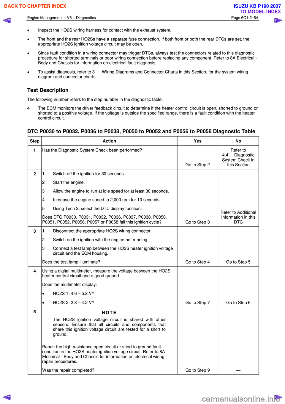
The following number refers to the step number in the diagnostic table:
4 The ECM monitors the driver feedback circuit to determine if the heater control circuit is open, shorted to ground or shorted to a positive voltage. If the voltage is outside the specified range, there is a fault condition with the heater
control circuit.
DTC P0030 to P0032, P0036 to P0038, P0050 to P0052 and P0056 to P0058 Diagnostic Table
Step Action Yes No
1 Has the Diagnostic System Check been performed?
Go to Step 2 Refer to
4.4 Diagnostic
System Check in this Section
2 1 Switch off the ignition for 30 seconds.
2 Start the engine.
3 Allow the engine to run at idle speed for at least 30 seconds.
4 Increase the engine speed to 2,000 rpm for 10 seconds.
5 Using Tech 2, select the DTC display function.
Does DTC P0030, P0031, P0032, P0036, P0037, P0038, P0050,
P0051, P0052, P0056, P0057 or P0058 fail this ignition cycle? Go to Step 3 Refer to Additional
Information in this DTC
3 1 Disconnect the appropriate HO2S wiring connector.
2 Switch on the ignition with the engine not running.
3 Connect a test lamp between the HO2S heater ignition voltage circuit and the ECM housing.
Does the test lamp illuminate? Go to Step 4 Go to Step 5
4 Using a digital multimeter, measure the voltage between the HO2S
heater control circuit and a good ground.
Does the multimeter display:
• HO2S 1: 4.6 – 5.2 V?
• HO2S 2: 2.8 – 4.2 V? Go to Step 7 Go to Step 6
5
NOTE
The HO2S ignition voltage circuit is shared with other
sensors. Ensure that all circuits and components that
share this ignition voltage circuit are tested for a short to
ground.
Repair the high resistance open circuit or short to ground fault
condition in the HO2S heater ignition voltage circuit. Refer to 8A
Electrical - Body and Chassis for information on electrical wiring
repair procedures.
W as the repair completed? Go to Step 9 —
BACK TO CHAPTER INDEX
TO MODEL INDEX
ISUZU KB P190 2007