brake sensor ISUZU KB P190 2007 Workshop Manual PDF
[x] Cancel search | Manufacturer: ISUZU, Model Year: 2007, Model line: KB P190, Model: ISUZU KB P190 2007Pages: 6020, PDF Size: 70.23 MB
Page 696 of 6020
ANTI-LOCK BRAKE SYSTEM 5B-17
RUW 55BMF000101
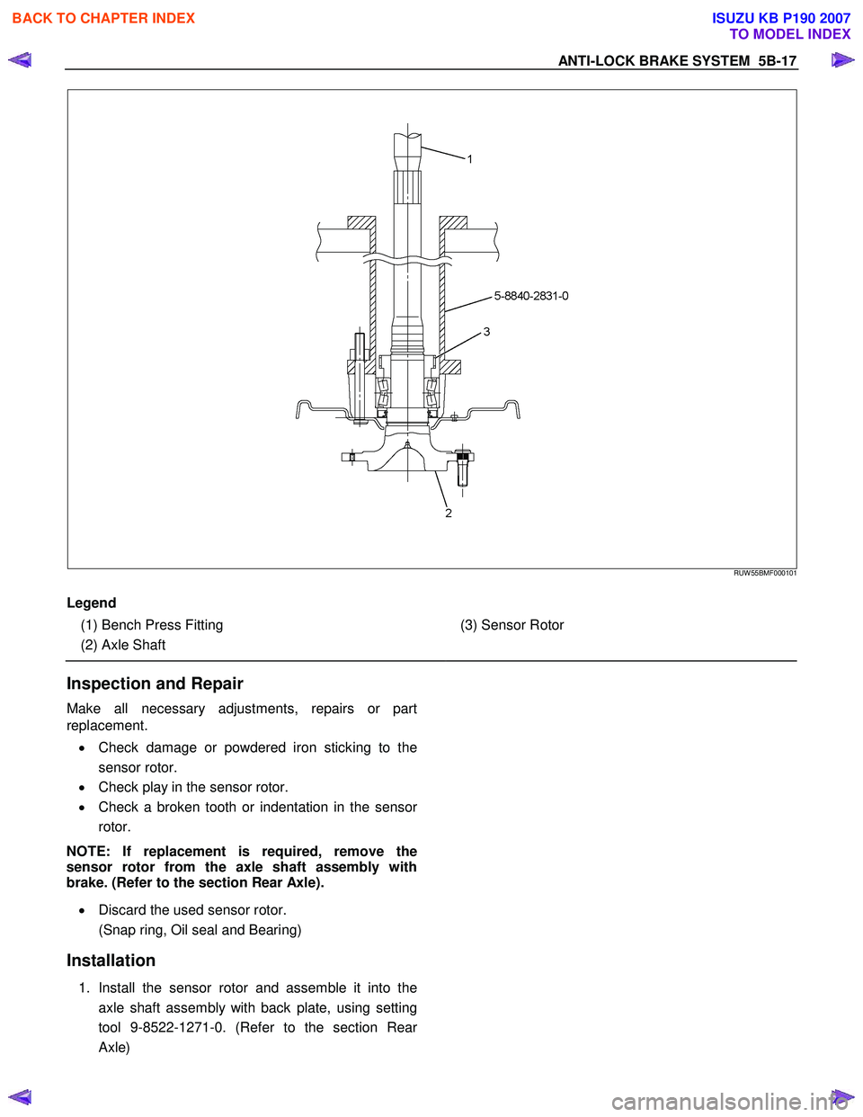
Legend
(1) Bench Press Fitting
(2) Axle Shaft
(3) Sensor Rotor
Inspection and Repair
Make all necessary adjustments, repairs or part
replacement.
• Check damage or powdered iron sticking to the
sensor rotor.
• Check play in the sensor rotor.
• Check a broken tooth or indentation in the senso
r
rotor.
NOTE: If replacement is required, remove the
sensor rotor from the axle shaft assembly with
brake. (Refer to the section Rear Axle).
• Discard the used sensor rotor.
(Snap ring, Oil seal and Bearing)
Installation
1. Install the sensor rotor and assemble it into the
axle shaft assembly with back plate, using setting
tool 9-8522-1271-0. (Refer to the section Rea
r
Axle)
BACK TO CHAPTER INDEX
TO MODEL INDEX
ISUZU KB P190 2007
Page 697 of 6020
5B-18 ANTI-LOCK BRAKE SYSTEM
420R300005
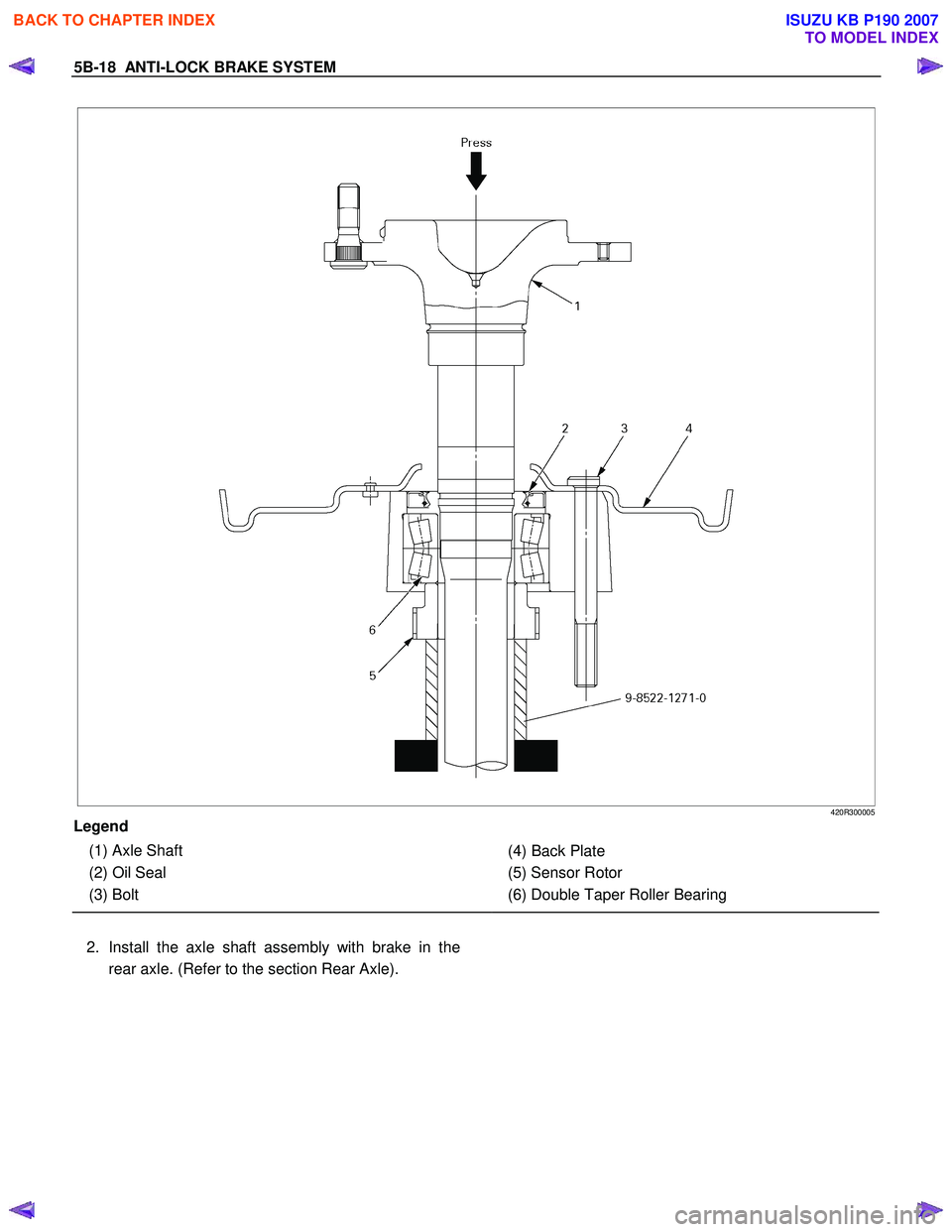
Legend
(1) Axle Shaft
(2) Oil Seal
(3) Bolt
(4) Back Plate
(5) Sensor Rotor
(6) Double Taper Roller Bearing
2. Install the axle shaft assembly with brake in the rear axle. (Refer to the section Rear Axle).
BACK TO CHAPTER INDEX
TO MODEL INDEX
ISUZU KB P190 2007
Page 698 of 6020

ANTI-LOCK BRAKE SYSTEM 5B-19
G-Sensor
G-Sensor and Associated Parts
This illustration is based on the RHD model
RTW 75BLF000101
Legend
(1) G-Sensor
(2) Nut
Removal
1. Remove the front floor console. (Refer to the section Floor Console)
2. Disconnect the connector.
3. Remove the nuts.
4. Take out the G-sensor.
Installation
1. Set the G-sensor.
2. Install the nut and tighten it to specified torque.
Torque: 8 N·m (0.8 kgf·m / 69 lb·in)
3. Connect the connector.
4. Install the front floor console. (Refer to the section Floor Console)
BACK TO CHAPTER INDEX
TO MODEL INDEX
ISUZU KB P190 2007
Page 1056 of 6020
6E-22 Engine Control System (4JH1)
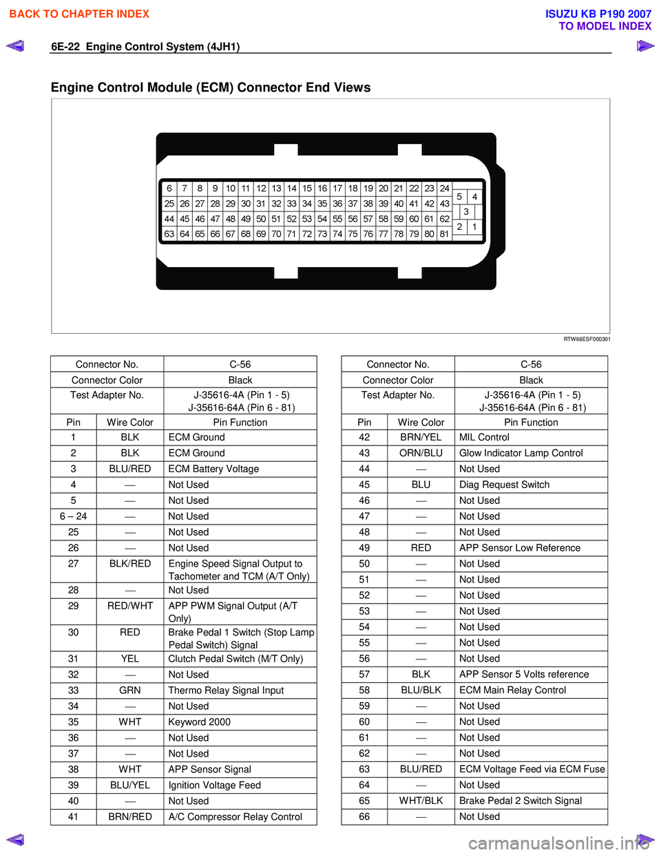
Engine Control Module (ECM) Connector End Views
RTW 66ESF000301
Connector No. C-56
Connector Color Black
Test Adapter No. J-35616-4A (Pin 1 - 5)
J-35616-64A (Pin 6 - 81)
Pin W ire Color Pin Function
1 BLK ECM Ground
2 BLK ECM Ground
3 BLU/RED ECM Battery Voltage
4 Not Used
5 Not Used
6 – 24 Not Used
25 Not Used
26 Not Used
27 BLK/RED Engine Speed Signal Output to
Tachometer and TCM (A/T Only)
28 Not Used
29 RED/W HT APP PW M Signal Output (A/T
Only)
30 RED Brake Pedal 1 Switch (Stop Lamp Pedal Switch) Signal
31 YEL Clutch Pedal Switch (M/T Only)
32 Not Used
33 GRN Thermo Relay Signal Input
34 Not Used
35 W HT Keyword 2000
36 Not Used
37 Not Used
38 W HT APP Sensor Signal
39 BLU/YEL Ignition Voltage Feed
40 Not Used
41 BRN/RED A/C Compressor Relay Control
Connector No. C-56
Connector Color Black
Test Adapter No. J-35616-4A (Pin 1 - 5)
J-35616-64A (Pin 6 - 81)
Pin W ire Color Pin Function
42 BRN/YEL MIL Control
43 ORN/BLU Glow Indicator Lamp Control
44 Not Used
45 BLU Diag Request Switch
46 Not Used
47 Not Used
48 Not Used
49 RED APP Sensor Low Reference
50 Not Used
51 Not Used
52 Not Used
53 Not Used
54 Not Used
55 Not Used
56 Not Used
57 BLK APP Sensor 5 Volts reference
58 BLU/BLK ECM Main Relay Control
59 Not Used
60 Not Used
61 Not Used
62 Not Used
63 BLU/RED ECM Voltage Feed via ECM Fuse
64 Not Used
65 W HT/BLK Brake Pedal 2 Switch Signal
66 Not Used
BACK TO CHAPTER INDEX
TO MODEL INDEX
ISUZU KB P190 2007
Page 1059 of 6020

Engine Control System (4JH1) 6E-25
Engine Control Connector End Views
Accelerator Pedal Position (APP) Sensor
RTW 66ESH000301
Connector No. E-22
Connector Color Brown
Test Adapter No. J-35616-33
Pin W ire Color Pin Function
1 RED/GRN APP Sensor Low Reference
2 GRN/ORN APP Sensor Signal
3 BLK/GRN APP Sensor 5 Volts Reference
Brake Switch
RTW 66ESH000401
Connector No. C-44
Connector Color W hite
Test Adapter No. J-35616-40 (Pin 1 – 2)
J35616-2A (Pin 3 – 4)
Pin W ire Color Pin Function
1 GRN Brake Pedal 1 Switch (Stop Lamp
Pedal Switch) 12 Volts Feed
2 RED Brake Pedal 1 Switch (Stop Lamp Pedal Switch) Signal
3 BLU/RED Brake Pedal 2 Switch Ignition Voltage
4 W HT/BLK Brake Pedal 2 Switch Signal
Crankshaft Position (CKP) Sensor
RTW 66ESH000501
Connector No. E-9
Connector Color Black
Test Adapter No. J-35616-4A
Pin W ire Color Pin Function
1 W HT CKP Sensor Low Reference
2 RED CKP Sensor Signal
3 BLK CKP Sensor Shield Ground
BACK TO CHAPTER INDEX
TO MODEL INDEX
ISUZU KB P190 2007
Page 1070 of 6020
6E-36 Engine Control System (4JH1)
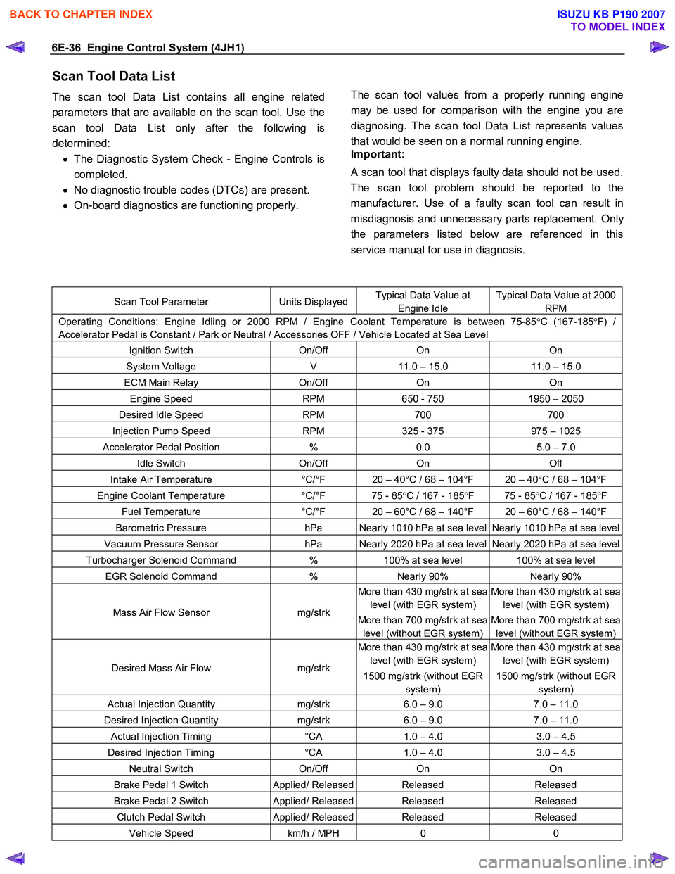
Scan Tool Data List
The scan tool Data List contains all engine related
parameters that are available on the scan tool. Use the
scan tool Data List only after the following is
determined: • The Diagnostic System Check - Engine Controls is
completed.
• No diagnostic trouble codes (DTCs) are present.
• On-board diagnostics are functioning properly.
The scan tool values from a properly running engine
may be used for comparison with the engine you are
diagnosing. The scan tool Data List represents values
that would be seen on a normal running engine.
Important:
A scan tool that displays faulty data should not be used.
The scan tool problem should be reported to the
manufacturer. Use of a faulty scan tool can result in
misdiagnosis and unnecessary parts replacement. Onl
y
the parameters listed below are referenced in this
service manual for use in diagnosis.
Scan Tool Parameter Units DisplayedTypical Data Value at
Engine Idle
Typical Data Value at 2000
RPM
Operating Conditions: Engine Idling or 2000 RPM / Engine Coolant Temperature is between 75-85 °C (167-185 °F) /
Accelerator Pedal is Constant / Park or Neutral / Accessories OFF / Vehicle Located at Sea Level
Ignition Switch On/Off On On
System Voltage V 11.0 – 15.0 11.0 – 15.0
ECM Main Relay On/Off On On
Engine Speed RPM 650 - 750 1950 – 2050
Desired Idle Speed RPM 700 700
Injection Pump Speed RPM 325 - 375 975 – 1025
Accelerator Pedal Position % 0.0 5.0 – 7.0
Idle Switch On/Off On Off
Intake Air Temperature °C/°F 20 – 40°C / 68 – 104°F 20 – 40°C / 68 – 104°F
Engine Coolant Temperature °C/°F 75 - 85 °C / 167 - 185 °F 75 - 85 °C / 167 - 185 °F
Fuel Temperature °C/°F 20 – 60°C / 68 – 140°F 20 – 60°C / 68 – 140°F
Barometric Pressure hPa Nearly 1010 hPa at sea level Nearly 1010 hPa at sea level
Vacuum Pressure Sensor hPa Nearly 2020 hPa at sea level Nearly 2020 hPa at sea level
Turbocharger Solenoid Command % 100% at sea level 100% at sea level
EGR Solenoid Command % Nearly 90% Nearly 90%
Mass Air Flow Sensor mg/strk
More than 430 mg/strk at sea
level (with EGR system)
More than 700 mg/strk at sea
level (without EGR system)
More than 430 mg/strk at sea
level (with EGR system)
More than 700 mg/strk at sea
level (without EGR system)
Desired Mass Air Flow mg/strk
More than 430 mg/strk at sea
level (with EGR system)
1500 mg/strk (without EGR
system)
More than 430 mg/strk at sea
level (with EGR system)
1500 mg/strk (without EGR
system)
Actual Injection Quantity mg/strk 6.0 – 9.0 7.0 – 11.0
Desired Injection Quantity mg/strk 6.0 – 9.0 7.0 – 11.0
Actual Injection Timing °CA 1.0 – 4.0 3.0 – 4.5
Desired Injection Timing °CA 1.0 – 4.0 3.0 – 4.5
Neutral Switch On/Off On On
Brake Pedal 1 Switch Applied/ ReleasedReleased Released
Brake Pedal 2 Switch Applied/ ReleasedReleased Released
Clutch Pedal Switch Applied/ ReleasedReleased Released
Vehicle Speed km/h / MPH 0 0
BACK TO CHAPTER INDEX
TO MODEL INDEX
ISUZU KB P190 2007
Page 1072 of 6020
6E-38 Engine Control System (4JH1)
Intake Air Temperature
This parameter displays the temperature of the intake
air based on a voltage input from the intake ai
r
temperature (IAT) sensor to the ECM. The scan tool will
display a low temperature when signal voltage is high,
and high temperature when the signal voltage is low.
Note that the IAT sensor is internal to the mass air flo
w
(MAF) sensor and the MAF sensor is heated.
Engine Coolant Temperature
This parameter displays the temperature of the engine
coolant based on a voltage input from the engine
coolant temperature (ECT) sensor to the ECM. The
scan tool will display a low temperature when the signal
voltage is high, and a high temperature when the signal
voltage is low.
Fuel Temperature
This parameter displays the temperature of the fuel as
calculated by the fuel injection pump control unit (PCU)
using the signal from the fuel temperature sensor inside
of the PCU.
Barometric Pressure
This parameter displays the barometric pressure as
calculated by the ECM using the signal from the
barometric pressure (BARO) sensor inside of the ECM.
Vacuum Pressure Sensor (High altitude
specification only)
This parameter displays the amount of the vacuum
pressure to the turbocharger wastegate valve. W hen a
high vacuum pressure at a low vacuum pressure
amount to the turbocharger wastegate valve. The scan
tool will display doubled barometric pressure when the
ignition is ON with the engine OFF.
Turbocharger Solenoid Command (High altitude
specification only)
This parameter displays the turbocharger solenoid
valuve control duty ratio commanded by the ECM
terminal (pin 96) using the signal from various senso
r
inputs. W hen a low duty ratio, vacuum pressure to the
turbocharger wastegate valve is controlled to increase.
W hen a high duty ratio, vacuum pressure to the
turbochager wastegate valve is controlled to reduce.
EGR Solenoid Command
This parameter displays the EGR solenoid valve control
duty ratio commanded by the ECM terminal (pin 97)
using the signal from engine speed, and injection
volume and various sensor inputs. W hen a small dut
y
ratio, the EGR valve is controlled to close. W hen a large
duty ratio, the EGR valve is controlled to open.
Mass Air Flow Sensor
This parameter displays the air flow into the engine as
calculated by the ECM based on the mass air flo
w
(MAF) sensor input. The scan tool will display a high
value at higher engine speeds, and a low value at idle.
This can be compared to the Desired Mass Air Flow to
determine MAF sensor accuracy, EGR problem o
r
intake problem. Note that the MAF on the scan tool will
only update with the engine running.
Desired Mass Air Flow
This parameter displays a mass air flow desired by the
ECM based on current driving condition.
Actual Injection Quantity
This parameter displays the injection quantity calculated
by the PCU based on the fuel injection solenoid valve
On time which compensated from the timing device
position and fuel temperature inputs. This can be
compared to the Desired Injection Quantity to determine
fuel system problem.
Desired Injection Quantity
This parameter displays an injection quantity desired b
y
the ECM based on current driving condition using target
injection maps.
Actual Injection Timing
This parameter displays the injection timing calculated
by the PCU based on the timing device position which
determined from the crankshaft position sensor and
camshaft position sensor inputs. This can be compared
to the Desired Injection Timing to determine timing
device problem or fuel system problem.
Desired Injection Timing
This parameter displays injection timing desired by the
ECM based on current driving condition using target
injection timing maps. This timing is compensated b
y
engine coolant temperature, altitude and intake ai
r
temperature, etc.
Neutral Switch
This parameter displays the state of the neutral switch
as determined by the ECM terminal (pin 87) based on
an input from the neutral switch or inhibitor switch.
Brake Pedal 1 Switch
This parameter displays the state of the brake pedal as
determined by the ECM terminal (pin 30) based on an
input from the brake pedal 1 switch. This switch turns
On the stop lamps when the brake pedal is depressed.
The scan tool will display Applied when the brake pedal
is depressed.
BACK TO CHAPTER INDEX
TO MODEL INDEX
ISUZU KB P190 2007
Page 1073 of 6020
Engine Control System (4JH1) 6E-39
Brake Pedal 2 Switch
This parameter displays the state of the brake pedal 2
switch as determined by the ECM terminal (pin 65). The
scan tool will display Released or Applied. Released
indicates the brake pedal is not being pushed down.
Applied indicates the brake switch is being depressed.
Clutch Pedal Switch (M/T Only)
This parameter displays the state of the clutch pedal as
determined by the ECM terminal (pin 31) based on an
input from the clutch pedal switch. The scan tool will
display Release or Applied. Release indicates the clutch
pedal is not being push down. Applied indicates the
clutch switch is being depressed.
Vehicle Speed
This parameter displays the vehicle speed calculated b
y
the ECM based on an input from the vehicle speed
sensor (VSS). The scan tool will display a high value at
higher vehicle speeds, and low value at lower vehicle
speeds.
Glow Relay Command
This parameter displays the commanded state of the
glow plug relay control circuit (pin 94). The scan tool will
display On or Off. On indicates the glow plug rela
y
control circuit is being grounded by the ECM, allowing
voltage to the glow plugs. Off indicates the glow plug
relay is not being commanded On by the ECM.
Glow Indicator Lamp Command
This parameter displays the commanded state of the
glow indicator lamp control circuit (pin 43). The glo
w
indicator lamp should be On when the scan tool
indicates On. The glow indicator should be Off when the
scan tool indicates Off.
Malfunction Indicator Lamp (MIL) Command
This parameter displays the commanded state of the
malfunction indicator lamp (MIL) control circuit (pin 42).
The MIL should be On when the scan tool indicates On.
The MIL should be Off when the scan tool indicates Off.
The ECM will command the MIL On for a certain length
of time when the ignition is On with the engine Off in
order to perform a bulb check.
A/C Request Signal
This parameter displays the state of the air conditioning
(A/C) request input to the ECM terminal (pin 33) from
the heating, ventilation, and air conditioning (HVAC)
controls. The scan tool will display On or Off. On
indicates the ECM is receiving a request from the HVAC
system to ground the A/C compressor relay control
circuit, engaging the
A/C compressor clutch. Off
indicates the ECM is not receiving a request from the
HVAC system.
A/C Relay Command
This parameter displays the commanded state of the
A/C compressor relay control circuit (pin 41). The scan
tool will display On or Off. On indicates the
A/C
compressor relay control circuit is being grounded b
y
the ECM, allowing voltage to the A/C compressor
clutch. Off indicates the A/C compressor relay is not
being commanded On by the ECM.
BACK TO CHAPTER INDEX
TO MODEL INDEX
ISUZU KB P190 2007
Page 1094 of 6020

6E-60 Engine Control System (4JH1)
DTC
(Symptom Code) Flash
Code MIL
Status DTC Name on
scan tool Condition for
Running the DTC Condition for
Setting the DTC Possible Cause
P0703
(B) 25 ON Brake Switch
Circuit •
The ignition switch
is ON.
• The engine speed
is higher than 665
RPM.
• The vehicle speed
is higher than 0
km/h (0 MPH).
•
The ECM detects
that the brake pedal
1 switch is OFF
(Released) when
the brake pedal 2
switch is ON
(Applied) for longer
than 30 seconds. •
Stop (15A) fuse (C-15) open.
• ECM (10A) fuse (EB-4) open.
• Brake pedal 1 switch battery
voltage feed circuit is open
circuit or high resistance.
• Brake pedal 1 switch signal
circuit is open circuit, high
resistance, short to battery or
ignition voltage.
• Brake pedal 2 switch ignition
voltage feed circuit is open
circuit or high resistance.
• Brake pedal 2 switch signal
circuit is open circuit, high
resistance, short to battery or
ignition voltage.
• Misadjusted brake pedal switch.
• Brake pedal switch is poor
connection.
• Faulty brake pedal switch.
• Faulty ECM.
P0704 (6) 57 ON Clutch Switch
Input Circuit •
The ignition switch
is ON.
•
The ECM detects
that the clutch pedal
switch signal does
not change during
the vehicle speed
changes between
1.5 km/h (1 MPH)
and 80 km/h (50
MPH).
•
ECM (10A) fuse (EB-4) open.
• Clutch pedal switch ignition
voltage feed circuit is open
circuit or high resistance.
• Clutch pedal switch signal circuit
is open circuit, high resistance,
short to battery or ignition
voltage.
• Misadjusted clutch pedal switch.
• Clutch pedal switch is poor
connection.
• Faulty clutch pedal switch.
• Faulty ECM.
P1105 (1) 86 ON Barometric
Pressure (BARO)
Sensor Circuit
High Voltage
•
The ignition switch
is ON.
•
The ECM detects
that the BARO
sensor signal
voltage is more
than 4.4 volts for 1
second.
•
Faulty ECM.
P1105
(2) 86 ON Barometric
Pressure (BARO)
Sensor Circuit Low
Voltage
•
The ignition switch
is ON.
•
The ECM detects
that the BARO
sensor signal
voltage is less than
1.5 volts for 1
second.
•
Faulty ECM.
BACK TO CHAPTER INDEX
TO MODEL INDEX
ISUZU KB P190 2007
Page 1095 of 6020

Engine Control System (4JH1) 6E-61
DTC
(Symptom Code) Flash
Code MIL
Status DTC Name on
scan tool Condition for
Running the DTC Condition for
Setting the DTC Possible Cause
P1120
(1) 21 ON Accelerator Pedal
Position (APP)
Sensor Circuit
High Voltage •
The ignition switch
is ON.
•
The ECM detects
that the APP sensor
signal voltage is
more than 4.5 volts
for 0.5 seconds. •
Sensor 5V reference circuit is
short to battery or ignition
voltage.
• Sensor 5V reference circuit is
short to ground or short to the
low reference circuit.
• Sensor signal circuit is short to
any 5V reference circuit, short to
battery or ignition voltage circuit.
• Sensor low reference circuit is
open circuit or high resistance.
• Poor harness connector
connection.
• Faulty APP sensor.
• Faulty ECM.
P1120 (7) 21 ON Accelerator Pedal
Position (APP)
Sensor Circuit 5V
Reference High
Voltage
•
The ignition switch
is ON.
•
The ECM detects
that the APP sensor
voltage supply
circuit is more than
5.2 volts for 0.5
seconds.
•
Sensor 5V reference circuit is
short to battery or ignition
voltage circuit.
• Faulty ECM.
P1120 (9) 21 ON Accelerator Pedal
Position (APP)
Sensor Circuit 5V
Reference Low
Voltage
•
The ignition switch
is ON.
•
The ECM detects
that the APP sensor
voltage supply
circuit is less than
4.6 volts for 0.5
seconds.
•
Sensor 5V reference circuit is
short to ground or short to the
low reference circuit.
• Faulty APP sensor.
• Faulty ECM.
P1120 (D) 21 ON
Accelerator Pedal
Position (APP)
Sensor Circuit
Correlation •
The ignition switch
is ON.
• The engine speed
is higher than 1700
RPM.
• The vehicle speed
is higher than 1.5
km/h (1 MPH).
•
The ECM detects
APP sensor angle
is stationary more
than 8.7%, then
brake pedal is
depressed for
longer than 2
seconds.
•
Brake pedal 1 switch signal
circuit is open circuit, high
resistance, short to battery or
ignition voltage.
• Accelerator pedal stuck.
• Intake throttle valve stuck.
• Intake throttle valve control cable
damaged, stuck or no free play.
• Misadjusted APP sensor.
• Faulty APP sensor.
• Misadjusted brake pedal switch.
• Faulty brake pedal switch.
• Faulty ECM.
P1120 (E) 21 ON Accelerator Pedal
Position (APP)
Sensor Circuit
Correlation •
The ignition switch
is ON. Either of following
condition is met.
• The ECM detects
APP sensor angle
is less than 0.35%,
then idle switch is
OFF for longer than
0.6 seconds.
OR
• The ECM detects
APP sensor angle
is more than 8.7%,
then idle switch is
ON for longer than
0.6 seconds.
•
APP sensor 5V reference circuit
is open circuit or high resistance.
•
APP sensor signal circuit is open
circuit, high resistance, short to
ground or short to the low
reference circuit.
• APP sensor low reference circuit
is high resistance.
• Idle switch signal circuit is open
circuit, high resistance, short to
ground, short to battery or
ignition voltage.
• Poor harness connector
connection.
• Faulty APP sensor.
• Faulty idle switch.
• Faulty ECM.
BACK TO CHAPTER INDEX
TO MODEL INDEX
ISUZU KB P190 2007