brake sensor ISUZU KB P190 2007 Workshop Repair Manual
[x] Cancel search | Manufacturer: ISUZU, Model Year: 2007, Model line: KB P190, Model: ISUZU KB P190 2007Pages: 6020, PDF Size: 70.23 MB
Page 4443 of 6020

TRANSMISSION CONTROL SYSTEM (JR405E) 7A2-159
Based on each transmission fluid pressure (TFP)
switch signal and each speed sensor signal and the
accelerator pedal angle, the duty cycle type shift
solenoid valve adjusts the clutch pressure to match the
engine load and vehicle running conditions. Controlling
the engagement and disengagement of the clutch and
brake pressure is directly and accurately controlled via
TCM, which is different to the conventional accumulator
type. Instead of the conventional system (On/ Off type
shift solenoid valve and shift valve), the combination of
the duty cycle type solenoid valve and the amplifier
(AMP) valve are used to adjust the clutch pressure to
match the engine load and vehicle driving conditions,
based on the signal from the TCM. Also, the TFP
switch provided in the fluid passage of the control valve
transmits to TCM, enabling the engagement and
disengagement control of the clutch and brake to be
directly and finely. When the gear is shifted from the
2nd to 3rd, 3rd to 4th, 4th to 3rd and 3rd to 2nd, the
clutch pressures on the engagement side and
disengagement side are simultaneously controlled. As
a result, engine racing or clutch drag is prevented
which enables a smooth and quick shift response.
Learning Control
Solenoid valve outputs
Low & reverse brake solenoid valve
2-4 brake solenoid valve
High clutch solenoid valve
Low clutch solenoid valve
TCM
Sensor inputs Input shaft speed (ISS) sensor
Output shaft speed (OSS) sensor
Transmission fluid temperature (TFT) sensor
Accelerator pedal position signal (via ECM)
Engine speed signal (via ECM)
Switch inputs
Low & reverse brake transmission fluid
pressure (TFP) switch
2-4 brake transmission fluid pressure (TFP)
switch
High clutch transmission fluid pressure (TFP)
switch
BACK TO CHAPTER INDEX
TO MODEL INDEX
ISUZU KB P190 2007
Page 4470 of 6020

7A3-16 ON-VEHICLE SERVICE (JR405E)
SOLENOIDS, OIL PRESSURE SWITCH AND OIL TEMPERATURE
SENSOR
244L300003
Legend
1. High clutch oil pressure switch connector
(wire color: Gray)
2. 2-4 brake oil pressure switch connector
(wire color: Brown)
3. Low and reverse brake oil pressure switch connector (wire color: W hite)
4. Low and reverse brake duty solenoid connector
(wire color: Pink and W hite)
5. High clutch duty solenoid connector
(wire color: Green and Gray)
6. Lock-up duty solenoid connector
(wire color: Yellow and Black)
7. 2-4 brake duty solenoid connector
(wire color: Blue and Brown)
8. Low clutch duty solenoid connector
(wire color: Orange and Black)
9. Line pressure solenoid connector
(wire color: Pink)
BACK TO CHAPTER INDEX
TO MODEL INDEX
ISUZU KB P190 2007
Page 4504 of 6020

UNIT REPAIR (JR405E) 7A4-27
Spring specifications
No. Valve nomenclature Free length
(mm / in) Outside
diameter
(mm / in) Linear
diameter
(mm / in) Number of
coils
14 Pressure relief 49.0 / 1.929 7.6 / 0.299 1.1 / 0.043 17.3
15 Pressure regulator 30.5 / 1.201 14.0 / 0.551 1.4 / 0.055 5.7
16 Low and reverse brake fail (A) 22.0 / 0.866 7.0 / 0.276 0.6 / 0.024 10.0
17 Fail 23.0 / 0.906 11.0 / 0.433 0.5 / 0.020 13.2
18 Low and reverse brake amp 19.5 / 0.768 7.9 / 0.311 0.5 / 0.020 6.9
19 2 – 4 brake fail (A) 24.8 / 0.976 8.5 / 0.335 0.9 / 0.035 7.8
20 Low clutch amp (B) 26.0 / 1.024 11.0 / 0.433 0.5 / 0.020 6.9
21
Torque converter relief More than 47.2
/ 1.858 9.2 / 0.362 1.6 / 0.063 20.2
22 2 – 4 brake solenoid accumulator 31.4 / 1.236 9.8 / 0.386 1.3 / 0.051 9.3
23 High clutch accumulator
51.0 / 2.008 6.5 / 0.256 0.8 / 0.031 23.5
Oil pressure switch
Apply compressed air (390 kPa/4.0 kgf/cm2/57 psi) to the oil
pressure switch to check the oil pressure switch continuity
between the connector and screw.
244L300011
Oil temperature sensor (harness assembly)
Check the oil temperature sensor resistance between harness
terminals 7 and 6 (ground).
Oil temperature sensor resistance: 2,400 ~
~~
~
2,600 ohms
(20 °
°°
°
C)
Solenoids
Measure the resistance of each solenoid.
Resistance:
Brown connector – 3.0 ∼
∼∼
∼
3.4 ohms (20 °
°°
°
C)
Gray connector – 12.0 ∼
∼∼
∼
13.2 ohms (20 °
°°
°
C)
White connector – 12.2 ∼
∼∼
∼
13.4 ohms (20 °
°°
°
C)
Reassembly steps
• Coat the parts with ATF before installing them.
• Install the control valve to the control valve lower body.
• Install the oil filter to the control valve lower body.
BACK TO CHAPTER INDEX
TO MODEL INDEX
ISUZU KB P190 2007
Page 5303 of 6020

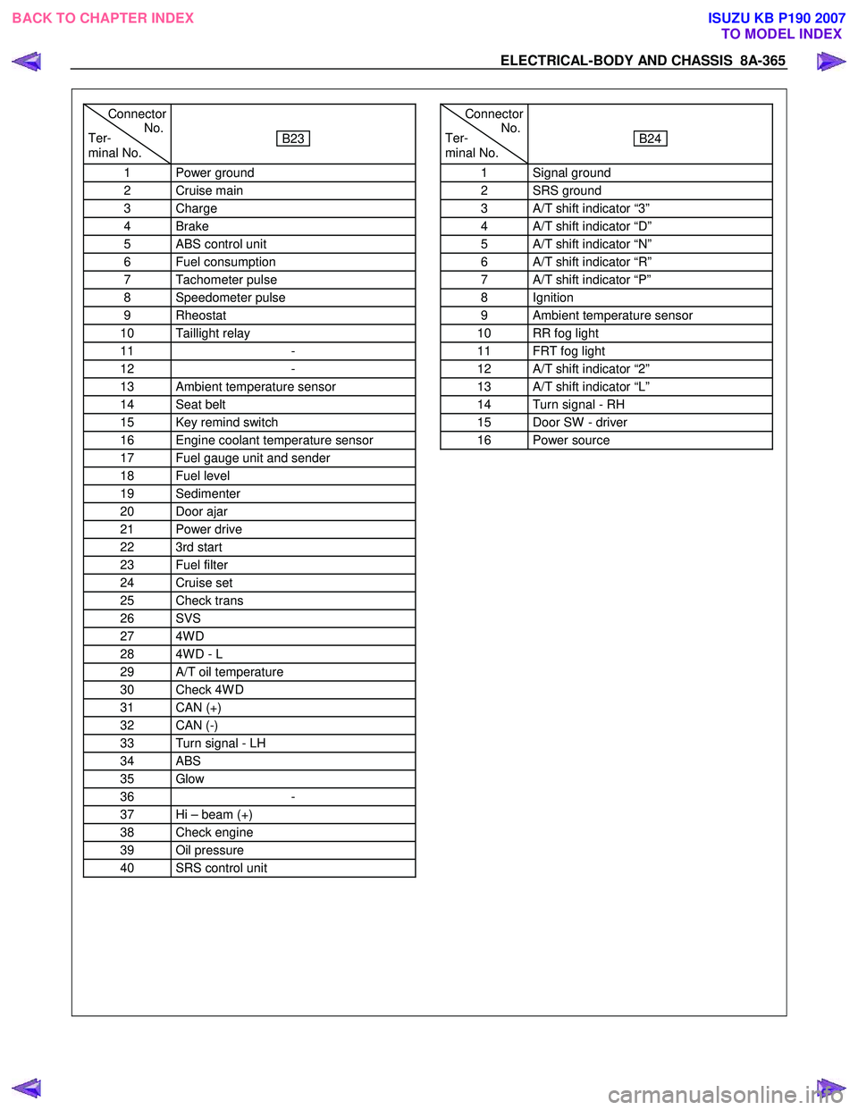
ELECTRICAL-BODY AND CHASSIS 8A-365
Connector
Ter- No.
minal No.
B23
1 Power ground
2 Cruise main
3 Charge
4 Brake
5 ABS control unit
6 Fuel consumption
7 Tachometer pulse
8 Speedometer pulse
9 Rheostat
10 Taillight relay
11 -
12 -
13 Ambient temperature sensor
14 Seat belt
15 Key remind switch
16 Engine coolant temperature sensor
17 Fuel gauge unit and sender
18 Fuel level
19 Sedimenter
20 Door ajar
21 Power drive
22 3rd start
23 Fuel filter
24 Cruise set
25 Check trans
26 SVS
27 4W D
28 4W D - L
29 A/T oil temperature
30 Check 4W D
31 CAN (+)
32 CAN (-)
33 Turn signal - LH
34 ABS
35 Glow
36 -
37 Hi – beam (+)
38 Check engine
39 Oil pressure
40 SRS control unit
Connector
Ter- No.
minal No.
B24
1 Signal ground
2 SRS ground
3 A/T shift indicator “3”
4 A/T shift indicator “D”
5 A/T shift indicator “N”
6 A/T shift indicator “R”
7 A/T shift indicator “P”
8 Ignition
9 Ambient temperature sensor
10 RR fog light
11 FRT fog light
12 A/T shift indicator “2”
13 A/T shift indicator “L”
14 Turn signal - RH
15 Door SW - driver
16 Power source
BACK TO CHAPTER INDEX TO MODEL INDEXISUZU KB P190 2007
Page 5304 of 6020

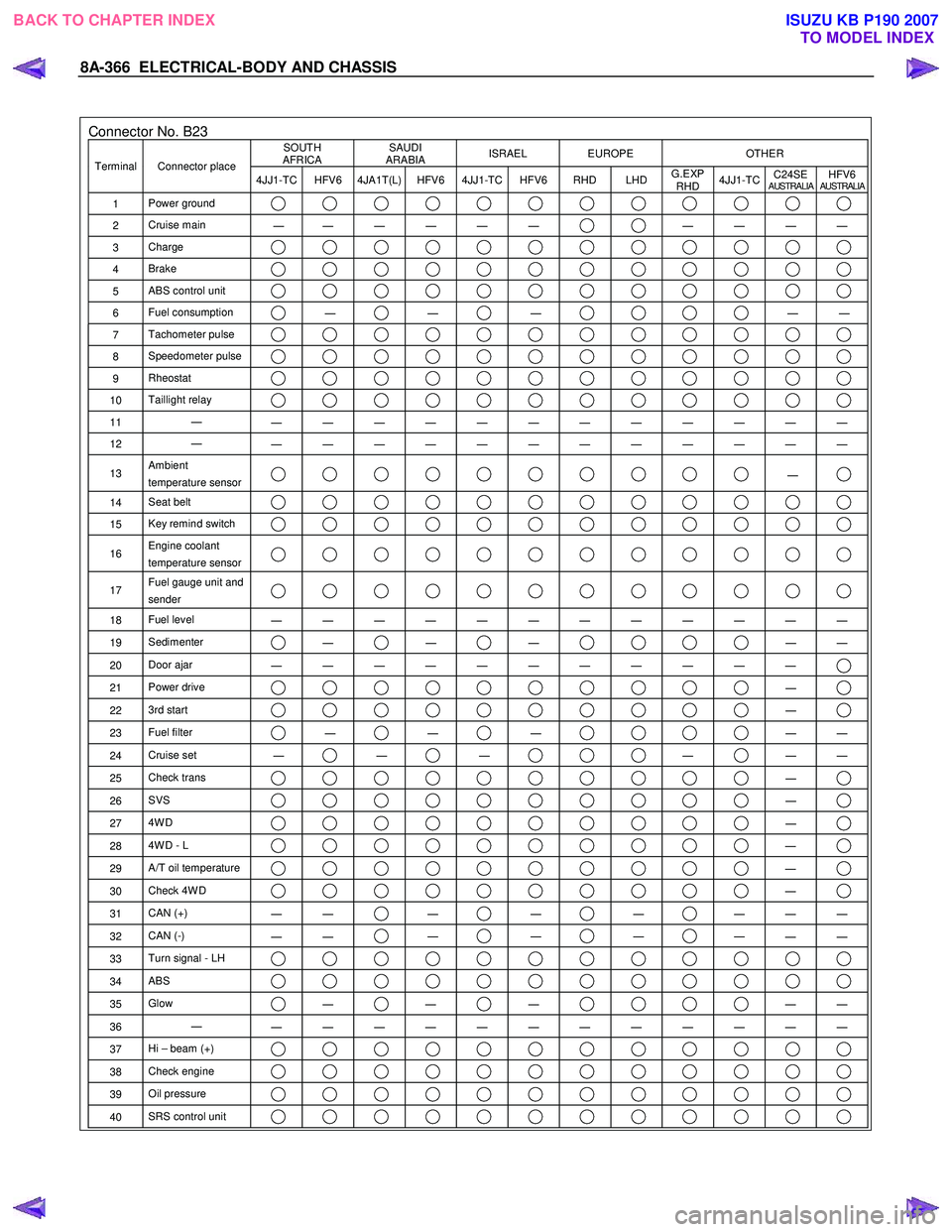
8A-366 ELECTRICAL-BODY AND CHASSIS
Connector No. B23 SOUTH
AFRICA SAUDI
ARABIA ISRAEL EUROPE OTHER
Terminal Connector place
4JJ1-TC HFV6 4JA1T(L) HFV6 4JJ1-TC HFV6 RHD LHD G.EXP
RHD 4JJ1-TC
C24SE
AUSTRALIAHFV6AUSTRALIA
1
Power ground
2 Cruise main
―
― ― ― ― ― ― ― ― ―
3
Charge
4 Brake
5 ABS control unit
6 Fuel consumption ―
―
―
―
―
7 Tachometer pulse
8 Speedometer pulse
9 Rheostat
10 Taillight relay
11 ―
― ― ― ― ― ― ― ― ― ― ― ―
12 ―
― ― ― ― ― ― ― ― ― ― ― ―
13 Ambient
temperature sensor ―
14 Seat belt
15 Key remind switch
16 Engine coolant
temperature sensor
17 Fuel gauge unit and
sender
18 Fuel level
― ― ― ― ― ― ― ― ― ― ― ―
19 Sedimenter ―
―
―
―
―
20 Door ajar
― ― ― ― ― ― ― ― ― ― ―
21 Power drive ―
22 3rd start ―
23 Fuel filter ―
―
―
―
―
24 Cruise set
― ―
―
―
―
―
25 Check trans ―
26 SVS ―
27 4W D ―
28 4W D - L ―
29 A/T oil temperature ―
30 Check 4W D ―
31 CAN (+)
― ― ―
―
―
― ― ―
32
CAN (-)
― ― ―
―
―
― ― ―
33
Turn signal - LH
34 ABS
35 Glow ―
―
―
―
―
36 ―
― ― ― ― ― ― ― ― ― ― ― ―
37 Hi – beam (+)
38 Check engine
39 Oil pressure
40 SRS control unit
BACK TO CHAPTER INDEX
TO MODEL INDEXISUZU KB P190 2007
Page 5307 of 6020

ELECTRICAL-BODY AND CHASSIS 8A-369
Low Fuel Indicator Light
1. Disconnect the fuel gauge unit wire connector.
2. Turn the key switch on. Check that the bulb lights.
If operation is not correct, remove and check the bulb or circuit.
or If check whether low fuel turns on fuel input (B-24) at the
time of open and key on.
∗ meter is check at low fuel
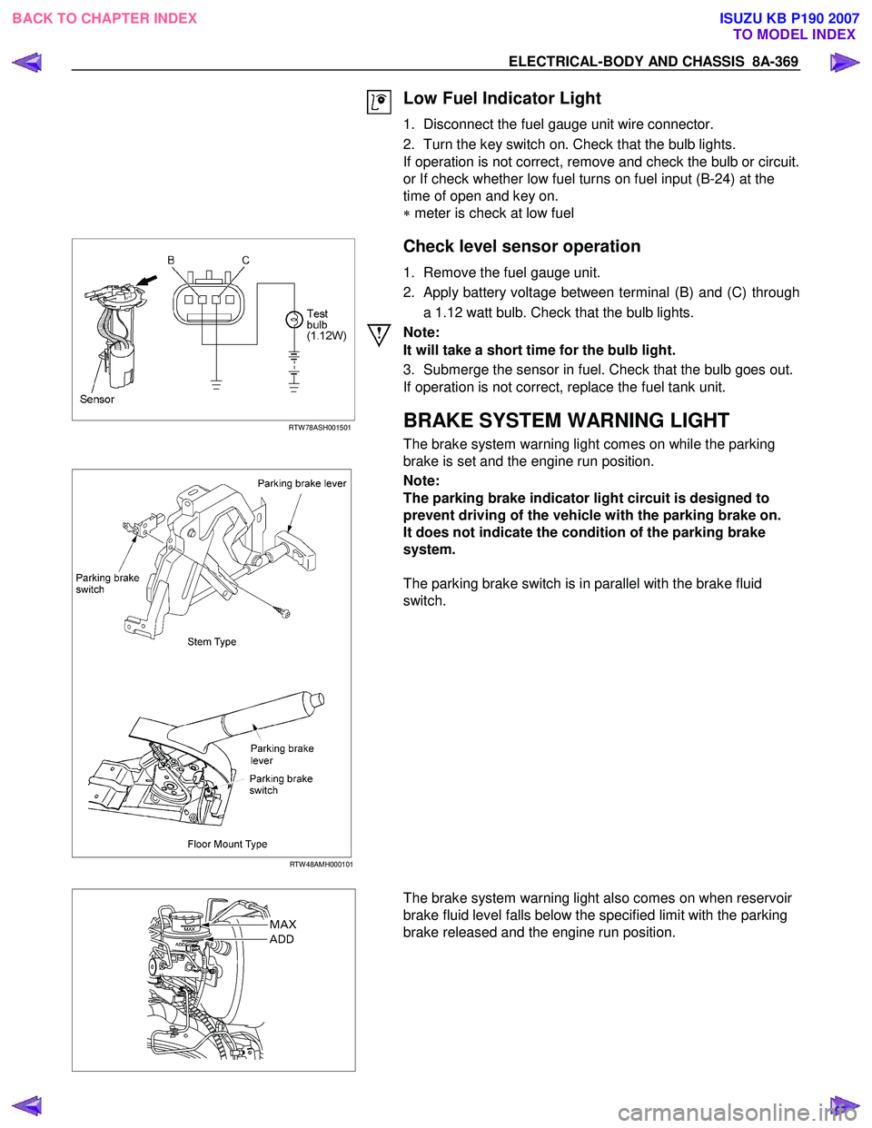
RTW 78ASH001501
Check level sensor operation
1. Remove the fuel gauge unit.
2. Apply battery voltage between terminal (B) and (C) through a 1.12 watt bulb. Check that the bulb lights.
Note:
It will take a short time for the bulb light.
3. Submerge the sensor in fuel. Check that the bulb goes out.
If operation is not correct, replace the fuel tank unit.
BRAKE SYSTEM WARNING LIGHT
The brake system warning light comes on while the parking
brake is set and the engine run position.
RTW 48AMH000101
Note:
The parking brake indicator light circuit is designed to
prevent driving of the vehicle with the parking brake on.
It does not indicate the condition of the parking brake
system.
The parking brake switch is in parallel with the brake fluid
switch.
The brake system warning light also comes on when reservoir
brake fluid level falls below the specified limit with the parking
brake released and the engine run position.
BACK TO CHAPTER INDEX TO MODEL INDEXISUZU KB P190 2007
Page 5550 of 6020

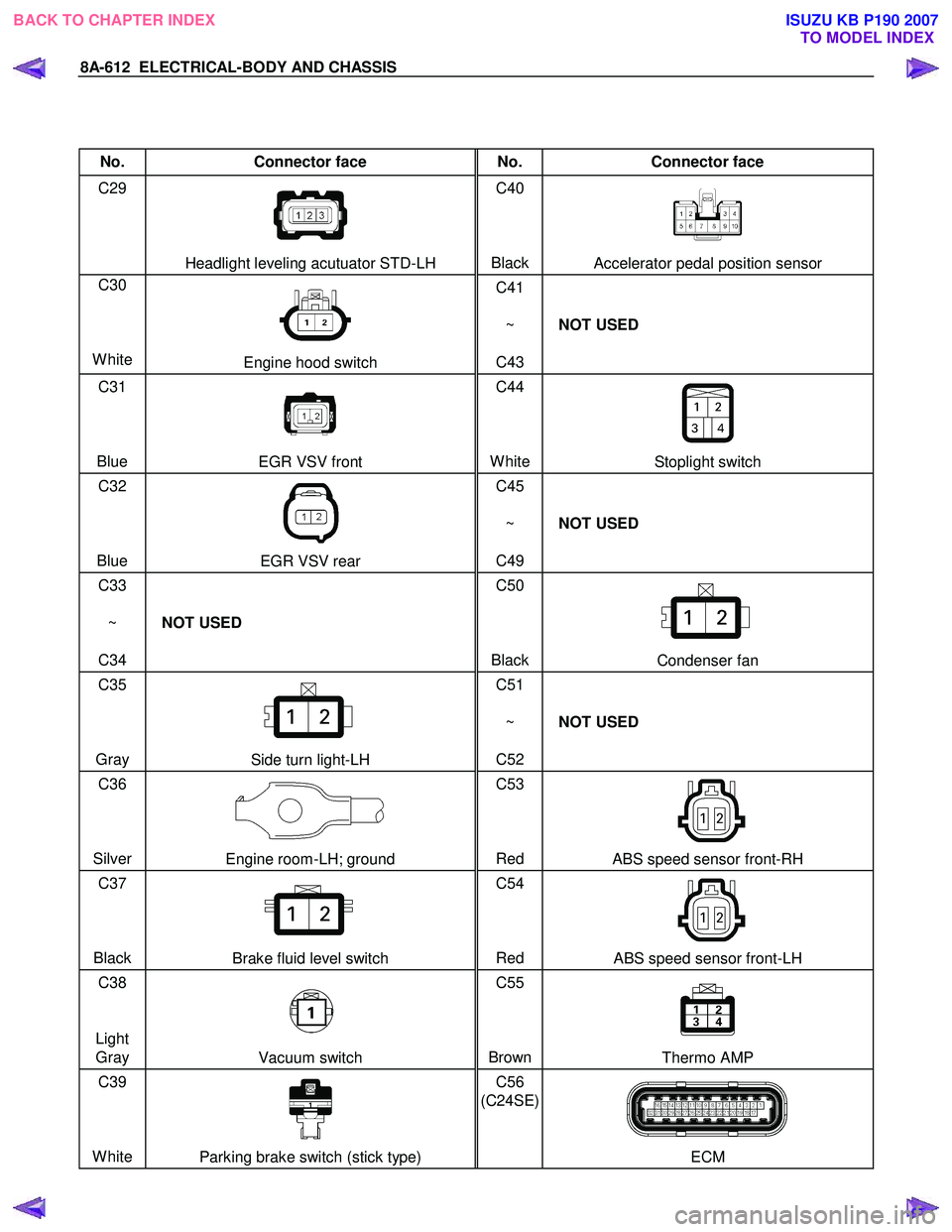
8A-612 ELECTRICAL-BODY AND CHASSIS
No. Connector face No. Connector face
C29
Headlight leveling acutuator STD-LH C40
BlackAccelerator pedal position sensor
C30
White
Engine hood switch C41
~
C43 NOT USED
C31
Blue
EGR VSV front C44
WhiteStoplight switch
C32
Blue
EGR VSV rear C45
~
C49 NOT USED
C33
~
C34 NOT USED C50
Black
Condenser fan
C35
Gray
Side turn light-LH C51
~
C52 NOT USED
C36
Silver
Engine room-LH; ground C53
Red ABS speed sensor front-RH
C37
Black
Brake fluid level switch C54
Red ABS speed sensor front-LH
C38
Light Gray
Vacuum switch C55
BrownThermo AMP
C39
White
Parking brake switch (stick type) C56
(C24SE)
ECM
BACK TO CHAPTER INDEX TO MODEL INDEXISUZU KB P190 2007
Page 5584 of 6020

Cruise Control – HFV6 Page 8C–6
The stop lamp switch contacts are normally open with the brake pedal at rest and close when the brake pedal is pressed
turning on the vehicles brake lamps. These switch contacts also double as the cruise cancel signal for the cruise control
operation.
The cruise control initial brake apply signal function switch contacts are normally closed with the brake pedal at rest and
open when the brake pedal is pressed. This switch function is a safety requirement of the vehicle as it ensures that the
cruise control cannot be activated without the brake pedal first being pressed.
Powertrain Interface Module
The Powertrain Interface Module (PIM) is located on the driver’s side, kick trim panel. The purpose of the PIM is to act as
an interface between the drivetrain serial data bus (GMLAN protocol) and the body side data bus (UART Bus protocol).
All inputs from the cruise control switch assembly are directly wired to the PIM. The PIM then takes these inputs,
converts them to GMLAN protocol and sends the messages via the data bus to the engine control module (ECM). The
PIM also receives signals for the cruise control system from the ECM. When the ECM activates cruise control, it sends a
signal through the PIM (which converts it from GMLAN to UART protocol) to display the various cruise control messages
on the instrument cluster assembly.
For further information on the operation of the PIM, refer to 6E1 Powertrain Interface Module – V6.
Engine Control Module
The Engine Control Module (ECM) is mounted on the front of the engine. The role of the ECM is to receive all the inputs
from various sensors (vehicle speed (VSS) etc.) and switches to manage the engine. W hen a request is sent from the
cruise control switch assembly via the PIM to the ECM, the ECM will activate cruise control providing given parameters
are satisfied. Once the cruise is set, the ECM monitors the vehicle speed and controls the throttle actuator assembly thus
controlling the speed of the vehicle.
For further information on the operation of the ECM, refer to 6C1-1 Engine Management – V6 – General Information.
Throttle Actuator Control (TAC) Assembly
The throttle actuator control assembly is located on the front of the inlet manifold. The throttle actuator control assembly
receives signals from the ECM and controls the angle of the throttle plate. Refer to 6C1-1 Engine Management – V6 –
General Information for further information.
1.3 System Operation
Preliminary Information
Enabled and Disabled
The cruise control is enabled / disabled by pressing the cruise control ON–OFF switch mounted on the lower right hand
side of the dash panel. When cruise control is enabled, the cruise control ON–OFF switch illuminates and the cruise
control is ready for a speed to be set (cruise control activated). W hen the cruise control is disabled, the cruise control
cannot be activated.
Cruise Enabled
1 The cruise control ON–OFF switch (1) supplies 12 Volts to the Powertrain Interface Module (PIM) when it
is pressed.
2 The cruise control ON–OFF switch lamp (2) turns on.
Cruise Disabled
1 W hen cruise control ON–OFF switch (1) is pressed again, power is removed from the PIM disabling the
cruise control.
2 The cruise control ON–OFF switch lamp (2) turns off.
Figure 8C – 4
BACK TO CHAPTER INDEX TO MODEL INDEXISUZU KB P190 2007