check engine ISUZU KB P190 2007 Workshop Repair Manual
[x] Cancel search | Manufacturer: ISUZU, Model Year: 2007, Model line: KB P190, Model: ISUZU KB P190 2007Pages: 6020, PDF Size: 70.23 MB
Page 3303 of 6020
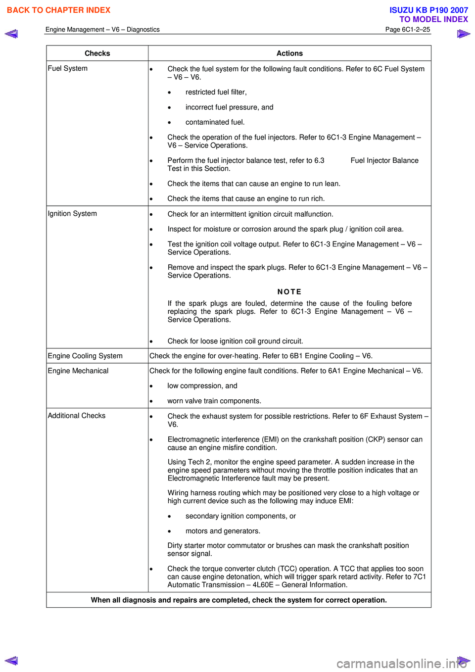
Engine Management – V6 – Diagnostics Page 6C1-2–25
Checks Actions
Fuel System
• Check the fuel system for the following fault conditions. Refer to 6C Fuel System
– V6 – V6.
• restricted fuel filter,
• incorrect fuel pressure, and
• contaminated fuel.
• Check the operation of the fuel injectors. Refer to 6C1-3 Engine Management –
V6 – Service Operations.
• Perform the fuel injector balance test, refer to 6.3 Fuel Injector Balance
Test in this Section.
• Check the items that can cause an engine to run lean.
• Check the items that cause an engine to run rich.
Ignition System
• Check for an intermittent ignition circuit malfunction.
• Inspect for moisture or corrosion around the spark plug / ignition coil area.
• Test the ignition coil voltage output. Refer to 6C1-3 Engine Management – V6 –
Service Operations.
• Remove and inspect the spark plugs. Refer to 6C1-3 Engine Management – V6 –
Service Operations.
NOTE
If the spark plugs are fouled, determine the cause of the fouling before
replacing the spark plugs. Refer to 6C1-3 Engine Management – V6 –
Service Operations.
• Check for loose ignition coil ground circuit.
Engine Cooling System Check the engine for over-heating. Refer to 6B1 Engine Cooling – V6.
Engine Mechanical Check for the following engine fault conditions. Refer to 6A1 Engine Mechanical – V6.
• low compression, and
• worn valve train components.
Additional Checks
• Check the exhaust system for possible restrictions. Refer to 6F Exhaust System –
V6.
• Electromagnetic interference (EMI) on the crankshaft position (CKP) sensor can
cause an engine misfire condition.
Using Tech 2, monitor the engine speed parameter. A sudden increase in the engine speed parameters without moving the throttle position indicates that an
Electromagnetic Interference fault may be present.
W iring harness routing which may be positioned very close to a high voltage or high current device such as the following may induce EMI:
• secondary ignition components, or
• motors and generators.
Dirty starter motor commutator or brushes can mask the crankshaft position sensor signal.
• Check the torque converter clutch (TCC) operation. A TCC that applies too soon
can cause engine detonation, which will trigger spark retard activity. Refer to 7C1
Automatic Transmission – 4L60E – General Information.
When all diagnosis and repairs are completed, check the system for correct operation.
BACK TO CHAPTER INDEX
TO MODEL INDEX
ISUZU KB P190 2007
Page 3304 of 6020
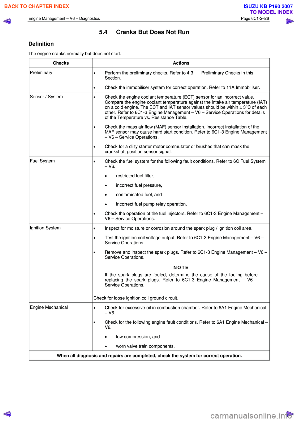
Engine Management – V6 – Diagnostics Page 6C1-2–26
5.4 Cranks But Does Not Run
Definition
The engine cranks normally but does not start.
Checks Actions
Preliminary • Perform the preliminary checks. Refer to 4.3 Preliminary Checks in this
Section.
• Check the immobiliser system for correct operation. Refer to 11A Immobiliser.
Sensor / System
• Check the engine coolant temperature (ECT) sensor for an incorrect value.
Compare the engine coolant temperature against the intake air temperature (IAT)
on a cold engine. The ECT and IAT sensor values should be within ± 3°C of each
other. Refer to 6C1-3 Engine Management – V6 – Service Operations for details
of the Temperature vs. Resistance Table.
• Check the mass air flow (MAF) sensor installation. Incorrect installation of the
MAF sensor may cause hard start condition. Refer to 6C1-3 Engine Management
– V6 – Service Operations.
• Check for a dirty starter motor commutator or brushes that can mask the
crankshaft position sensor signal.
Fuel System • Check the fuel system for the following fault conditions. Refer to 6C Fuel System
– V6.
• restricted fuel filter,
• incorrect fuel pressure,
• contaminated fuel, and
• incorrect fuel pump relay operation.
• Check the operation of the fuel injectors. Refer to 6C1-3 Engine Management –
V6 – Service Operations.
Ignition System • Inspect for moisture or corrosion around the spark plug / ignition coil area.
• Test the ignition coil voltage output. Refer to 6C1-3 Engine Management – V6 –
Service Operations.
• Remove and inspect the spark plugs. Refer to 6C1-3 Engine Management – V6 –
Service Operations.
NOTE
If the spark plugs are fouled, determine the cause of the fouling before
replacing the spark plugs. Refer to 6C1-3 Engine Management – V6 –
Service Operations.
Check for loose ignition coil ground circuit.
Engine Mechanical • Check for excessive oil in combustion chamber. Refer to 6A1 Engine Mechanical
– V6.
• Check for the following engine fault conditions. Refer to 6A1 Engine Mechanical –
V6.
• low compression, and
• worn valve train components.
When all diagnosis and repairs are completed, check the system for correct operation.
BACK TO CHAPTER INDEX
TO MODEL INDEX
ISUZU KB P190 2007
Page 3305 of 6020
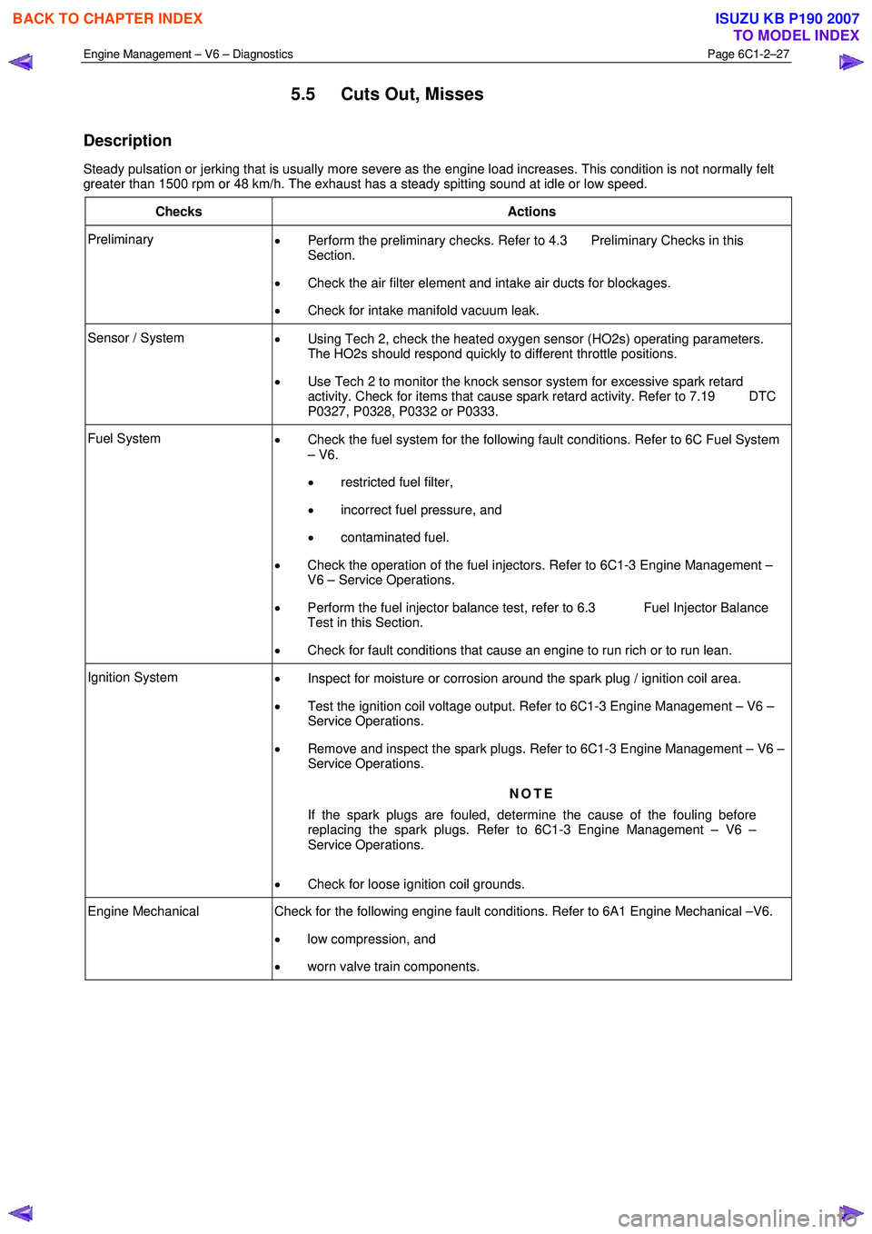
Engine Management – V6 – Diagnostics Page 6C1-2–27
5.5 Cuts Out, Misses
Description
Steady pulsation or jerking that is usually more severe as the engine load increases. This condition is not normally felt
greater than 1500 rpm or 48 km/h. The exhaust has a steady spitting sound at idle or low speed.
Checks Actions
Preliminary • Perform the preliminary checks. Refer to 4.3 Preliminary Checks in this
Section.
• Check the air filter element and intake air ducts for blockages.
• Check for intake manifold vacuum leak.
Sensor / System
• Using Tech 2, check the heated oxygen sensor (HO2s) operating parameters.
The HO2s should respond quickly to different throttle positions.
• Use Tech 2 to monitor the knock sensor system for excessive spark retard
activity. Check for items that cause spark retard activity. Refer to 7.19 DTC
P0327, P0328, P0332 or P0333.
Fuel System • Check the fuel system for the following fault conditions. Refer to 6C Fuel System
– V6.
• restricted fuel filter,
• incorrect fuel pressure, and
• contaminated fuel.
• Check the operation of the fuel injectors. Refer to 6C1-3 Engine Management –
V6 – Service Operations.
• Perform the fuel injector balance test, refer to 6.3 Fuel Injector Balance
Test in this Section.
• Check for fault conditions that cause an engine to run rich or to run lean.
Ignition System
• Inspect for moisture or corrosion around the spark plug / ignition coil area.
• Test the ignition coil voltage output. Refer to 6C1-3 Engine Management – V6 –
Service Operations.
• Remove and inspect the spark plugs. Refer to 6C1-3 Engine Management – V6 –
Service Operations.
NOTE
If the spark plugs are fouled, determine the cause of the fouling before
replacing the spark plugs. Refer to 6C1-3 Engine Management – V6 –
Service Operations.
• Check for loose ignition coil grounds.
Engine Mechanical Check for the following engine fault conditions. Refer to 6A1 Engine Mechanical –V6.
• low compression, and
• worn valve train components.
BACK TO CHAPTER INDEX
TO MODEL INDEX
ISUZU KB P190 2007
Page 3306 of 6020
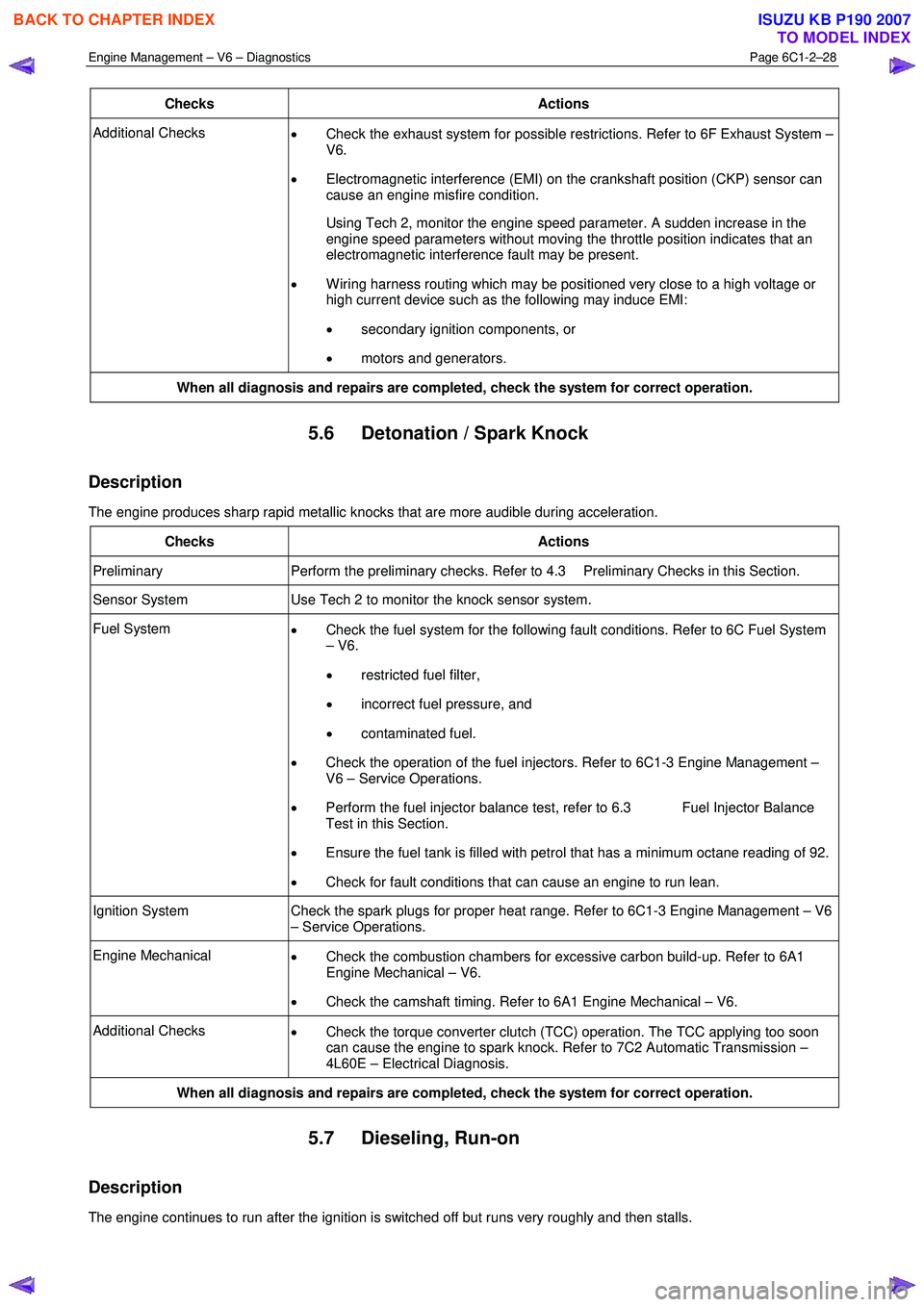
Engine Management – V6 – Diagnostics Page 6C1-2–28
Checks Actions
Additional Checks
• Check the exhaust system for possible restrictions. Refer to 6F Exhaust System –
V6.
• Electromagnetic interference (EMI) on the crankshaft position (CKP) sensor can
cause an engine misfire condition.
Using Tech 2, monitor the engine speed parameter. A sudden increase in the engine speed parameters without moving the throttle position indicates that an
electromagnetic interference fault may be present.
• W iring harness routing which may be positioned very close to a high voltage or
high current device such as the following may induce EMI:
• secondary ignition components, or
• motors and generators.
When all diagnosis and repairs are completed, check the system for correct operation.
5.6 Detonation / Spark Knock
Description
The engine produces sharp rapid metallic knocks that are more audible during acceleration.
Checks Actions
Preliminary Perform the preliminary checks. Refer to 4.3 Preliminary Checks in this Section.
Sensor System Use Tech 2 to monitor the knock sensor system.
Fuel System
• Check the fuel system for the following fault conditions. Refer to 6C Fuel System
– V6.
• restricted fuel filter,
• incorrect fuel pressure, and
• contaminated fuel.
• Check the operation of the fuel injectors. Refer to 6C1-3 Engine Management –
V6 – Service Operations.
• Perform the fuel injector balance test, refer to 6.3 Fuel Injector Balance
Test in this Section.
• Ensure the fuel tank is filled with petrol that has a minimum octane reading of 92.
• Check for fault conditions that can cause an engine to run lean.
Ignition System Check the spark plugs for proper heat range. Refer to 6C1-3 Engine Management – V6
– Service Operations.
Engine Mechanical • Check the combustion chambers for excessive carbon build-up. Refer to 6A1
Engine Mechanical – V6.
• Check the camshaft timing. Refer to 6A1 Engine Mechanical – V6.
Additional Checks
• Check the torque converter clutch (TCC) operation. The TCC applying too soon
can cause the engine to spark knock. Refer to 7C2 Automatic Transmission –
4L60E – Electrical Diagnosis.
When all diagnosis and repairs are completed, check the system for correct operation.
5.7 Dieseling, Run-on
Description
The engine continues to run after the ignition is switched off but runs very roughly and then stalls.
BACK TO CHAPTER INDEX
TO MODEL INDEX
ISUZU KB P190 2007
Page 3307 of 6020
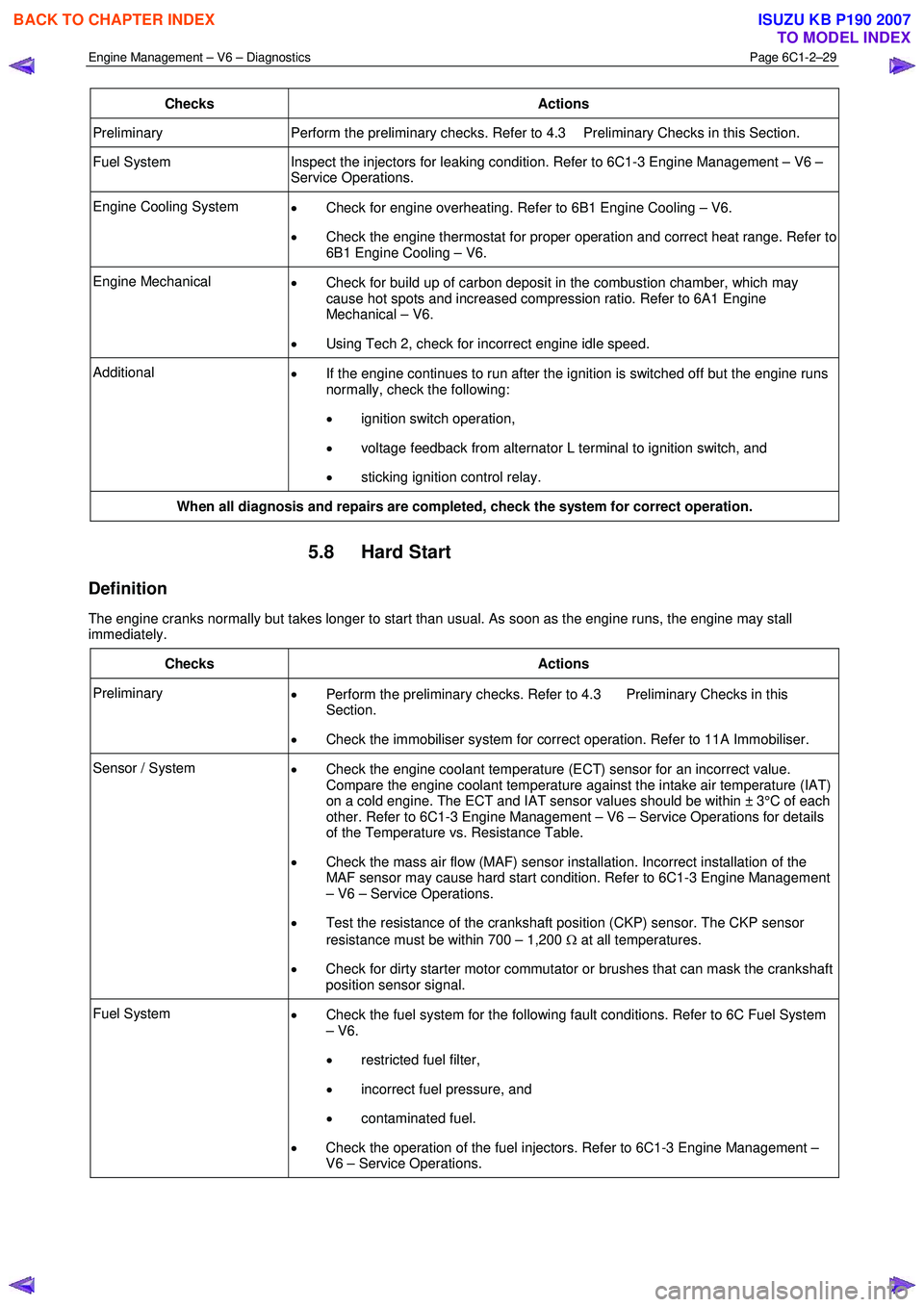
Engine Management – V6 – Diagnostics Page 6C1-2–29
Checks Actions
Preliminary Perform the preliminary checks. Refer to 4.3 Preliminary Checks in this Section.
Fuel System Inspect the injectors for leaking condition. Refer to 6C1-3 Engine Management – V6 –
Service Operations.
Engine Cooling System • Check for engine overheating. Refer to 6B1 Engine Cooling – V6.
• Check the engine thermostat for proper operation and correct heat range. Refer to
6B1 Engine Cooling – V6.
Engine Mechanical • Check for build up of carbon deposit in the combustion chamber, which may
cause hot spots and increased compression ratio. Refer to 6A1 Engine
Mechanical – V6.
• Using Tech 2, check for incorrect engine idle speed.
Additional
• If the engine continues to run after the ignition is switched off but the engine runs
normally, check the following:
• ignition switch operation,
• voltage feedback from alternator L terminal to ignition switch, and
• sticking ignition control relay.
When all diagnosis and repairs are completed, check the system for correct operation.
5.8 Hard Start
Definition
The engine cranks normally but takes longer to start than usual. As soon as the engine runs, the engine may stall
immediately.
Checks Actions
Preliminary • Perform the preliminary checks. Refer to 4.3 Preliminary Checks in this
Section.
• Check the immobiliser system for correct operation. Refer to 11A Immobiliser.
Sensor / System
• Check the engine coolant temperature (ECT) sensor for an incorrect value.
Compare the engine coolant temperature against the intake air temperature (IAT)
on a cold engine. The ECT and IAT sensor values should be within ± 3°C of each
other. Refer to 6C1-3 Engine Management – V6 – Service Operations for details
of the Temperature vs. Resistance Table.
• Check the mass air flow (MAF) sensor installation. Incorrect installation of the
MAF sensor may cause hard start condition. Refer to 6C1-3 Engine Management
– V6 – Service Operations.
• Test the resistance of the crankshaft position (CKP) sensor. The CKP sensor
resistance must be within 700 – 1,200 Ω at all temperatures.
• Check for dirty starter motor commutator or brushes that can mask the crankshaft
position sensor signal.
Fuel System • Check the fuel system for the following fault conditions. Refer to 6C Fuel System
– V6.
• restricted fuel filter,
• incorrect fuel pressure, and
• contaminated fuel.
• Check the operation of the fuel injectors. Refer to 6C1-3 Engine Management –
V6 – Service Operations.
BACK TO CHAPTER INDEX
TO MODEL INDEX
ISUZU KB P190 2007
Page 3308 of 6020

Engine Management – V6 – Diagnostics Page 6C1-2–30
Checks Actions
Ignition System
• Inspect for moisture or corrosion around the spark plug / ignition coil area.
• Test the ignition coil voltage output. Refer to 6C1-3 Engine Management – V6 –
Service Operations.
• Remove and inspect the spark plugs. Refer to 6C1-3 Engine Management – V6 –
Service Operations.
NOTE
If the spark plugs are fouled, determine the cause of the fouling before
replacing the spark plugs. Refer to 6C1-3 Engine Management – V6 –
Service Operations.
• Check for loose ignition coil ground circuit.
Engine Mechanical
• Check for excessive oil in combustion chamber. Refer to 6A1 Engine Mechanical
– V6.
• Check for the following engine fault conditions. Refer to 6A1 Engine Mechanical –
V6.
• low compression, and
• worn valve train components.
When all diagnosis and repairs are completed, check the system for correct operation.
5.9 Hesitation, Sag and Stumble
Description
Momentary lack of response or hesitation as the accelerator is depressed. This condition is usually more severe when
first trying to make the vehicle move from a standing start but can occur at any vehicle speed.
Checks Actions
Preliminary • Perform the preliminary checks. Refer to 4.3 Preliminary Checks in this
Section.
• Check the air filter element and intake air ducts for blockages.
Sensor / System
• Using Tech 2, check the heated oxygen sensor (HO2s) operating parameters.
The HO2s should respond quickly to different throttle positions.
• Inspect the accelerator pedal position (APP) sensor harness connector for correct
connection. Poor connection of this connector will not set a DTC.
Fuel System • Check the fuel system for the following fault conditions. Refer to 6C Fuel System
– V6.
• restricted fuel filter,
• incorrect fuel pressure, and
• contaminated fuel.
• Check the operation of the fuel injectors. Refer to 6C Fuel System – V6.
• Perform the fuel injector balance test, refer to 6.3 Fuel Injector Balance
Test in this Section.
• Check for fault conditions that cause an engine to run rich or to run lean.
BACK TO CHAPTER INDEX
TO MODEL INDEX
ISUZU KB P190 2007
Page 3309 of 6020

Engine Management – V6 – Diagnostics Page 6C1-2–31
Checks Actions
Ignition System
• Inspect for moisture or corrosion around the spark plug / ignition coil area.
• Test the ignition coil voltage output. Refer to 6C1-3 Engine Management – V6 –
Service Operations.
• Remove and inspect the spark plugs. Refer to 6C1-3 Engine Management – V6 –
Service Operations.
NOTE
If the spark plugs are fouled, determine the cause of the fouling before
replacing the spark plugs. Refer to 6C1-3 Engine Management – V6 –
Service Operations.
• Check for loose ignition coil ground circuit.
Engine Cooling System Check the engine thermostat for correct operation and heat range. Refer to 6B1 Engine
Cooling – V6.
Additional Checks • Check the generator output voltage. Refer to 6D1-1 Charging System – V6.
When all diagnosis and repairs are completed, check the system for correct operation.
5.10 Lack of Power, Sluggishness or
Sponginess
Description
The engine delivers less than normal power. There is little or no increase in vehicle speed when the accelerator pedal is
partially depressed.
Checks Actions
Preliminary • Perform the preliminary checks. Refer to 4.3 Preliminary Checks in this
Section.
• Check the air filter element and intake air ducts for blockages.
Sensor / System
• Use Tech 2 to monitor the knock sensor system for excessive spark retard
activity. Check for items that cause spark retard activity.
• Inspect the accelerator pedal position (APP) sensor harness connector for correct
connection. Poor connection of this connector will not set a DTC.
Fuel System • Check the fuel system for the following fault conditions. Refer to 6C Fuel System
– V6.
• restricted fuel filter,
• incorrect fuel pressure, and
• contaminated fuel.
• Check the operation of the fuel injectors. Refer to 6C1-3 Engine Management –
V6 – Service Operations.
• Perform the fuel injector balance test, refer to 6.3 Fuel Injector Balance
Test in this Section.
• Check for fault conditions that can cause the engine to run rich or run lean.
BACK TO CHAPTER INDEX
TO MODEL INDEX
ISUZU KB P190 2007
Page 3310 of 6020
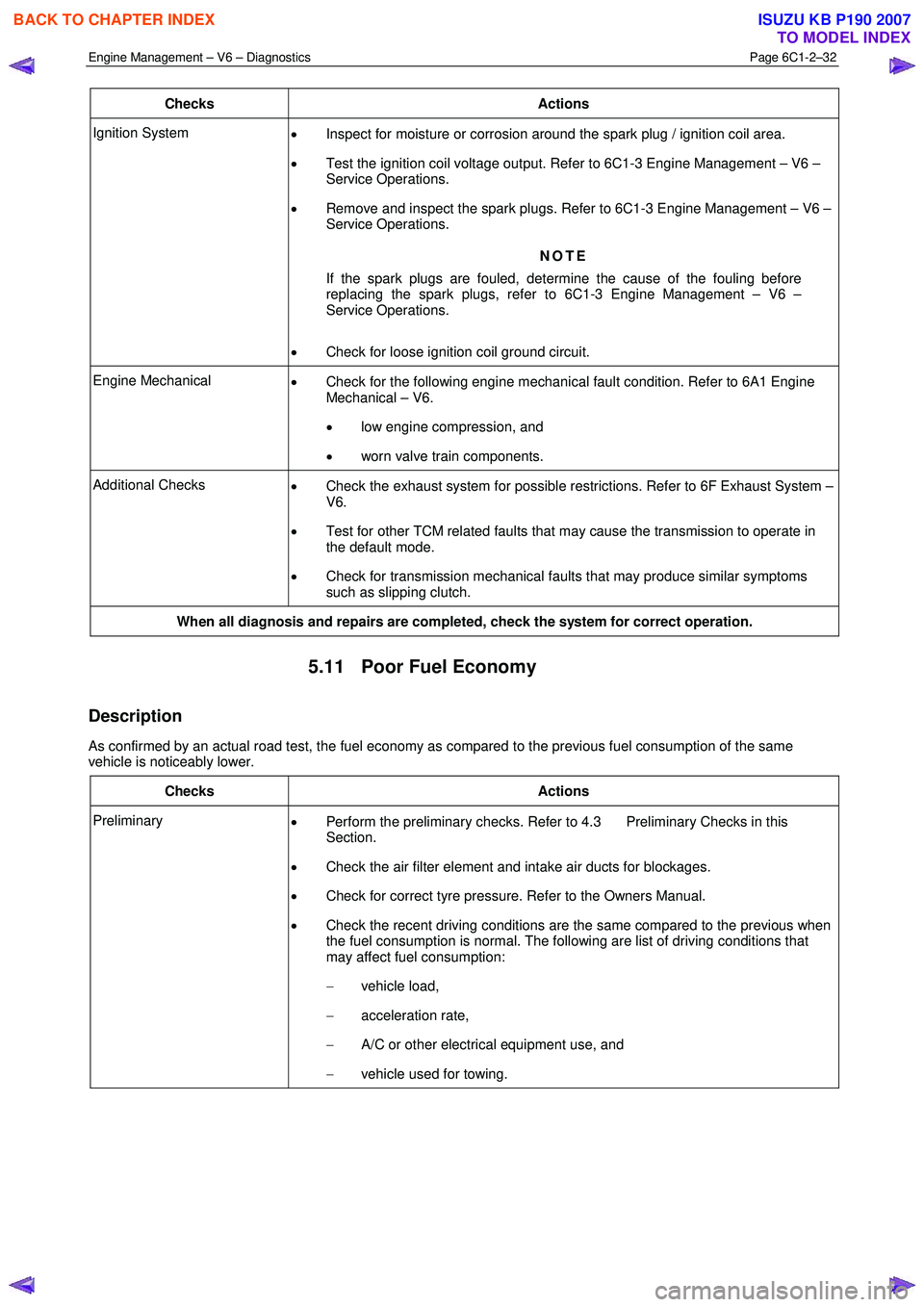
Engine Management – V6 – Diagnostics Page 6C1-2–32
Checks Actions
Ignition System
• Inspect for moisture or corrosion around the spark plug / ignition coil area.
• Test the ignition coil voltage output. Refer to 6C1-3 Engine Management – V6 –
Service Operations.
• Remove and inspect the spark plugs. Refer to 6C1-3 Engine Management – V6 –
Service Operations.
NOTE
If the spark plugs are fouled, determine the cause of the fouling before
replacing the spark plugs, refer to 6C1-3 Engine Management – V6 –
Service Operations.
• Check for loose ignition coil ground circuit.
Engine Mechanical
• Check for the following engine mechanical fault condition. Refer to 6A1 Engine
Mechanical – V6.
• low engine compression, and
• worn valve train components.
Additional Checks
• Check the exhaust system for possible restrictions. Refer to 6F Exhaust System –
V6.
• Test for other TCM related faults that may cause the transmission to operate in
the default mode.
• Check for transmission mechanical faults that may produce similar symptoms
such as slipping clutch.
When all diagnosis and repairs are completed, check the system for correct operation.
5.11 Poor Fuel Economy
Description
As confirmed by an actual road test, the fuel economy as compared to the previous fuel consumption of the same
vehicle is noticeably lower.
Checks Actions
Preliminary • Perform the preliminary checks. Refer to 4.3 Preliminary Checks in this
Section.
• Check the air filter element and intake air ducts for blockages.
• Check for correct tyre pressure. Refer to the Owners Manual.
• Check the recent driving conditions are the same compared to the previous when
the fuel consumption is normal. The following are list of driving conditions that
may affect fuel consumption:
− vehicle load,
− acceleration rate,
− A/C or other electrical equipment use, and
− vehicle used for towing.
BACK TO CHAPTER INDEX
TO MODEL INDEX
ISUZU KB P190 2007
Page 3311 of 6020

Engine Management – V6 – Diagnostics Page 6C1-2–33
Checks Actions
Sensor / System
• Check the air intake system and crankcase for air leaks.
• Check the PCV System for correct operation. Refer to 6A1 Engine Mechanical –
V6.
• Check for the correct calibration of the speedometer. Refer to 8A Electrical-Body.
• Use Tech 2 to monitor the knock sensor system for excessive spark retard
activity. Check for items that cause spark retard activity.
• Using Tech 2, check the heated oxygen sensor (HO2s) operating parameters.
The HO2s should respond quickly to different throttle positions.
Fuel System • Check the fuel system for the following fault conditions. Refer to 6C Fuel System
– V6.
− restricted fuel filter,
− incorrect fuel pressure, and
− contaminated fuel.
• Check the operation of the fuel injectors. Refer to 6C1-3 Engine Management –
V6 – Service Operations.
• Perform the fuel injector balance test, refer to 6.3 Fuel Injector Balance
Test in this Section.
• Check the items that cause an engine to run rich.
• Check for foreign material accumulation in the throttle bore, carbon build-up on
the throttle valve or on the throttle shaft.
• Check the throttle body for tampering.
Ignition System
• Inspect for moisture or corrosion around the spark plug / ignition coil area.
• Test the ignition coil voltage output. Refer to 6C1-3 Engine Management – V6 –
Service Operations.
• Remove and inspect the spark plugs. Refer to 6C1-3 Engine Management – V6 –
Service Operations.
NOTE
If the spark plugs are fouled, determine the cause of the fouling before
replacing the spark plugs. Refer to 6C1-3 Engine Management – V6 –
Service Operations.
• Check for loose ignition coil ground circuit.
Engine Cooling System
• Check the engine thermostat for proper operation and correct heat range. Refer to
6B1 Engine Cooling – V6.
Engine Mechanical Check for the following engine fault conditions. Refer to 6A1 Engine Mechanical – V6.
• low compression, and
• worn valve train components.
BACK TO CHAPTER INDEX
TO MODEL INDEX
ISUZU KB P190 2007
Page 3312 of 6020

Engine Management – V6 – Diagnostics Page 6C1-2–34
Checks Actions
Additional Checks
• Check the exhaust system for possible restrictions. Refer to 6F Exhaust System –
V6.
• Electromagnetic interference (EMI) on the crankshaft position (CKP) sensor can
cause an engine misfire condition.
Using Tech 2, monitor the engine speed parameter. A sudden increase in the engine speed parameters without moving the throttle position indicates that an
Electromagnetic Interference fault may be present.
W iring harness routing which may be positioned very close to a high voltage or high current device such as the following may induce EMI:
• secondary ignition components, and
• motors and generators.
• Check the torque converter clutch (TCC) operation. A TCC that applies too soon
can cause engine detonation, which will trigger spark retard activity. Refer to 7C2
Automatic Transmission – 4L60E – Electrical Diagnosis.
• Test for other TCM related faults that may cause the transmission to operate in
the default mode. Refer to 7C2 Automatic Transmission – 4L60E – Electrical
Diagnosis.
• Check for transmission mechanical faults such as slipping clutch. Refer to 7C3
Automatic Transmission – 4L60E – Hydraulic and Mechanical Diagnosis.
• Check the brake system including the parking brake for sticking or incorrect
operation.
When all diagnosis and repairs are completed, check the system for correct operation.
5.12 Rough, Unstable, Incorrect Idle or
Stalling
Description
Engine idle speed fluctuates causing the engine to run unevenly. If the engine idle speed drops too low, the engine may
stall.
Checks Actions
Preliminary • Perform the preliminary checks. Refer to 4.3 Preliminary Checks in this
Section.
• Check the air filter element and intake air ducts for blockages.
Sensor / System
• Check the throttle actuator control (TAC) system. Refer to 6C1-3 Engine
Management – V6 – Service Operations.
• Check the air intake system and crankcase for air leaks. Refer to 6C1-3 Engine
Management – V6 – Service Operations.
• Check the PCV System for correct operation. Refer to 6A1 Engine Mechanical –
V6.
• Use Tech 2 to monitor the knock sensor system for excessive spark retard
activity. Check for items that cause spark retard activity.
• Using Tech 2, check the heated oxygen sensor (HO2s) operating parameters.
The HO2s sensor should respond quickly to different throttle positions.
BACK TO CHAPTER INDEX
TO MODEL INDEX
ISUZU KB P190 2007