check engine ISUZU KB P190 2007 Workshop Repair Manual
[x] Cancel search | Manufacturer: ISUZU, Model Year: 2007, Model line: KB P190, Model: ISUZU KB P190 2007Pages: 6020, PDF Size: 70.23 MB
Page 3196 of 6020
Engine Cooling – V6 Engine Page 6B1–61
4 Engine Cooling System
Diagnosis
4.1 Poor Heater Operation
Little or no heat coming from the heater, especially at idle could be an indication of a cooling system problem.
As the coolant level begins to get lower than normal, air enters the system to replace the missing coolant. The heater
core is one of the highest parts of the cooling system and therefore, the first area to lose coolant circulation.
At first, with a small amount of coolant loss, lack of heat will be most noticeable at idle. As driving speed increases, the
engine pumps more coolant and more heat is now able to pass through the heater core.
If coolant level drops even lower, heater operation will become less effective, even during normal driving. Cooling and
engine systems can be adversely affected if problem is not corrected before overheating occurs.
4.2 Leaking Cylinder Head Gasket
Combustion gases leaking past the cylinder head gasket can pressurise the cooling system, forcing coolant out of the
system and into the coolant recovery reservoir.
Indications are air bubbles in the coolant or an overflow condition of the recovery reservoir.
4.3 Question the Customer
To avoid needless time and cost in diagnosing cooling system complaints, the customer should be questioned about
driving conditions that place abnormal loads on the cooling system.
1 Is overheating occurring after prolonged idle, in gear, with air conditioning system operating?
If answer is YES – instruct owner on driving techniques that would avoid overheating such as:
• Idle in neutral as much as possible – increase engine rpm to get higher air flow (due to an increase in voltage
to the fan) and coolant flow through the radiator
• Turn air conditioning system off during extended idling periods if overheating is indicated on temperature
gauge. Further diagnostic checks should not be required
2 Is overheating occurring after prolonged driving in slow city traffic, traffic jams, parades, etc?
If answer is YES, explain driving technique to the customer, that would avoid overheating – same as for prolonged idle – No.1. Further diagnostic checks should not be required.
4.4 Diagnostic Chart
If none of the above conditions apply, refer to the following Diagnosis Chart.
To effectively use this chart, question the customer to determine which of the following three categories apply to the
complaint:
1 If complaint is hot indication on temperature gauge.
W as temperature reading accompanied by boiling?
• If answer is YES, go to overheating on diagnosis chart
• If answer is NO, check temperature gauge and sender
2 If complaint is boiling – go to overheating on diagnosis chart.
3 If complaint is coolant loss. Determine if customer is filling the system correctly.
4 If incorrect filling is not the problem, go to coolant loss in the diagnosis chart.
BACK TO CHAPTER INDEX
TO MODEL INDEX
ISUZU KB P190 2007
Page 3197 of 6020

Engine Cooling – V6 Engine Page 6B1–62
Refer to 3.1 Service Notes in this Section, for
important safety items before removing the
coolant filler pressure cap or servicing the
system.
The cooling system is designed to operate at
120 –
––
–
130 kPa and a maximum temperature
not above 130 °
°°
°
C.
Cooling System Diagnosis
Step Action Result Yes No
1
Check Temperature gauge reading High Temp.
Low Temp. Go to Step 2
Go to Step 6 –
2
Check drive belt condition and tension. Refer to 6A1
Engine Mechanical. To Specification Go to Step 3 Replace drive
belt or
tensioner.
3 Check coolant Boiling Go to Step 4 Go to Step 5
4 Check coolant level. Refer to 3.2 Coolant
Maintenance in this Section. Low Go to Step 10 Go to Step 6
5
Check coolant filler cap. Refer to 3.7 Pressure
Testing – Coolant Filler Cap Pressure Testing in this
Section OK? Go to Step 8
Replace
Coolant filler
cap
6 Check thermostat. Refer to 3.8 Thermostat in this
Section. OK? Go to Step 9 Go to Step 13
7
Check Engine Coolant Temperature (ECT) sensor.
Refer to 6C1 Engine Management General Information. Faulty Replace Go to Step 12
8
Check cooling fan operation. Refer to 6C1 Engine
Management General Information. Operational Go to Step 10 Repair
9
Check for collapsed upper or lower radiator hose. Collapsed Replace Go to Step 13
10 Visual system check Leaks Go to Step 13 Go to Step 11
11 Check coolant concentration. Refer to 3.2 Coolant
Maintenance. To Specification Go to Step 12 Correct
Concentration Level
12 Check radiator core for bent fins, dirt, bugs or other
obstructions. Obstructed Clean or
straighten Go to Step 14
13
Pressure Test cooling system. Refer to 3.7 Pressure
Testing in this Section. Leaks Repair System OK
14
If none of the above require repair, the problem is
complex or of a major nature.
Refer to 4.5 Problems Not Requiring Disassembly of
Cooling System or 4.6 Problems Requiring Disassembly
of Cooling System. – – –
BACK TO CHAPTER INDEX
TO MODEL INDEX
ISUZU KB P190 2007
Page 3198 of 6020
Engine Cooling – V6 Engine Page 6B1–63
4.5 Problems Not Requiring Disassembly of
Cooling System
1 Large obstructions blocking radiator or condenser airflow.
• Auxiliary oil coolers
• License plate
• Obstruction of radiator grille, for example, driving lights or mud
2 Loose, damaged or missing air chute side panels.
3 Missing or damaged air baffle.
4 Cracked or loose coolant recovery system hose.
5 Leaking heater component such as the heater core or water valve.
4.6 Problems Requiring Disassembly of Cooling System
1 Damaged cooling fan or faulty motor operation.
2 Pressure test cooling system.
3 Defective coolant pump.
• Eroded or broken impeller vanes
• Failed bearing or seal – check for shaft or bearing end play
4 Internally blocked radiator core.
5 Obstruction of coolant recovery system.
6 Internal system leaks.
• Head gaskets
• Cracked cylinder block
• Engine front cover
• Intake manifold gaskets
7 Blocked coolant passages in cylinder heads or block – remove cylinder heads and check.
4.7 Black Light and Dye Leak Diagnosis Method
It is strongly recommended that this diagnostic method be used to diagnose fluid leaks. This method is a proven and
reliable method that identifies the specific leak source.
The black light kit can be used for the leak detection of a number of fluids, when used with the appropriate tracer dye.
Examples are: Coolant, Engine Oil, Automatic Transmission Fluid and Air Conditioning Refrigerant (R134A).
The following is a summary of the steps involved in detecting a cooling system fluid leak using black light and dye:
1 Pour specified amount of dye into the cooling system via the coolant filler cap on the outlet housing. Refer 3.1 Service Notes in this Section.
2 Road test the vehicle under normal operating conditions.
3 Direct the light towards the suspect area. The fluid leak will appear as a brightly coloured path leading from the source.
4 Repair fluid leak and recheck to ensure that leak has been rectified.
5 Refer to the manufacturer’s directions when using this method.
BACK TO CHAPTER INDEX
TO MODEL INDEX
ISUZU KB P190 2007
Page 3202 of 6020
Engine Cooling – V6 Engine Page 6B1–67
7 Special Tools
Tool number Illustration Description Classification
AU505
Coolant Tester
Used for testing the coolant
concentration level.
Previously released. Mandatory
AU525
Quick Connect Release Tool
Used to release the quick connect
fittings on automatic transmission fluid
cooler lines at the radiator end, when
fitted.
Previously released. Mandatory
BT3373–F
Belt Tension Gauge
Used when checking drive and
accessory belt tension and
adjustments.
Previously released. Desirable
J 26568 Refractometer
Used for testing coolant concentration
level.
Previously released, as AU 435. Mandatory
J28431–B Fluid Dye
Available in 24 x 1-ounce bottles.
Used in conjunction with a black light
such as J42220 to locate the source
of various fluid leaks.
Previously released. Desirable
J42220 Black Light, Leak Detection Lamp
Used with dye, J28431–B to locate the
source of various vehicle fluid leaks.
Previously released. Desirable
N/A Cooling System Pressure Tester
Previously released. Commercially available. Mandatory
BACK TO CHAPTER INDEX
TO MODEL INDEX
ISUZU KB P190 2007
Page 3204 of 6020
Fuel System – V6 Page 6C – 2
4.6 Evaporative Emission Control Canister............................................................................................................. 27
Remove ................................................................................................................................................................. 27
Service Check .................................................................................................................. .................................... 28
Reinstall ................................................................................................................................................................ 29
4.7 Fuel Tank Siphon Procedure ..................................................................................................... ......................... 30
4.8 Fuel Filler Cap ...................................................................................................................................................... 32
Remove ................................................................................................................................................................. 32
Inspection ......................................................................................................................................................... 32
Reinstall ................................................................................................................................................................ 32
4.9 Fuel Lines ..................................................................................................................... ........................................ 33
Remove ................................................................................................................................................................. 33
Fuel Tank Lines ................................................................................................................ .................................... 34
Reinstall ................................................................................................................................................................ 34
Fuel Line Routing.............................................................................................................. ................................... 35
Bell Housing Fuel Lines ........................................................................................................ .............................. 36
Engine Bay Fuel Lines......................................................................................................................................... 36
4.10 Rollover Valve ...................................................................................................................................................... 37
5 Specifications .......................................................................................................................................38
6 Torque Wrench Specifications................................................................................................... .........39
7 Special Tools ........................................................................................................................................40
BACK TO CHAPTER INDEX
TO MODEL INDEX
ISUZU KB P190 2007
Page 3210 of 6020

Fuel System – V6 Page 6C – 8
3 System Checks
3.1 Fuel Pump Flow Test
If a reduction of the fuel supply is suspected, perform the following checks.
1 Ensure there is sufficient fuel in the tank.
2 W ith the engine running, check the fuel lines from the fuel tank to the injectors for evidence of leakage.
Retighten, if the lines or the connections are loose.
Also, check the fuel lines for restrictions such as
squashed or clogged fuel line.
3 Depressurize the fuel system, refer to 3.4 Fuel System Depressurisation.
4 Disconnect the fuel line at the fuel rail.
5 Connect a hose from the fuel line and place the open end into a clean container.
6 Connect the fuel pump relay terminals (2) with a jumper wire (1) as shown, then turn the ignition to the
ON position to operate the fuel pump, then check the
fuel pump flow rate.
Do not generate any sparks when connecting
the jumper wire.
Fuel delivery test time ....................................... 15.0 Sec
Fuel delivery rate .....................................0.38 Litres Min
NOTE
If the fuel flow rate is below the minimum value,
conduct a fuel pressure test, refer to 3.2
Fuel Pressure Test.
Figure 6C – 4
3.2 Fuel Pressure Test
To reduce the risk of fire or personal injury,
depressurise the fuel system before servicing
any fuel system components, refer to 3.4
Fuel System Depressurisation.
Gauge Installation
1 Turn the ignition switch off.
2 Depressurise the fuel system, refer to 3.4 Fuel System Depressurisation.
BACK TO CHAPTER INDEX
TO MODEL INDEX
ISUZU KB P190 2007
Page 3212 of 6020
Fuel System – V6 Page 6C – 10
After relieving the fuel system pressure, a
small amount of fuel may be released when
servicing the fuel lines or connections. Cover
the fittings with a shop towel before
disconnecting. This catches any leaking fuel.
Place the soiled towel in an approved
container when disconnection is completed.
3 W rap a shop towel around the fuel pressure test point to absorb any fuel spillage.
4 Remove the fuel pressure gauge and drain any fuel remaining in the fuel pressure gauge into an approved fuel container.
5 Remove the soiled shop towel and place in an approved container.
6 Repressurise the fuel system, refer to 3.4 Fuel System Depressurisation.
7 Road-test the vehicle and check for correct operation.
3.3 Fuel Leak Test
After installing any fuel system component
and before starting the engine, check the fuel
system for leaks.
NOTE
For the fuel injector leak-down test (for vehicles
fitted with a V6 engine), refer to 6C1-3 Engine
Management – V6 – Service Operations.
1 Turn the ignition switch on for two seconds.
2 Turn the ignition switch off for 10 seconds.
3 Turn the ignition switch on.
4 Check for fuel leaks, particularly at points marked �z (that is, quick-connect fittings, fuel rails, fuel injectors,
Schrader valve and evaporative emission control canister purge solenoid, refer to Figure 6C – 6.
BACK TO CHAPTER INDEX
TO MODEL INDEX
ISUZU KB P190 2007
Page 3214 of 6020
Fuel System – V6 Page 6C – 12
A small amount of fuel may be released when
pressing on the Schrader valve. Cover the
fitting with a shop towel to absorb any fuel
spillage before removing the Schrader valve
sealing cap. Place the soiled towel in an
approved container for disposal.
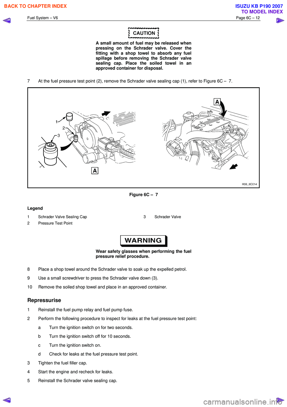
7 At the fuel pressure test point (2), remove the Schrader valve sealing cap (1), refer to Figure 6C – 7.
Figure 6C – 7
Legend
1 Schrader Valve Sealing Cap
2 Pressure Test Point 3 Schrader Valve
Wear safety glasses when performing the fuel
pressure relief procedure.
8 Place a shop towel around the Schrader valve to soak up the expelled petrol.
9 Use a small screwdriver to press the Schrader valve down (3).
10 Remove the soiled shop towel and place in an approved container.
Repressurise
1 Reinstall the fuel pump relay and fuel pump fuse.
2 Perform the following procedure to inspect for leaks at the fuel pressure test point: a Turn the ignition switch on for two seconds.
b Turn the ignition switch off for 10 seconds.
c Turn the ignition switch on.
d Check for leaks at the fuel pressure test point.
3 Tighten the fuel filler cap.
4 Start the engine and recheck for leaks.
5 Reinstall the Schrader valve sealing cap.
BACK TO CHAPTER INDEX
TO MODEL INDEX
ISUZU KB P190 2007
Page 3215 of 6020
Fuel System – V6 Page 6C – 13
4 Service Operations
4.1 Fuel Lines And Quick Connect Fittings
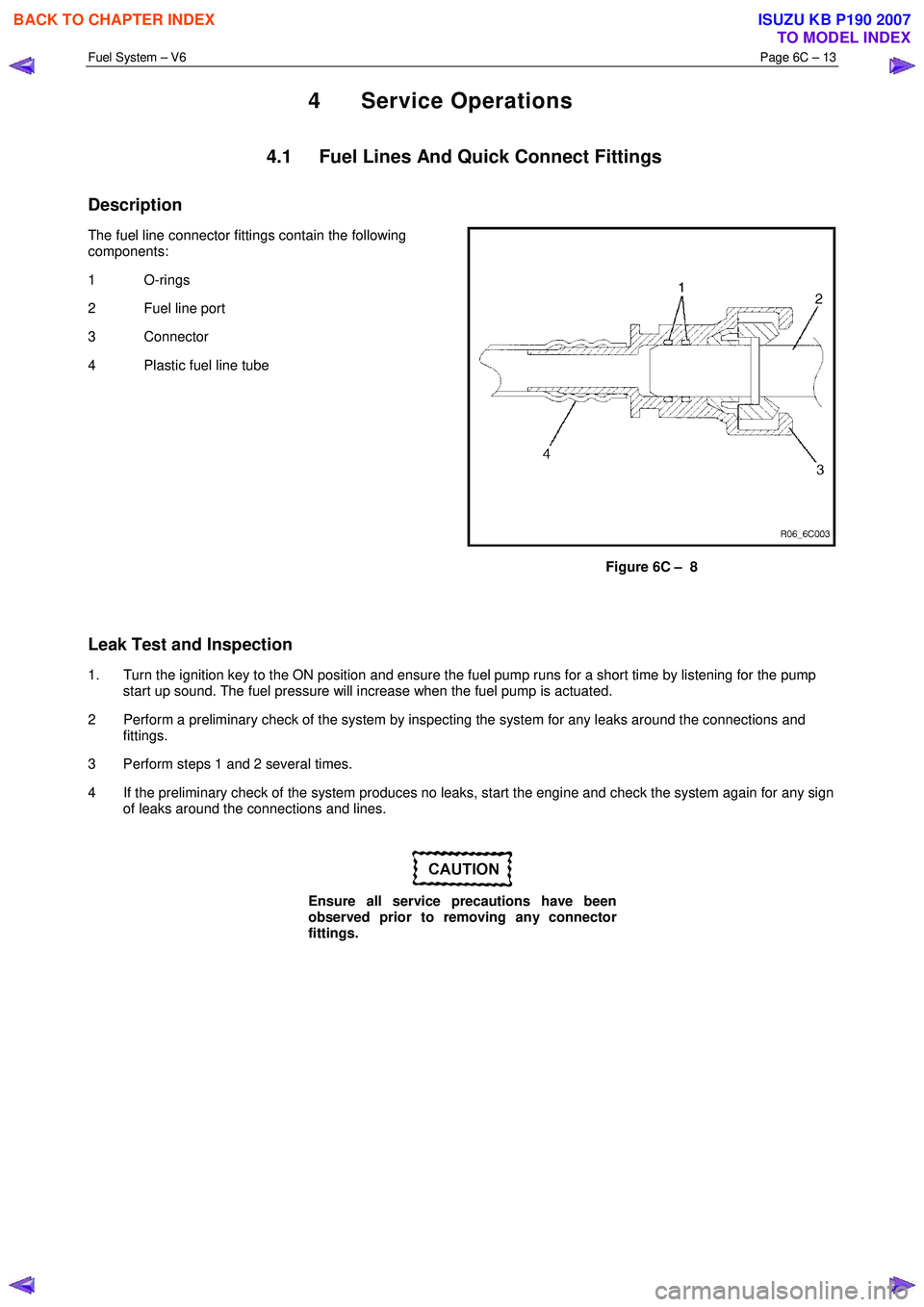
Description
The fuel line connector fittings contain the following
components:
1 O-rings
2 Fuel line port
3 Connector
4 Plastic fuel line tube
Figure 6C – 8
Leak Test and Inspection
1. Turn the ignition key to the ON position and ensure the fuel pump runs for a short time by listening for the pump start up sound. The fuel pressure will increase when the fuel pump is actuated.
2 Perform a preliminary check of the system by inspecting the system for any leaks around the connections and fittings.
3 Perform steps 1 and 2 several times.
4 If the preliminary check of the system produces no leaks, start the engine and check the system again for any sign of leaks around the connections and lines.
Ensure all service precautions have been
observed prior to removing any connector
fittings.
BACK TO CHAPTER INDEX
TO MODEL INDEX
ISUZU KB P190 2007
Page 3256 of 6020
Engine Management – V6 – General Information Page 6C1-1–14
Throttle Body Relearn Procedure
The ECM stores values that include the lowest possible TP sensor positions (zero percent), the rest positions (seven
percent), and the spring return rate. These values will only be erased or overwritten if the ECM is reprogrammed or if a
throttle body relearn procedure is performed.
NOTE
If the battery has been disconnected, the ECM
performs a throttle body relearn procedure once
the battery has been reconnected and the ignition
turned on.
The ECM performs a throttle body relearn procedure anytime the ignition is turned on and the following conditions have
been met:
• The engine has been off for greater than 29 seconds,
• The engine speed is less than 40 rpm,
• The vehicle speed is 0 km/h,
• The engine coolant temperature (ECT) is 5 – 60°C; if Tech 2 is used to perform the relearn procedure, the ECT is
5 – 100°C,
• The intake air temperature (IAT) is greater than 5 – 60°C; if Tech 2 is used to perform the relearn procedure, the
IAT is 5 – 100°C,
• The APP sensor angle is less than 15 percent, and
• Ignition voltage is greater than 10 V.
The throttle body relearn procedure is performed 29 seconds after the ignition is turned on. The ECM commands the
throttle plate from the rest position (seven percent open) to full closed (zero percent), then to around 10 percent open.
This procedure takes about six – eight seconds. If any faults occur in the TAC system, a DTC sets. At the start of this
procedure, the Tech 2 TAC Learn Counter parameter should display 0, then count up to 11 after the procedure is
completed. If the counter did not start at 0, or if the counter did not end at 11, a fault has occurred and a DTC should set.
TAC System Default Actions / Reduce Power Modes
The ECM switches to the following reduce power modes if the ECM detects a fault condition in the TAC system:
• If an APP sensor circuit fault or TP sensor circuit fault is detected, the ECM limits engine torque so the vehicle
cannot reach speeds of greater than 100 km/h. The ECM remains in this reduce power mode during the entire
ignition cycle, even if the fault is corrected.
• If there is a fault condition with the throttle actuator control circuits, a throttle actuator command vs. actual position
fault, a return spring check fault, or a TP sensor one circuit fault, the ECM limits engine speed to 2500 rpm and
three – six fuel injectors are randomly disabled. At this time the reduce power indicator is commanded on. The
ECM remains in the reduce power mode during the entire ignition cycle even if the fault is corrected.
NOTE
If a TP sensor one or throttle actuator control
circuit fault is present at the time the vehicle is at
idle, with no accelerator pedal angle, the engine
may stall.
Forced Engine Shutdown
A further safety feature which is built into the TAC system is the ECM will initiate an engine shut down if, the ECM’s
internal monitoring functions detects a serious internal fault, the fuel injectors will be turned off.
3.6 Cruise Control System
The cruise control system integrates with the engine control module (ECM) through the powertrain interface module
(PIM), to control the electronic throttle actuator and maintain the vehicle at the speed set by the driver.
BACK TO CHAPTER INDEX
TO MODEL INDEX
ISUZU KB P190 2007