brakes ISUZU KB P190 2007 Workshop Repair Manual
[x] Cancel search | Manufacturer: ISUZU, Model Year: 2007, Model line: KB P190, Model: ISUZU KB P190 2007Pages: 6020, PDF Size: 70.23 MB
Page 1 of 6020
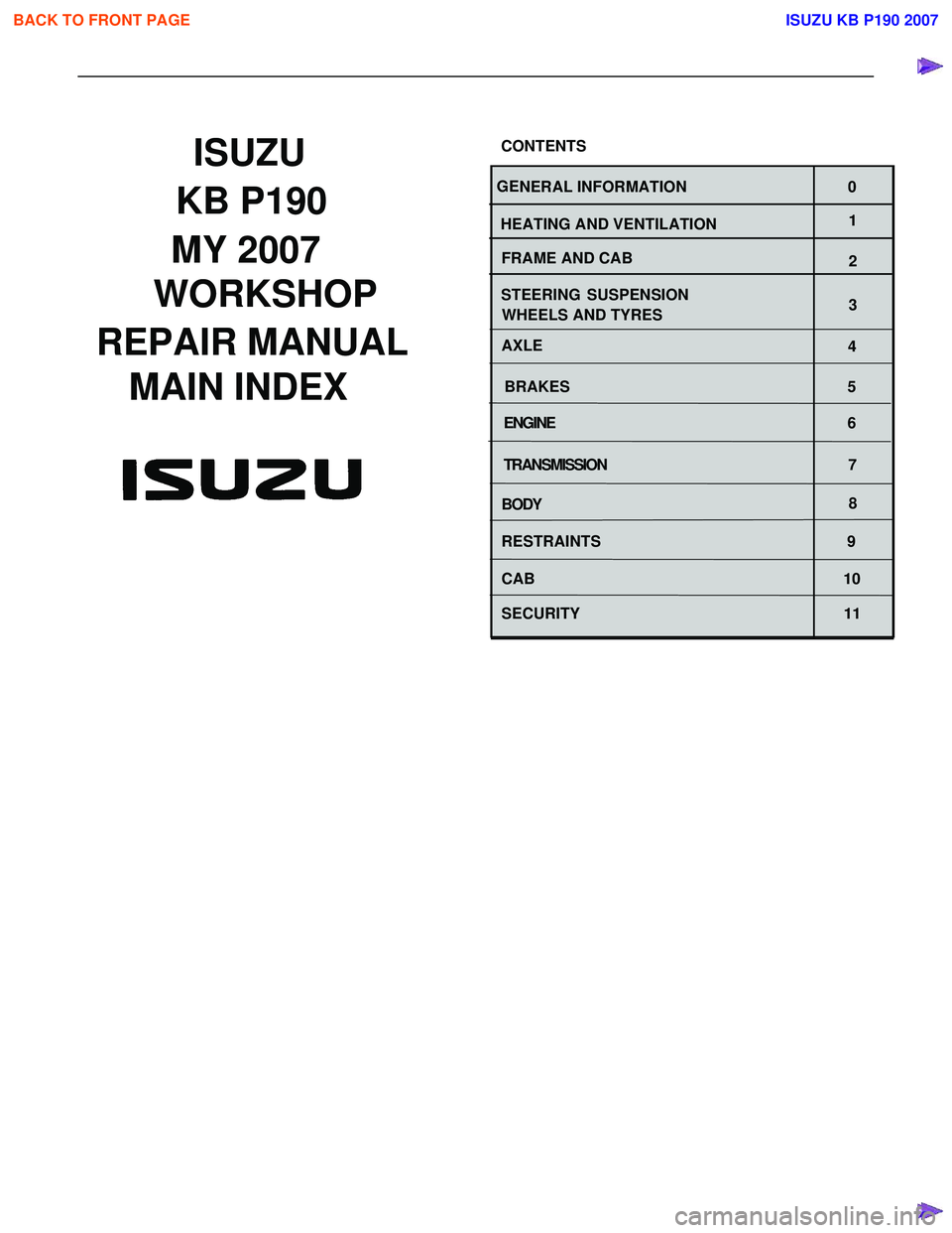
1
WORKSHOP
REPAIR MANUAL
GE NERAL INFORMATION 0
HEATING AND VENTILATION
BRAKESMAIN INDEX ISUZU
CONTENTS
WHEELS AND TYRES
4
5
BODY 8
SECURITY 11 SUSPENSION
3
STEERING
2
AXLE
FRAME AND CAB
ENGINE
6
TRANSMISSION 7
MY 2007
RESTRAINTS 9
CAB 10
BACK TO FRONT PAGE
KB P190
ISUZU KB P190 2007
Page 21 of 6020
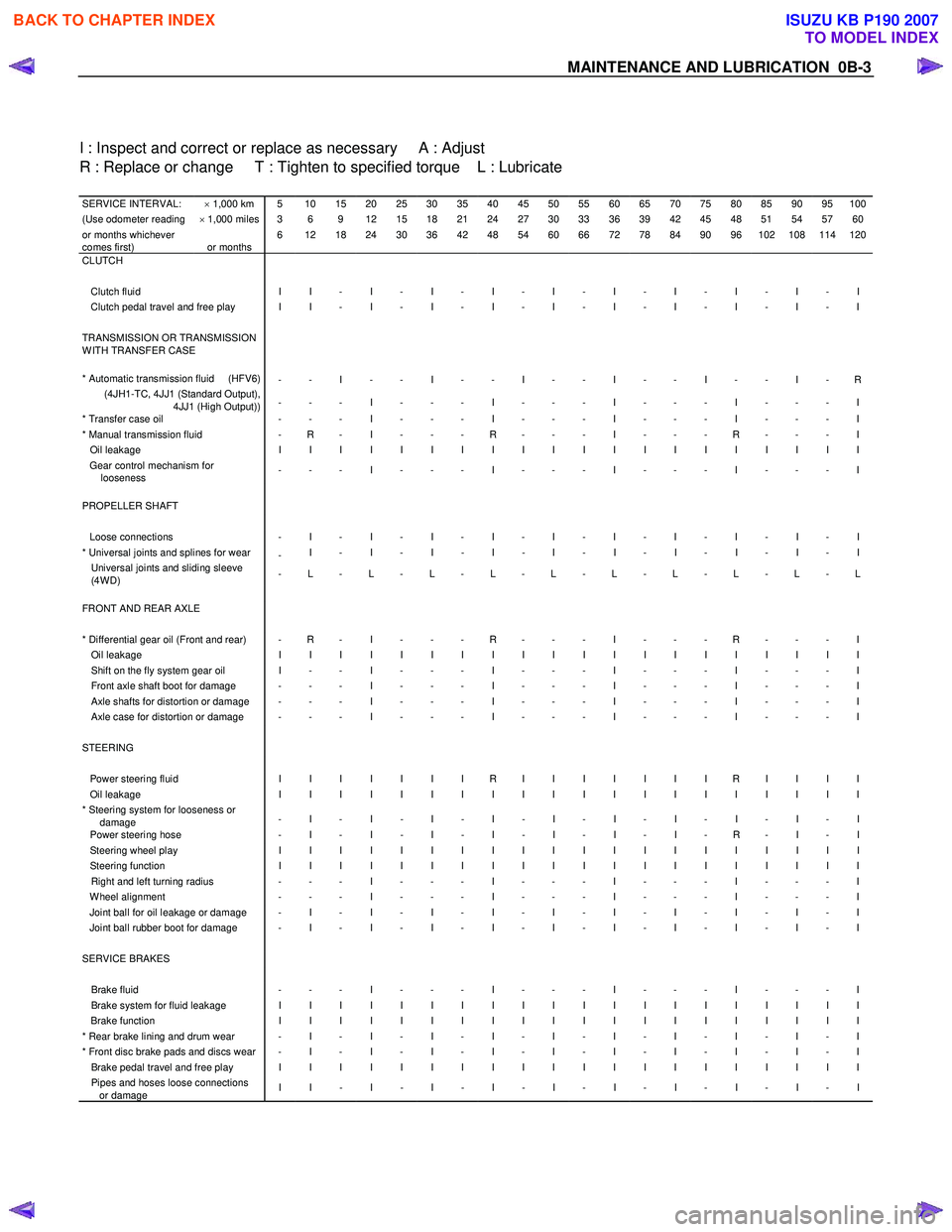
MAINTENANCE AND LUBRICATION 0B-3
I : Inspect and correct or replace as necessary A : Adjust
R : Replace or change T : Tighten to specified torque L : Lubricate
SERVICE INTERVAL: × 1,000 km 5 10 15 20 25 30 35 40 45 50 55 60 65 70 75 80 85 90 95 100(Use odometer reading × 1,000 miles 3 6 9 12 15 18 21 24 27 30 33 36 39 42 45 48 51 54 57 60or months whichever
comes first)
or months 6 12 18 24 30 36 42 48 54 60 66 72 78 84 90 96 102 108 114 120
CLUTCH
Clutch fluid I I - I - I - I - I - I - I - I - I - I Clutch pedal travel and free play I I - I - I - I - I - I - I - I - I - I TRANSMISSION OR TRANSMISSION
W ITH TRANSFER CASE
* Automatic transmission fluid (HFV6)
- - I - - I - - I - - I - - I - - I - R (4JH1-TC, 4JJ1 (Standard Output),
4JJ1 (High Output)) - - - I - - - I - - - I - - - I - - - I
* Transfer case oil
- - - I - - - I - - - I - - - I - - - I * Manual transmission fluid - R - I - - - R - - - I - - - R - - - I Oil leakage I I I I I I I I I I I I I I I I I I I I Gear control mechanism for
looseness - - - I - - - I - - - I - - - I - - - I
PROPELLER SHAFT Loose connections - I - I - I - I - I - I - I - I - I - I * Universal joints and splines for wear
- I - I - I - I - I - I - I - I - I - I Universal joints and sliding sleeve
(4W D) - L - L - L - L - L - L - L - L - L - L
FRONT AND REAR AXLE * Differential gear oil (Front and rear) - R - I - - - R - - - I - - - R - - - I Oil leakage I I I I I I I I I I I I I I I I I I I I Shift on the fly system gear oil I - - I - - - I - - - I - - - I - - - I Front axle shaft boot for damage - - - I - - - I - - - I - - - I - - - I Axle shafts for distortion or damage - - - I - - - I - - - I - - - I - - - I Axle case for distortion or damage - - - I - - - I - - - I - - - I - - - I STEERING Power steering fluid I I I I I I I R I I I I I I I R I I I I Oil leakage I I I I I I I I I I I I I I I I I I I I * Steering system for looseness or
damage - I - I - I - I - I - I - I - I - I - I
Power steering hose
- I - I - I - I - I - I - I - R - I - I Steering wheel play I I I I I I I I I I I I I I I I I I I I Steering function I I I I I I I I I I I I I I I I I I I I Right and left turning radius - - - I - - - I - - - I - - - I - - - I W heel alignment - - - I - - - I - - - I - - - I - - - I Joint ball for oil leakage or damage - I - I - I - I - I - I - I - I - I - I Joint ball rubber boot for damage - I - I - I - I - I - I - I - I - I - I SERVICE BRAKES Brake fluid - - - I - - - I - - - I - - - I - - - I Brake system for fluid leakage I I I I I I I I I I I I I I I I I I I I Brake function I I I I I I I I I I I I I I I I I I I I * Rear brake lining and drum wear - I - I - I - I - I - I - I - I - I - I * Front disc brake pads and discs wear - I - I - I - I - I - I - I - I - I - I Brake pedal travel and free play I I I I I I I I I I I I I I I I I I I I Pipes and hoses loose connections
or damage I I - I - I - I - I - I - I - I - I - I
BACK TO CHAPTER INDEX
TO MODEL INDEX
ISUZU KB P190 2007
Page 24 of 6020
0B-6 MAINTENANCE AND LUBRICATION
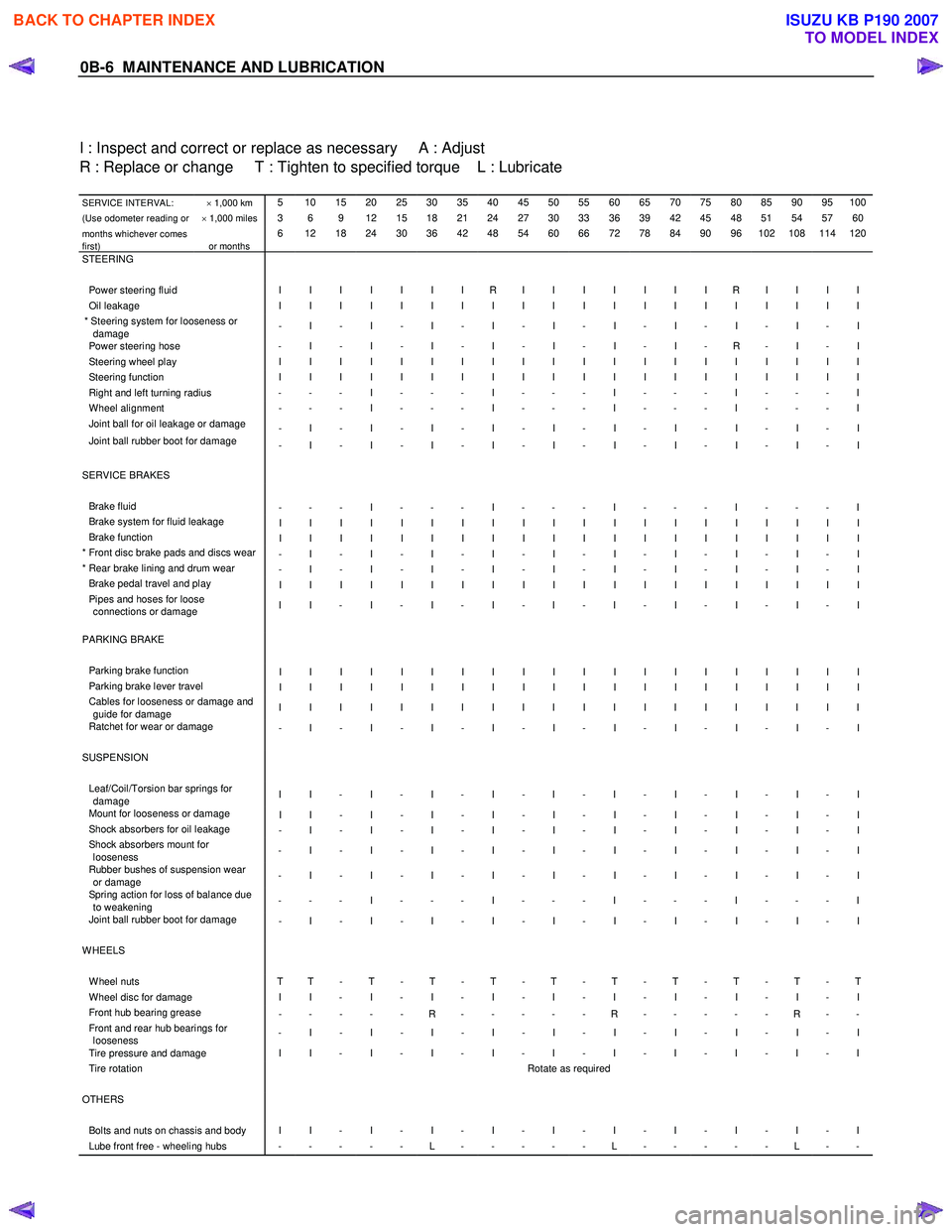
I : Inspect and correct or replace as necessary A : Adjust
R : Replace or change T : Tighten to specified torque L : Lubricate
SERVICE INTERVAL: × 1,000 km 5 10 15 20 25 30 35 40 45 50 55 60 65 70 75 80 85 90 95 100
(Use odometer reading or × 1,000 miles 3 6 9 12 15 18 21 24 27 30 33 36 39 42 45 48 51 54 57 60
months whichever comes
first)
or months 6 12 18 24 30 36 42 48 54 60 66 72 78 84 90 96 102 108 114 120
STEERING Power steering fluid I I I I I I I R I I I I I I I R I I I I Oil leakage I I I I I I I I I I I I I I I I I I I I * Steering system for looseness or
damage - I - I - I - I - I - I - I - I - I - I
Power steering hose
- I - I - I - I - I - I - I - R - I - I Steering wheel play I I I I I I I I I I I I I I I I I I I I Steering function I I I I I I I I I I I I I I I I I I I I Right and left turning radius - - - I - - - I - - - I - - - I - - - I W heel alignment - - - I - - - I - - - I - - - I - - - I Joint ball for oil leakage or damage
- I - I - I - I - I - I - I - I - I - I
Joint ball rubber boot for damage - I - I - I - I - I - I - I - I - I - I
SERVICE BRAKES Brake fluid - - - I - - - I - - - I - - - I - - - I Brake system for fluid leakage I I I I I I I I I I I I I I I I I I I I Brake function I I I I I I I I I I I I I I I I I I I I * Front disc brake pads and discs wear - I - I - I - I - I - I - I - I - I - I * Rear brake lining and drum wear - I - I - I - I - I - I - I - I - I - I Brake pedal travel and play I I I I I I I I I I I I I I I I I I I I Pipes and hoses for loose
connections or damage I I - I - I - I - I - I - I - I - I - I
PARKING BRAKE Parking brake function I I I I I I I I I I I I I I I I I I I I Parking brake lever travel I I I I I I I I I I I I I I I I I I I I Cables for looseness or damage and
guide for damage I I I I I I I I I I I I I I I I I I I I
Ratchet for wear or damage
- I - I - I - I - I - I - I - I - I - I SUSPENSION Leaf/Coil/Torsion bar springs for
damage I I - I - I - I - I - I - I - I - I - I
Mount for looseness or damage
I I - I - I - I - I - I - I - I - I - I Shock absorbers for oil leakage - I - I - I - I - I - I - I - I - I - I Shock absorbers mount for
looseness - I - I - I - I - I - I - I - I - I - I
Rubber bushes of suspension wear
or damage - I - I - I - I - I - I - I - I - I - I
Spring action for loss of balance due
to weakening - - - I - - - I - - - I - - - I - - - I
Joint ball rubber boot for damage
- I - I - I - I - I - I - I - I - I - I WHEELS W heel nuts T T - T - T - T - T - T - T - T - T - T W heel disc for damage I I - I - I - I - I - I - I - I - I - I Front hub bearing grease
- - - - - R - - - - - R - - - - - R - - Front and rear hub bearings for
looseness - I - I - I - I - I - I - I - I - I - I
Tire pressure and damage I I - I - I - I - I - I - I - I - I - I Tire rotation
Rotate as required OTHERS Bolts and nuts on chassis and body I I - I - I - I - I - I - I - I - I - I Lube front free - wheeling hubs - - - - - L - - - - - L - - - - - L - -
BACK TO CHAPTER INDEX
TO MODEL INDEX
ISUZU KB P190 2007
Page 26 of 6020
0B-8 MAINTENANCE AND LUBRICATION
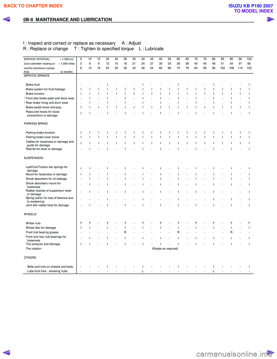
I : Inspect and correct or replace as necessary A : Adjust
R : Replace or change T : Tighten to specified torque L : Lubricate
SERVICE INTERVAL: × 1,000 km 5 10 15 20 25 30 35 40 45 50 55 60 65 70 75 80 85 90 95 100
(Use odometer reading or × 1,000 miles 3 6 9 12 15 18 21 24 27 30 33 36 39 42 45 48 51 54 57 60
months whichever comes
first)
or months 6 12 18 24 30 36 42 48 54 60 66 72 78 84 90 96 102 108 114 120
SERVICE BRAKES Brake fluid - - - I - - - I - - - I - - - I - - - I Brake system for fluid leakage I I I I I I I I I I I I I I I I I I I I Brake function I I I I I I I I I I I I I I I I I I I I * Front disc brake pads and discs wear - I - I - I - I - I - I - I - I - I - I * Rear brake lining and drum wear - I - I - I - I - I - I - I - I - I - I Brake pedal travel and play I I I I I I I I I I I I I I I I I I I I Pipes and hoses for loose
connections or damage I I - I - I - I - I - I - I - I - I - I
PARKING BRAKE Parking brake function I I I I I I I I I I I I I I I I I I I I Parking brake lever travel I I I I I I I I I I I I I I I I I I I I Cables for looseness or damage and
guide for damage I I I I I I I I I I I I I I I I I I I I
Ratchet for wear or damage - I - I - I - I - I - I - I - I - I - I
SUSPENSION Leaf/Coil/Torsion bar springs for
damage I I - I - I - I - I - I - I - I - I - I
Mount for looseness or damage I I - I - I - I - I - I - I - I - I - I Shock absorbers for oil leakage - I - I - I - I - I - I - I - I - I - I Shock absorbers mount for
looseness - I - I - I - I - I - I - I - I - I - I
Rubber bushes of suspension wear
or damage - I - I - I - I - I - I - I - I - - - I
Spring action for loss of balance due
to weakening - - - I - - - I - - - I - - - I - I - I
Joint ball rubber boot for damage - I - I - I - I - I - I - I - I - I - I
WHEELS W heel nuts T T - T - T - T - T - T - T - T - T - T W heel disc for damage I I - I - I - I - I - I - I - I - I - I Front hub bearing grease - - - - - R - - - - - R - - - - - R - - Front and rear hub bearings for
looseness - I - I - I - I - I - I - I - I - I - I
Tire pressure and damage I I - I - I - I - I - I - I - I - I - I Tire rotation
(Rotate as required) OTHERS Bolts and nuts on chassis and body - - - I - - - I - - - I - - - I - - - I Lube front free - wheeling hubs - - - - - - - L - - - - - - - L - - - -
BACK TO CHAPTER INDEX
TO MODEL INDEX
ISUZU KB P190 2007
Page 338 of 6020

3C-18 FRONT SUSPENSION
Knuckle
Knuckle and Associated Parts
450R300037
Legend
(1) Nut and Cotter Pin
(2) Back Plate
(3) Nut and Cotter Pin
(4) Nut and Cotter Pin
(5) Knuckle
(6) Bolt
Removal
1. Raise the vehicle and support the frame with
suitable safety stands.
2. Remove wheel and tire assembly. Refer to W heel in this section.
3. Remove the brake caliper. Refer to Disc Brakes in
Brake section.
4. Remove the hub assembly. Refer to Front Hub and Disk in this section.
5. Remove tie-rod end from the knuckle. Refer to Power Steering Unit in Steering section.
BACK TO CHAPTER INDEX
TO MODEL INDEX
ISUZU KB P190 2007
Page 358 of 6020

FRONT SUSPENSION 3C-37
Knuckle
Knuckle and Associated Parts
RUW 63CLF000101
Legend
(1) Torsion Bar
(2) Nut and Cotter Pin, Lower Ball Joint
(3) Back Plate
(4) Nut and Cotter Pin, Upper Ball Joint
(5) Nut and Cotter Pin, Tie-rod End
(6) Knuckle Assembly
(7) Knuckle
(8) Needle Bearing (4 ×4 Model Only)
(9) Thrust W asher (4 ×4 Model Only)
(10) Oil Seal (4 ×4 Model Only)
(11) Speed Sensor harness
Removal
1. Raise the vehicle and support the frame with suitable safety stands.
2. Remove wheel and tire assembly. Refer to W heel
in this section.
3. Remove the brake caliper. Refer to Disc Brakes in Brake section.
BACK TO CHAPTER INDEX
TO MODEL INDEX
ISUZU KB P190 2007
Page 361 of 6020

3C-40 FRONT SUSPENSION
Upper Control Arm
Upper Control Arm and Associated Parts
RTW 440LF001301
Legend
(1) Bolt and Plate
(2) Camber Shims
(3) Caster Shims
(4) Nut Assembly
(5) Upper Control Arm Assembly
(6) Fulcrum Pin
(7) Bushing
(8) Plate
(9) Upper Control Arm Nut
(10) Speed Sensor harness
(11) Nut and Cotter Pin
(12) Upper Ball Joint, Bolt and Nut
Removal
1. Raise the vehicle and support the frame with suitable safety stands.
2. Remove wheel and tire assembly. Refer to W heel
in this section.
3. Remove the brake caliper and disconnect brake pipe. Refer to Disc Brakes in Brake section.
BACK TO CHAPTER INDEX
TO MODEL INDEX
ISUZU KB P190 2007
Page 515 of 6020
FRONT WHEEL DRIVE 4C1-11
Removal
1. Jack up the vehicle and support it using jack stand.
2. Remove the tire and wheel.
3. Remove the stone guard.
4. Remove the brake caliper fixing bolt and hang the caliper. Refer to Disc Brakes in Brake section.
5. Remove the antilock brake system speed sensor.
Refer to Front W heel Speed Sensor in Brake section.
6. Remove the hub and disc assembly.
Refer to Front Hub and Disc in this section.
7. Remove the propeller shaft, refer to Front Propeller Shaft in this section.
8. Loosen the height control arm of the torsion bar, then remove the torsion bar from lower control arm.
Refer to Torsion Bar in Suspension section.
9. Remove the suspension crossmember.
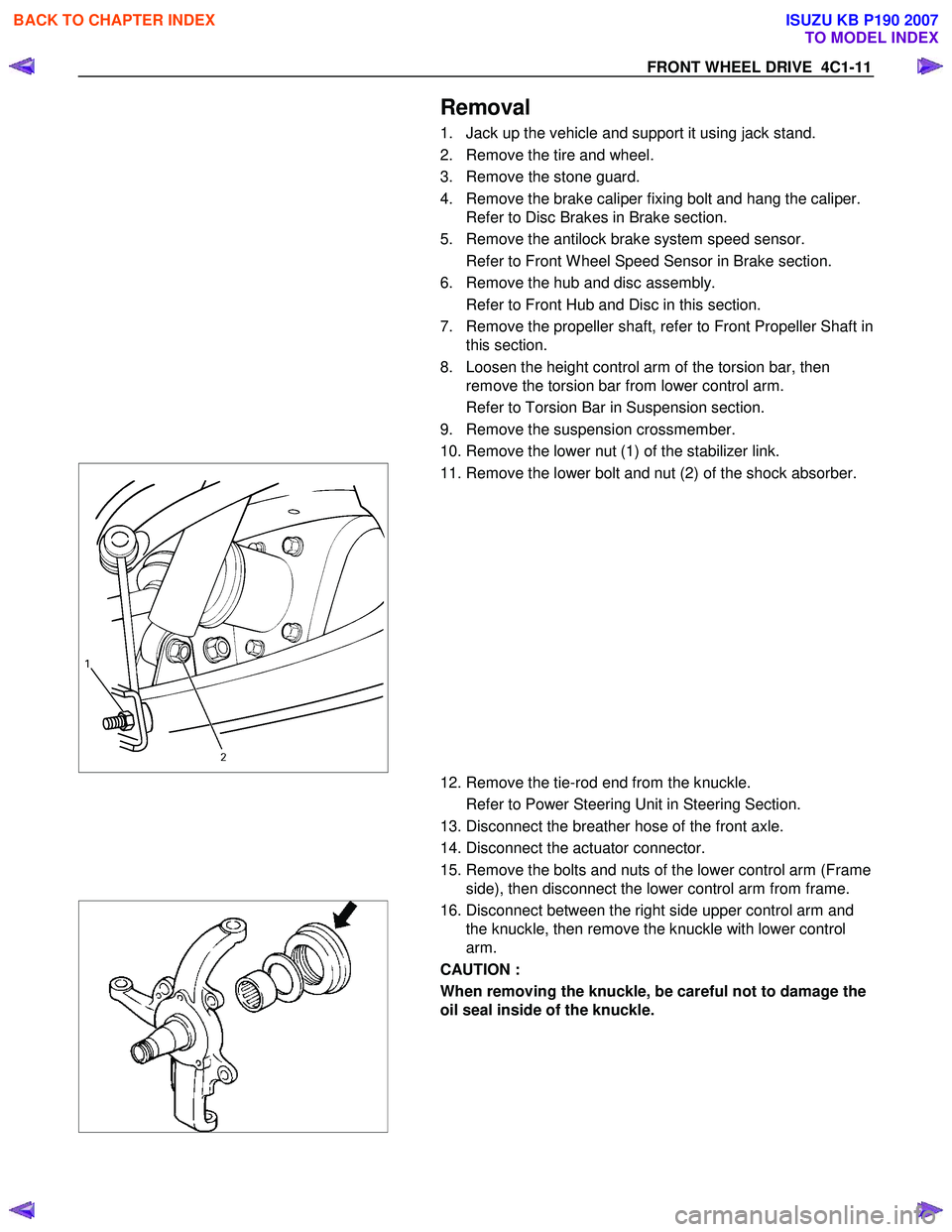
10. Remove the lower nut (1) of the stabilizer link.
11. Remove the lower bolt and nut (2) of the shock absorber.
12. Remove the tie-rod end from the knuckle.
Refer to Power Steering Unit in Steering Section.
13. Disconnect the breather hose of the front axle.
14. Disconnect the actuator connector.
15. Remove the bolts and nuts of the lower control arm (Frame side), then disconnect the lower control arm from frame.
16. Disconnect between the right side upper control arm and
the knuckle, then remove the knuckle with lower control
arm.
CAUTION :
When removing the knuckle, be careful not to damage the
oil seal inside of the knuckle.
BACK TO CHAPTER INDEX
TO MODEL INDEX
ISUZU KB P190 2007
Page 545 of 6020
FRONT WHEEL DRIVE 4C1-41
Inspection and Repair
Make necessary correction or parts replacement if wear, damage or any other abnormal conditions are found
through inspection.
For inspection and servicing of disc caliper, and relative parts, and ABS parts, refer to section 5 Brakes.
• Hub
• Hub bearing
• Bearing outer race
• Disc
• Oil seal
• Knuckle spindle
• ABS sensor rotor
• Caliper
Visual Check
Check the following parts for wear, damage or other abnormal
conditions.
BACK TO CHAPTER INDEX
TO MODEL INDEX
ISUZU KB P190 2007
Page 552 of 6020
4C1-48 FRONT WHEEL DRIVE
Inspection and Repair
Make necessary correction or parts replacement if wear, damage or any other abnormal conditions are found
through inspection.
For inspection and servicing of disc caliper, and relative parts, and ABS parts, refer to Section Brakes.
• Hub
• Hub bearing, oil seal
• Knuckle spindle
• Disc
• Caliper
• ABS sensor rotor
• Cap, Hub flange (4×4 model only),
Shim (4×4 model only), Snap ring (4×4
model only)
Visual Check
Check the following parts for wear, damage or other abnormal
conditions.
BACK TO CHAPTER INDEX
TO MODEL INDEX
ISUZU KB P190 2007