front axle ISUZU KB P190 2007 Workshop Repair Manual
[x] Cancel search | Manufacturer: ISUZU, Model Year: 2007, Model line: KB P190, Model: ISUZU KB P190 2007Pages: 6020, PDF Size: 70.23 MB
Page 1 of 6020
1
WORKSHOP
REPAIR MANUAL
GE NERAL INFORMATION 0
HEATING AND VENTILATION
BRAKESMAIN INDEX ISUZU
CONTENTS
WHEELS AND TYRES
4
5
BODY 8
SECURITY 11 SUSPENSION
3
STEERING
2
AXLE
FRAME AND CAB
ENGINE
6
TRANSMISSION 7
MY 2007
RESTRAINTS 9
CAB 10
BACK TO FRONT PAGE
KB P190
ISUZU KB P190 2007
Page 4 of 6020
0A-2 GENERAL INFORMATION
GENERAL REPAIR INSTRUCTIONS
1. Park the vehicle on level ground and chock the front or rear wheels before lifting the vehicle.
2. Raise the vehicle with a jack set against the axle or the frame.
3. Support the vehicle on chassis stands.
4. Use covers on the vehicle body, seats, and floor to prevent damage and/or contamination.
5. Disconnect the grounding cable from the battery before performing service operations.
This will prevent cable damage or burning due to short circuiting.
6. Handle brake fluid and antifreeze solution with great care.
Spilling these liquids on painted surfaces will damage the paint.
7. The use of the proper tool(s) and special tool(s) where specified is essential to efficient, reliable, and safe
service operations.
8. Always use genuine ISUZU replacement parts.
9. Discard used cotter pins, gaskets, O-rings, oil seals, lock washers, and self-locking nuts at disassembly.
Normal function of these parts cannot be guaranteed if they are reused.
10. Prepare new cotter pins, gaskets, O-rings, oil seals, lock washers, and self-locking nuts for installation.
11. Keep the disassembled parts neatly in groups. This will facilitate smooth and correct reassembly.
12. Keep fixing nuts and bolts separate. Fixing nuts and bolts vary in hardness and design according to installation position.
13. Clean all parts before inspection or reassembly.
14. Clean the oil ports and other openings with compressed air to make certain that they are free from dirt and obstructions.
15. Lubricate the rotating and sliding faces of all moving parts with oil or grease before installation.
16. Use the recommended liquid gasket to prevent leakage.
17. Carefully observe all nut and bolt torque specifications.
18. W hen removing or replacing parts that require refrigerant to the discharged from the air conditioning system, be sure to use the Vehicle Refrigerant Recovery and Recycling Equipment (VRRRE) to recover and recycle R134a,
to promote the aim of the protection of the ozone layer covering the earth.
19. Check and recheck your work. No service operation is complete until you have done this.
BACK TO CHAPTER INDEX
TO MODEL INDEX
ISUZU KB P190 2007
Page 10 of 6020
0A-8 GENERAL INFORMATION
RUW 50ASH000101
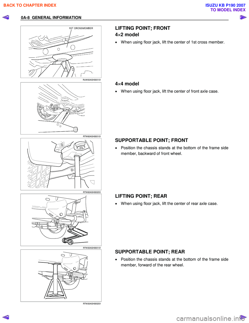
LIFTING POINT; FRONT
4 ×
××
×
2 model
• W hen using floor jack, lift the center of 1st cross member.
RTW 60ASH000101
4 ×
××
×
4 model
• W hen using floor jack, lift the center of front axle case.
RTW 60ASH000201
SUPPORTABLE POINT; FRONT
• Position the chassis stands at the bottom of the frame side
member, backward of front wheel.
RTW 30ASH000101
LIFTING POINT; REAR
• W hen using floor jack, lift the center of rear axle case.
RTW 30ASH000201
SUPPORTABLE POINT; REAR
• Position the chassis stands at the bottom of the frame side
member, forward of the rear wheel.
BACK TO CHAPTER INDEX
TO MODEL INDEX
ISUZU KB P190 2007
Page 21 of 6020
MAINTENANCE AND LUBRICATION 0B-3
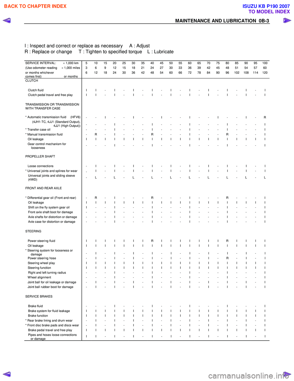
I : Inspect and correct or replace as necessary A : Adjust
R : Replace or change T : Tighten to specified torque L : Lubricate
SERVICE INTERVAL: × 1,000 km 5 10 15 20 25 30 35 40 45 50 55 60 65 70 75 80 85 90 95 100(Use odometer reading × 1,000 miles 3 6 9 12 15 18 21 24 27 30 33 36 39 42 45 48 51 54 57 60or months whichever
comes first)
or months 6 12 18 24 30 36 42 48 54 60 66 72 78 84 90 96 102 108 114 120
CLUTCH
Clutch fluid I I - I - I - I - I - I - I - I - I - I Clutch pedal travel and free play I I - I - I - I - I - I - I - I - I - I TRANSMISSION OR TRANSMISSION
W ITH TRANSFER CASE
* Automatic transmission fluid (HFV6)
- - I - - I - - I - - I - - I - - I - R (4JH1-TC, 4JJ1 (Standard Output),
4JJ1 (High Output)) - - - I - - - I - - - I - - - I - - - I
* Transfer case oil
- - - I - - - I - - - I - - - I - - - I * Manual transmission fluid - R - I - - - R - - - I - - - R - - - I Oil leakage I I I I I I I I I I I I I I I I I I I I Gear control mechanism for
looseness - - - I - - - I - - - I - - - I - - - I
PROPELLER SHAFT Loose connections - I - I - I - I - I - I - I - I - I - I * Universal joints and splines for wear
- I - I - I - I - I - I - I - I - I - I Universal joints and sliding sleeve
(4W D) - L - L - L - L - L - L - L - L - L - L
FRONT AND REAR AXLE * Differential gear oil (Front and rear) - R - I - - - R - - - I - - - R - - - I Oil leakage I I I I I I I I I I I I I I I I I I I I Shift on the fly system gear oil I - - I - - - I - - - I - - - I - - - I Front axle shaft boot for damage - - - I - - - I - - - I - - - I - - - I Axle shafts for distortion or damage - - - I - - - I - - - I - - - I - - - I Axle case for distortion or damage - - - I - - - I - - - I - - - I - - - I STEERING Power steering fluid I I I I I I I R I I I I I I I R I I I I Oil leakage I I I I I I I I I I I I I I I I I I I I * Steering system for looseness or
damage - I - I - I - I - I - I - I - I - I - I
Power steering hose
- I - I - I - I - I - I - I - R - I - I Steering wheel play I I I I I I I I I I I I I I I I I I I I Steering function I I I I I I I I I I I I I I I I I I I I Right and left turning radius - - - I - - - I - - - I - - - I - - - I W heel alignment - - - I - - - I - - - I - - - I - - - I Joint ball for oil leakage or damage - I - I - I - I - I - I - I - I - I - I Joint ball rubber boot for damage - I - I - I - I - I - I - I - I - I - I SERVICE BRAKES Brake fluid - - - I - - - I - - - I - - - I - - - I Brake system for fluid leakage I I I I I I I I I I I I I I I I I I I I Brake function I I I I I I I I I I I I I I I I I I I I * Rear brake lining and drum wear - I - I - I - I - I - I - I - I - I - I * Front disc brake pads and discs wear - I - I - I - I - I - I - I - I - I - I Brake pedal travel and free play I I I I I I I I I I I I I I I I I I I I Pipes and hoses loose connections
or damage I I - I - I - I - I - I - I - I - I - I
BACK TO CHAPTER INDEX
TO MODEL INDEX
ISUZU KB P190 2007
Page 23 of 6020
MAINTENANCE AND LUBRICATION 0B-5
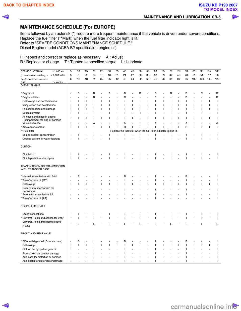
MAINTENANCE SCHEDULE (For EUROPE)
Items followed by an asterisk (*) require more frequent maintenance if the vehicle is driven under severe conditions.
Replace the fuel filter (**Mark) when the fuel filter indicator light is lit.
Refer to "SEVERE CONDITIONS MAINTENANCE SCHEDULE."
Diesel Engine model (ACEA B2 specification engine oil)
I : Inspect and correct or replace as necessary A : Adjust
R : Replace or change T : Tighten to specified torque L : Lubricate
SERVICE INTERVAL: × 1,000 km 5 10 15 20 25 30 35 40 45 50 55 60 65 70 75 80 85 90 95 100
(Use odometer reading or × 1,000 miles 3 6 9 12 15 18 21 24 27 30 33 36 39 42 45 48 51 54 57 60
months whichever comes
first)
or months 6 12 18 24 30 36 42 48 54 60 66 72 78 84 90 96 102 108 114 120
DIESEL ENGINE * Engine oil - R - R - R - R - R - R - R - R - R - R* Engine oil filter - - - R - - - R - - - R - - - R - - - ROil leakage and contamination I I I I I I I I I I I I I I I I I I I I Idling speed and acceleration I I I I I I I I I I I I I I I I I I I I Fan belt tension and damage I I I I I I I I I I I I I I I I I I I I Exhaust system I I - I - I - I - I - I - I - I - I - I All hoses and pipes in engine
compartment for clog of damage - I I I I I I I I I I I I I I I I I I I
Valve clearance
- - - A - - - A - - - A - - - A - - - A * Air cleaner element I I I I I I I R I I I I I I I R I I I I ** Fuel filter Replace the fuel filter when the fuel filter indicator light is lit. Engine coolant concentration - I - I - I - I - I - I - I - I - I - I Cooling system for water leakage - I - I - I - I - I - I - I - I - I - I CLUTCH Clutch fluid I I - I - I - I - I - I - I - I - I - I Clutch pedal travel and play I I - I - I - I - I - I - I - I - I - I TRANSMISSION OR TRANSMISSION
W ITH TRANSFER CASE
* Manual transmission with fluid - R - I - - - R - - - I - - - R - - - I * Transfer case oil (MT) - - - I - - - I - - - I - - - I - - - I Oil leakage I I I I I I I I I I I I I I I I I I I I Gear control mechanism for
looseness - - - I - - - I - - - I - - - I - - - I
* Automatic transmission fluid - - - I - - - I - - - I - - - I - - - I * Transfer case oil (AT)
- - - I - - - - - - - I - - - - - - - I PROPELLER SHAFT Loose connections - I - I - I - I - I - I - I - I - I - I * Universal joints and splines for wear - I - I - I - I - I - I - I - I - I - I Universal joints and sliding sleeve (4W D) - L - L - L - L - L - L - L - L - L - L
FRONT AND REAR AXLE * Differential gear oil (Front and rear) - R - I - - - R - - - I - - - R - - - I Oil leakage I I I I I I I I I I I I I I I I I I I I Shift on the fly system gear oil I - - I - - - I - - - I - - - I - - - I
Front axle shaft boot for damage - - - I - - - I - - - I - - - I - - - I Axle case for distortion or damage - - - I - - - I - - - I - - - I - - - I Axle shafts for distortion or damage - - - I - - - I - - - I - - - I - - - I
BACK TO CHAPTER INDEX
TO MODEL INDEX
ISUZU KB P190 2007
Page 25 of 6020
MAINTENANCE AND LUBRICATION 0B-7
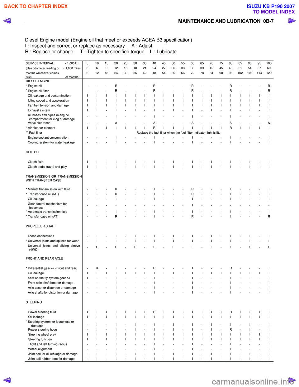
Diesel Engine model (Engine oil that meet or exceeds ACEA B3 specification)
I : Inspect and correct or replace as necessary A : Adjust
R : Replace or change T : Tighten to specified torque L : Lubricate
SERVICE INTERVAL: × 1,000 km 5 10 15 20 25 30 35 40 45 50 55 60 65 70 75 80 85 90 95 100
(Use odometer reading or × 1,000 miles 3 6 9 12 15 18 21 24 27 30 33 36 39 42 45 48 51 54 57 60
months whichever comes
first)
or months 6 12 18 24 30 36 42 48 54 60 66 72 78 84 90 96 102 108 114 120
DIESEL ENGINE * Engine oil - - - R - - - R - - - R - - - R - - - R*
Engine oil filter
- - - R - - - R - - - R - - - R - - - R
Oil leakage and contamination I I I I I I I I I I I I I I I I I I I I Idling speed and acceleration I I I I I I I I I I I I I I I I I I I I Fan belt tension and damage I I I I I I I I I I I I I I I I I I I I Exhaust system I I - I - I - I - I - I - I - I - I - I All hoses and pipes in engine
compartment for clog of damage - - - I - - - I - - - I - - - I - - - I
Valve clearance
- - - A - - - A - - - A - - - A - - - A * Air cleaner element I I I I I I I R I I I I I I I R I I I I ** Fuel filter Replace the fuel filter when the fuel filter indicator light is lit. Engine coolant concentration - - - I - - - I - - - I - - - I - - - I Cooling system for water leakage - - - I - - - I - - - I - - - I - - - I CLUTCH Clutch fluid I I - I - I - I - I - I - I - I - I - I Clutch pedal travel and play I I - I - I - I - I - I - I - I - I - I TRANSMISSION OR TRANSMISSION
W ITH TRANSFER CASE
* Manual transmission with fluid - - - R - - - I - - - R - - - I - - - I * Transfer case oil (MT) - - - R - - - I - - - R - - - I - - - I Oil leakage - - - I - - - I - - - I - - - I - - - I Gear control mechanism for
looseness - - - - - - - - - - - I - - - - - - - -
* Automatic transmission fluid - - - I - - - I - - - I - - - I - - - I * Transfer case oil (AT)
- - - R - - - I - - - R - - - I - - - R PROPELLER SHAFT Loose connections - I - I - I - I - I - I - I - I - I - I * Universal joints and splines for wear - I - I - I - I - I - I - I - I - I - I Universal joints and sliding sleeve
(4W D) - L - L - L - L - L - L - L - L - L - L
FRONT AND REAR AXLE
* Differential gear oil (Front and rear) - R - I - - - R - - - I - - - R - - - I Oil leakage I I I I I I I I I I I I I I I I I I I I Shift on the fly system gear oil I - - I - - - I - - - I - - - I - - - I Front axle shaft boot for damage - - - I - - - I - - - I - - - I - - - I Axle case for distortion or damage - - - I - - - I - - - I - - - I - - - I Axle shafts for distortion or damage - - - I - - - I - - - I - - - I - - - I STEERING Power steering fluid I I I I I I I R I I I I I I I R I I I I Oil leakage I I I I I I I I I I I I I I I I I I I I * Steering system for looseness or
damage - I - I - I - I - I - I - I - I - I - I
Power steering hose
- I - I - I - I - I - I - I - R - I - I Steering wheel play I I I I I I I I I I I I I I I I I I I I Steering function I I I I I I I I I I I I I I I I I I I I Right and left turning radius - - - I - - - I - - - I - - - I - - - I W heel alignment - - - I - - - I - - - I - - - I - - - I Joint ball for oil leakage or damage - I - I - I - I - I - I - I - I - I - I Joint ball rubber boot for damage - I - I - I - I - I - I - I - I - I - I
BACK TO CHAPTER INDEX
TO MODEL INDEX
ISUZU KB P190 2007
Page 34 of 6020
0B-16 MAINTENANCE AND LUBRICATION
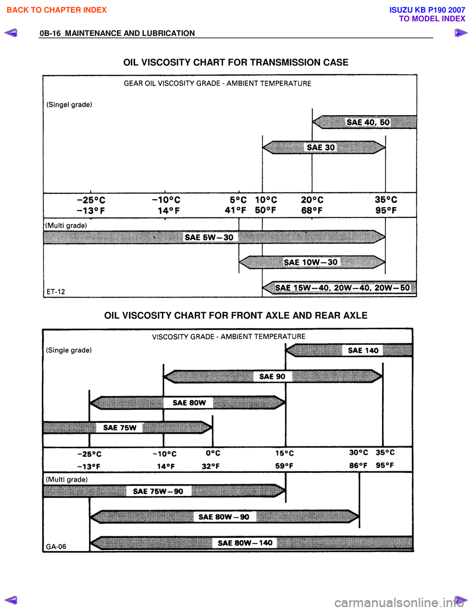
OIL VISCOSITY CHART FOR TRANSMISSION CASE
OIL VISCOSITY CHART FOR FRONT AXLE AND REAR AXLE
BACK TO CHAPTER INDEX
TO MODEL INDEX
ISUZU KB P190 2007
Page 250 of 6020
3A-2 FRONT ALIGNMENT
Front End Alignment Inspection and
Adjustment
General Description
“Front End Alignment” refers to the angular relationship
between the front wheels, the front suspension attaching parts
and the ground.
Proper front end alignment must be maintained in order to
insure efficient steering, good directional stability and to
prevent abnormal tire wear.
The most important factors of front end alignment are wheel
toe-in, wheel camber and axle caster.
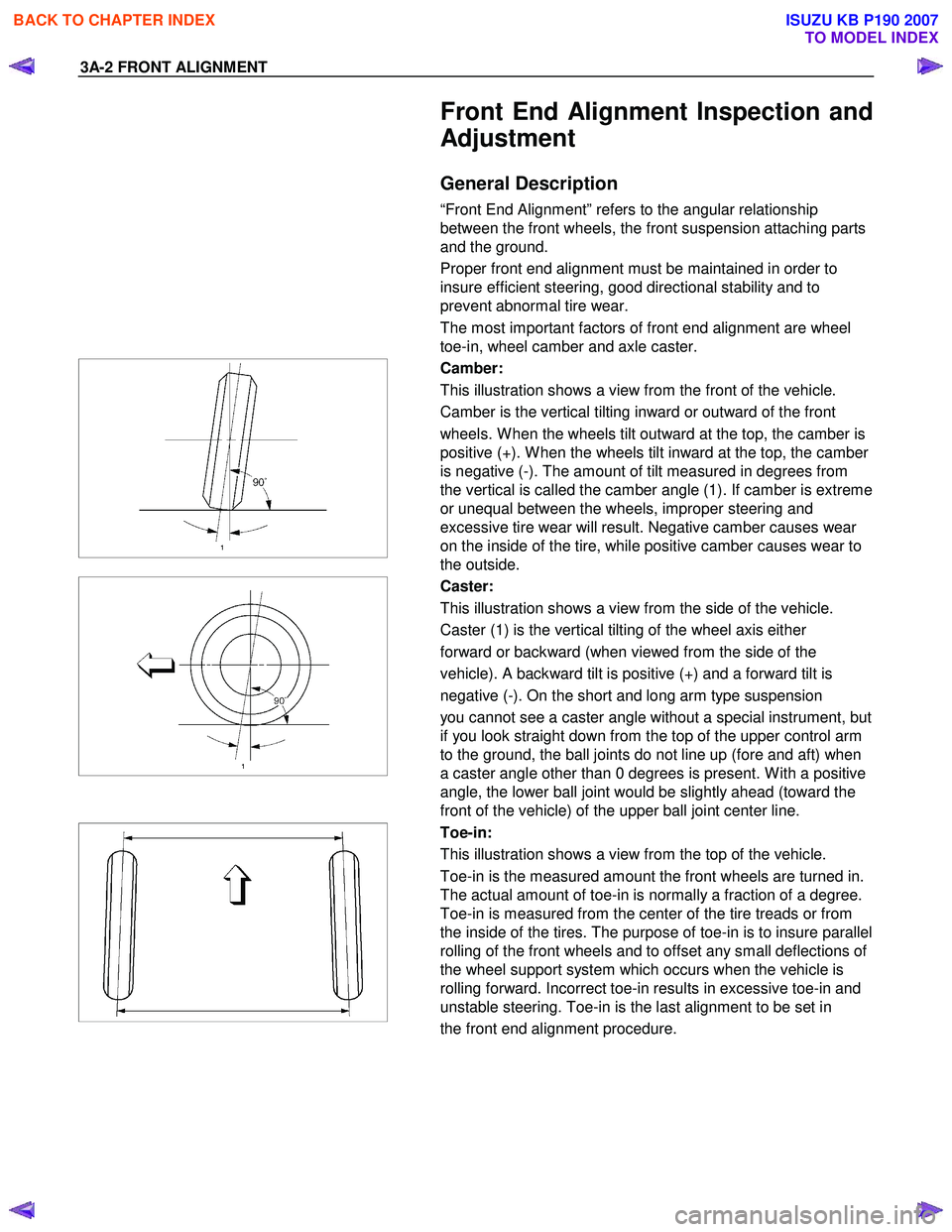
Camber:
This illustration shows a view from the front of the vehicle.
Camber is the vertical tilting inward or outward of the front
wheels. W hen the wheels tilt outward at the top, the camber is
positive (+). W hen the wheels tilt inward at the top, the camber
is negative (-). The amount of tilt measured in degrees from
the vertical is called the camber angle (1). If camber is extreme
or unequal between the wheels, improper steering and
excessive tire wear will result. Negative camber causes wear
on the inside of the tire, while positive camber causes wear to
the outside.
Caster:
This illustration shows a view from the side of the vehicle.
Caster (1) is the vertical tilting of the wheel axis either
forward or backward (when viewed from the side of the
vehicle). A backward tilt is positive (+) and a forward tilt is
negative (-). On the short and long arm type suspension
you cannot see a caster angle without a special instrument, but
if you look straight down from the top of the upper control arm
to the ground, the ball joints do not line up (fore and aft) when
a caster angle other than 0 degrees is present. W ith a positive
angle, the lower ball joint would be slightly ahead (toward the
front of the vehicle) of the upper ball joint center line.
Toe-in:
This illustration shows a view from the top of the vehicle.
Toe-in is the measured amount the front wheels are turned in.
The actual amount of toe-in is normally a fraction of a degree.
Toe-in is measured from the center of the tire treads or from
the inside of the tires. The purpose of toe-in is to insure parallel
rolling of the front wheels and to offset any small deflections of
the wheel support system which occurs when the vehicle is
rolling forward. Incorrect toe-in results in excessive toe-in and
unstable steering. Toe-in is the last alignment to be set in
the front end alignment procedure.
BACK TO CHAPTER INDEX
TO MODEL INDEX
ISUZU KB P190 2007
Page 366 of 6020
FRONT SUSPENSION 3C-45
Removal
1. Raise the vehicle and support the frame with
suitable safety stands.
2. Remove wheel and tire assembly. Refer to W heel in this section.
3. Remove the tie-rod end from the knuckle. Refer to Power Steering Unit in Steering section.
4. Remove the retaining ring from the front axle driving shaft to release the shaft from hub. Refer to
Front Hub and Disc in Driveline/Axle section.
5. Support lower control arm with a jack.
6. Remove cam plate and nut.
7. Remove rear nut.
8. Remove torsion bar; refer to Torsion Bar in this section.
9. Remove torsion bar arm bracket.
10. Disconnect the stabilizer link at the lower control arm.
11. Remove the shock absorber lower end from the lower control arm.
12. Remove the lower ball joint from the lower control arm.
13. Remove cam bolt.
14. Remove rear bolt.
15. Remove lower control arm.
16. Remove torsion bar arm bolt.
17. Remove lower ball joint bolt.
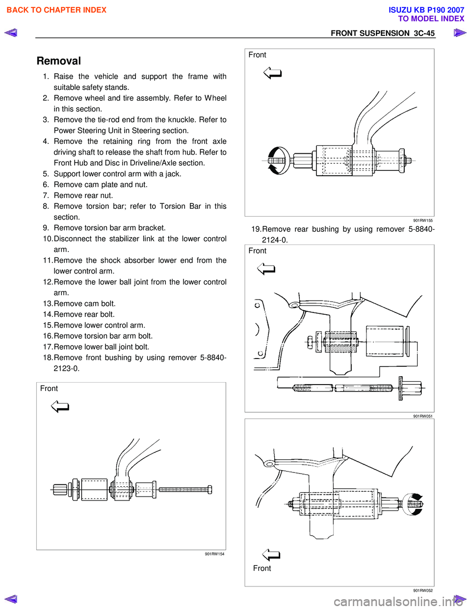
18. Remove front bushing by using remover 5-8840- 2123-0.
Front
901RW 154
Front
901RW 155
19. Remove rear bushing by using remover 5-8840-
2124-0.
Front
901RW 051
Front
901RW 052
BACK TO CHAPTER INDEX
TO MODEL INDEX
ISUZU KB P190 2007
Page 371 of 6020

3C-50 FRONT SUSPENSION
Lower Ball Joint
Lower Ball Joint and Associated Parts
RTW 340LF001601
Legend
(1) Lower Ball Joint Bolt
(2) Lower Ball Joint
(3) Lower Ball Joint Nut
(4) Nut and Cotter Pin
Removal
1. Raise the vehicle and support the frame with suitable safety stands.
2. Remove wheel and tire assembly. Refer to W heel in this section.
3. Remove the tie-rod end from the knuckle. Refer to Power Steering Unit in Steering section.
4. Remove the retaining ring from the front axle
driving shaft to release the shaft from hub. Refer to
Front Hub and Disc in Driveline/Axle section.
5. Support lower control arm with a jack.
6. Remove lower ball joint nut and cotter pin, then use remover 5-8840-2005-0 to remove the lowe
r
ball joint from the knuckle.
BACK TO CHAPTER INDEX
TO MODEL INDEX
ISUZU KB P190 2007