glove box ISUZU KB P190 2007 Workshop Repair Manual
[x] Cancel search | Manufacturer: ISUZU, Model Year: 2007, Model line: KB P190, Model: ISUZU KB P190 2007Pages: 6020, PDF Size: 70.23 MB
Page 99 of 6020
HEATER AND AIR CONDITIONING 1-65
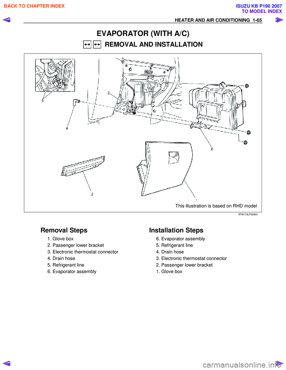
EVAPORATOR (WITH A/C)
REMOVAL AND INSTALLATION
This illustration is based on RHD model
RTW 710LF003001
Removal Steps
1. Glove box
2. Passenger lower bracket
3. Electronic thermostat connector
4. Drain hose
5. Refrigerant line
6. Evaporator assembly
Installation Steps
6. Evaporator assembly
5. Refrigerant line
4. Drain hose
3. Electronic thermostat connector
2. Passenger lower bracket
1. Glove box
BACK TO CHAPTER INDEX
TO MODEL INDEX
ISUZU KB P190 2007
Page 102 of 6020
1-68 HEATER AND AIR CONDITIONING
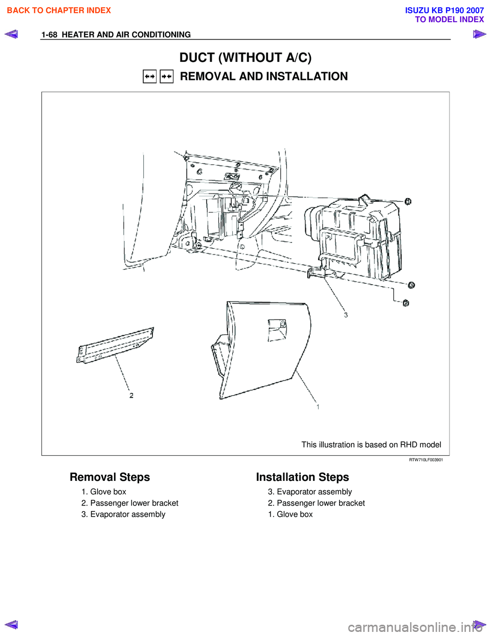
DUCT (WITHOUT A/C)
REMOVAL AND INSTALLATION
This illustration is based on RHD model
RTW 710LF003901
Removal Steps
1. Glove box
2. Passenger lower bracket
3. Evaporator assembly
Installation Steps
3. Evaporator assembly
2. Passenger lower bracket
1. Glove box
BACK TO CHAPTER INDEX
TO MODEL INDEX
ISUZU KB P190 2007
Page 109 of 6020
HEATER AND AIR CONDITIONING 1-75
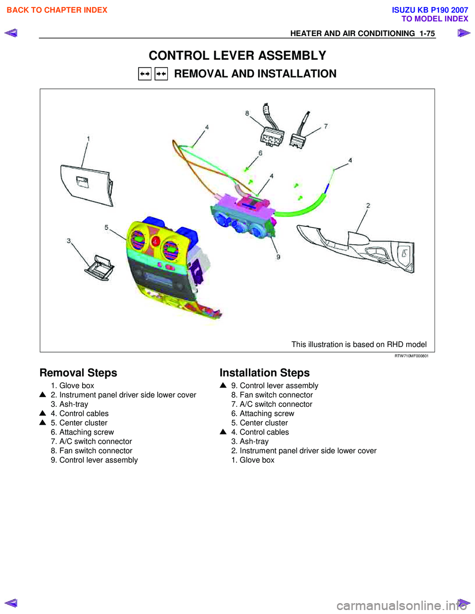
CONTROL LEVER ASSEMBLY
REMOVAL AND INSTALLATION
This illustration is based on RHD model
RTW 710MF000801
Removal Steps
1. Glove box
2. Instrument panel driver side lower cover
3. Ash-tray
4. Control cables
5. Center cluster
6. Attaching screw
7. A/C switch connector
8. Fan switch connector
9. Control lever assembly
Installation Steps
9. Control lever assembly
8. Fan switch connector
7. A/C switch connector
6. Attaching screw
5. Center cluster
4. Control cables
3. Ash-tray
2. Instrument panel driver side lower cover
1. Glove box
BACK TO CHAPTER INDEX
TO MODEL INDEX
ISUZU KB P190 2007
Page 772 of 6020
5D-2 PARKING BRAKE SYSTEM
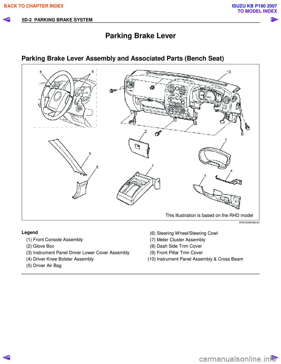
Parking Brake Lever
Parking Brake Lever Assembly and Associated Parts (Bench Seat)
This illustration is based on the RHD model
RTW 75DMF000101
Legend
(1) Front Console Assembly
(2) Glove Box
(3) Instrument Panel Driver Lower Cover Assembly
(4) Driver Knee Bolster Assembly
(5) Driver Air Bag
(6) Steering W heel/Steering Cowl
(7) Meter Cluster Assembly
(8) Dash Side Trim Cover
(9) Front Pillar Trim Cover
(10) Instrument Panel Assembly & Cross Beam
BACK TO CHAPTER INDEX
TO MODEL INDEX
ISUZU KB P190 2007
Page 1283 of 6020
Engine Control System (4JH1) 6E-249
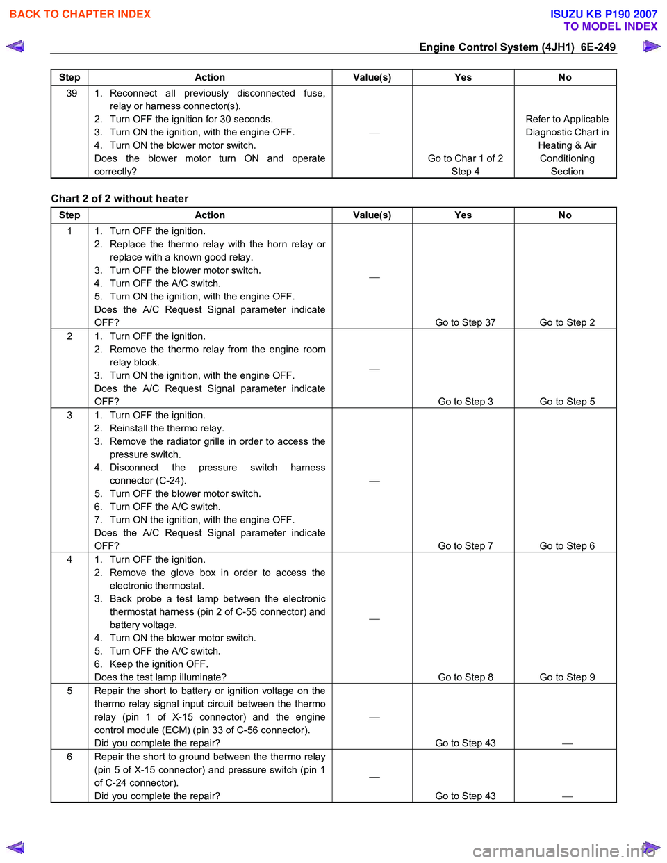
Step Action Value(s) Yes No
39 1. Reconnect all previously disconnected fuse,
relay or harness connector(s).
2. Turn OFF the ignition for 30 seconds.
3. Turn ON the ignition, with the engine OFF.
4. Turn ON the blower motor switch.
Does the blower motor turn ON and operate
correctly?
Go to Char 1 of 2 Step 4 Refer to Applicable
Diagnostic Chart in Heating & Air Conditioning Section
Chart 2 of 2 without heater
Step Action Value(s) Yes No
1 1. Turn OFF the ignition.
2. Replace the thermo relay with the horn relay or replace with a known good relay.
3. Turn OFF the blower motor switch.
4. Turn OFF the A/C switch.
5. Turn ON the ignition, with the engine OFF.
Does the A/C Request Signal parameter indicate
OFF?
Go to Step 37 Go to Step 2
2 1. Turn OFF the ignition. 2. Remove the thermo relay from the engine room relay block.
3. Turn ON the ignition, with the engine OFF.
Does the A/C Request Signal parameter indicate
OFF?
Go to Step 3 Go to Step 5
3 1. Turn OFF the ignition. 2. Reinstall the thermo relay.
3. Remove the radiator grille in order to access the pressure switch.
4. Disconnect the pressure switch harness connector (C-24).
5. Turn OFF the blower motor switch.
6. Turn OFF the A/C switch.
7. Turn ON the ignition, with the engine OFF.
Does the A/C Request Signal parameter indicate
OFF?
Go to Step 7 Go to Step 6
4 1. Turn OFF the ignition. 2. Remove the glove box in order to access the electronic thermostat.
3. Back probe a test lamp between the electronic thermostat harness (pin 2 of C-55 connector) and
battery voltage.
4. Turn ON the blower motor switch.
5. Turn OFF the A/C switch.
6. Keep the ignition OFF.
Does the test lamp illuminate?
Go to Step 8 Go to Step 9
5 Repair the short to battery or ignition voltage on the thermo relay signal input circuit between the thermo
relay (pin 1 of X-15 connector) and the engine
control module (ECM) (pin 33 of C-56 connector).
Did you complete the repair?
Go to Step 43
6 Repair the short to ground between the thermo relay
(pin 5 of X-15 connector) and pressure switch (pin 1
of C-24 connector).
Did you complete the repair?
Go to Step 43
BACK TO CHAPTER INDEX
TO MODEL INDEX
ISUZU KB P190 2007
Page 1363 of 6020
ENGINE MECHANICAL (4JK1/4JJ1) 6A-3
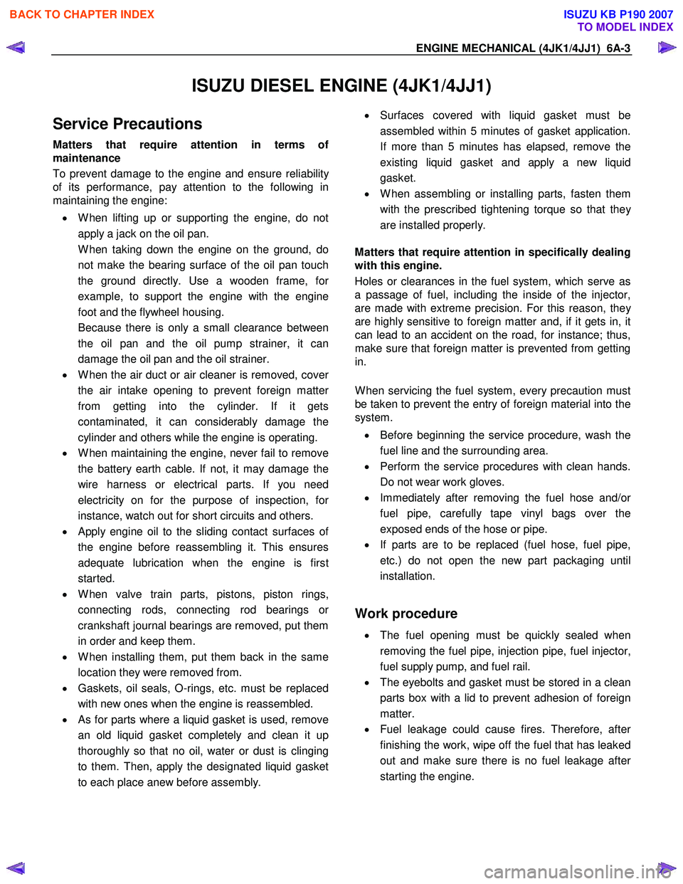
ISUZU DIESEL ENGINE (4JK1/4JJ1)
Service Precautions
Matters that require attention in terms of
maintenance
To prevent damage to the engine and ensure reliabilit
y
of its performance, pay attention to the following in
maintaining the engine:
• W hen lifting up or supporting the engine, do not
apply a jack on the oil pan.
W hen taking down the engine on the ground, do not make the bearing surface of the oil pan touch
the ground directly. Use a wooden frame, fo
r
example, to support the engine with the engine
foot and the flywheel housing.
Because there is only a small clearance between the oil pan and the oil pump strainer, it can
damage the oil pan and the oil strainer.
• W hen the air duct or air cleaner is removed, cove
r
the air intake opening to prevent foreign matter
from getting into the cylinder. If it gets
contaminated, it can considerably damage the
cylinder and others while the engine is operating.
• W hen maintaining the engine, never fail to remove
the battery earth cable. If not, it may damage the
wire harness or electrical parts. If you need
electricity on for the purpose of inspection, fo
r
instance, watch out for short circuits and others.
•
Apply engine oil to the sliding contact surfaces of
the engine before reassembling it. This ensures
adequate lubrication when the engine is first
started.
• W hen valve train parts, pistons, piston rings,
connecting rods, connecting rod bearings o
r
crankshaft journal bearings are removed, put them
in order and keep them.
• W hen installing them, put them back in the same
location they were removed from.
• Gaskets, oil seals, O-rings, etc. must be replaced
with new ones when the engine is reassembled.
•
As for parts where a liquid gasket is used, remove
an old liquid gasket completely and clean it up
thoroughly so that no oil, water or dust is clinging
to them. Then, apply the designated liquid gasket
to each place anew before assembly.
• Surfaces covered with liquid gasket must be
assembled within 5 minutes of gasket application.
If more than 5 minutes has elapsed, remove the
existing liquid gasket and apply a new liquid
gasket.
• W hen assembling or installing parts, fasten them
with the prescribed tightening torque so that the
y
are installed properly.
Matters that require attention in specifically dealing
with this engine.
Holes or clearances in the fuel system, which serve as
a passage of fuel, including the inside of the injector,
are made with extreme precision. For this reason, the
y
are highly sensitive to foreign matter and, if it gets in, it
can lead to an accident on the road, for instance; thus,
make sure that foreign matter is prevented from getting
in.
W hen servicing the fuel system, every precaution must
be taken to prevent the entry of foreign material into the
system.
• Before beginning the service procedure, wash the
fuel line and the surrounding area.
• Perform the service procedures with clean hands.
Do not wear work gloves.
• Immediately after removing the fuel hose and/o
r
fuel pipe, carefully tape vinyl bags over the
exposed ends of the hose or pipe.
• If parts are to be replaced (fuel hose, fuel pipe,
etc.) do not open the new part packaging until
installation.
Work procedure
• The fuel opening must be quickly sealed when
removing the fuel pipe, injection pipe, fuel injector,
fuel supply pump, and fuel rail.
• The eyebolts and gasket must be stored in a clean
parts box with a lid to prevent adhesion of foreign
matter.
• Fuel leakage could cause fires. Therefore, afte
r
finishing the work, wipe off the fuel that has leaked
out and make sure there is no fuel leakage afte
r
starting the engine.
BACK TO CHAPTER INDEX
TO MODEL INDEX
ISUZU KB P190 2007
Page 1543 of 6020
6C-2 FUEL SYSTEM (4JK1/4JJ1)
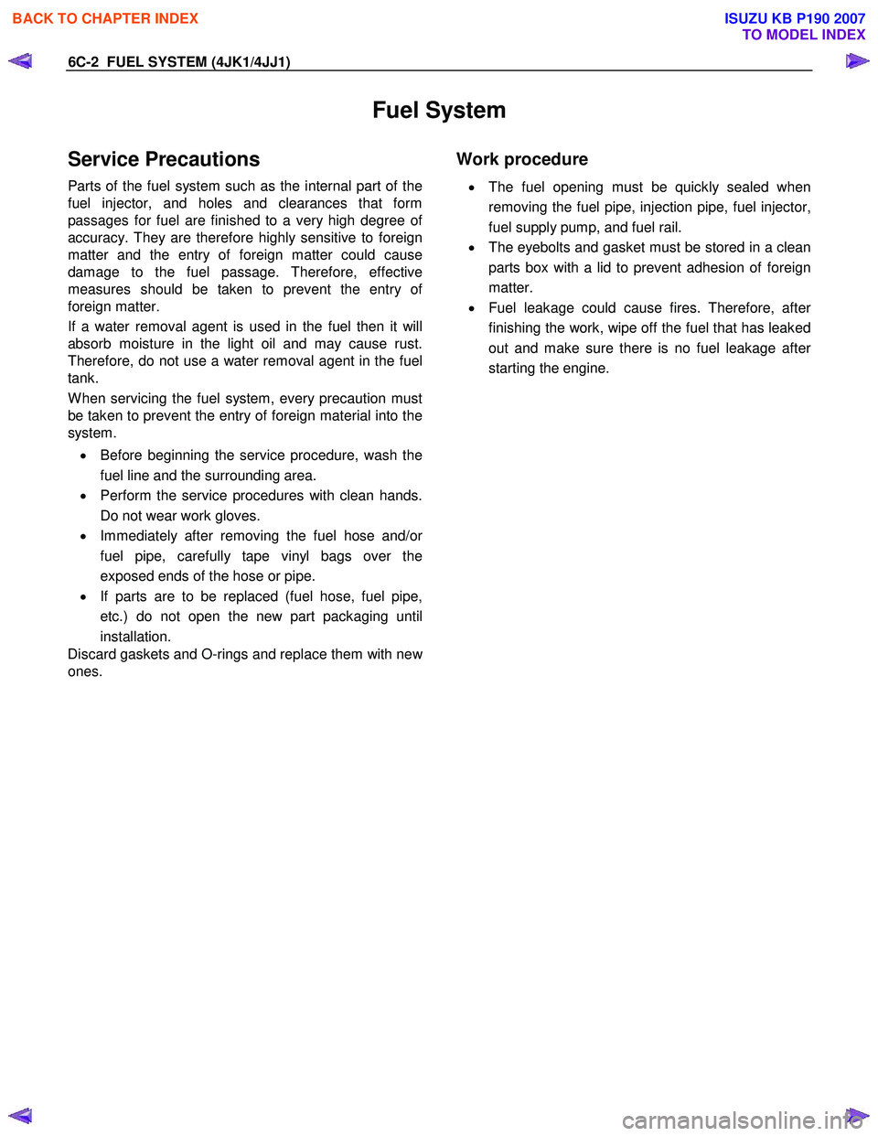
Fuel System
Service Precautions
Parts of the fuel system such as the internal part of the
fuel injector, and holes and clearances that form
passages for fuel are finished to a very high degree o
f
accuracy. They are therefore highly sensitive to foreign
matter and the entry of foreign matter could cause
damage to the fuel passage. Therefore, effective
measures should be taken to prevent the entry o
f
foreign matter.
If a water removal agent is used in the fuel then it will
absorb moisture in the light oil and may cause rust.
Therefore, do not use a water removal agent in the fuel
tank.
W hen servicing the fuel system, every precaution must
be taken to prevent the entry of foreign material into the
system.
• Before beginning the service procedure, wash the
fuel line and the surrounding area.
• Perform the service procedures with clean hands.
Do not wear work gloves.
• Immediately after removing the fuel hose and/o
r
fuel pipe, carefully tape vinyl bags over the
exposed ends of the hose or pipe.
• If parts are to be replaced (fuel hose, fuel pipe,
etc.) do not open the new part packaging until
installation.
Discard gaskets and O-rings and replace them with ne
w
ones.
Work procedure
•
The fuel opening must be quickly sealed when
removing the fuel pipe, injection pipe, fuel injector,
fuel supply pump, and fuel rail.
• The eyebolts and gasket must be stored in a clean
parts box with a lid to prevent adhesion of foreign
matter.
• Fuel leakage could cause fires. Therefore, afte
r
finishing the work, wipe off the fuel that has leaked
out and make sure there is no fuel leakage afte
r
starting the engine.
BACK TO CHAPTER INDEX
TO MODEL INDEX
ISUZU KB P190 2007
Page 3153 of 6020
Engine Cooling – V6 Engine Page 6B1–18
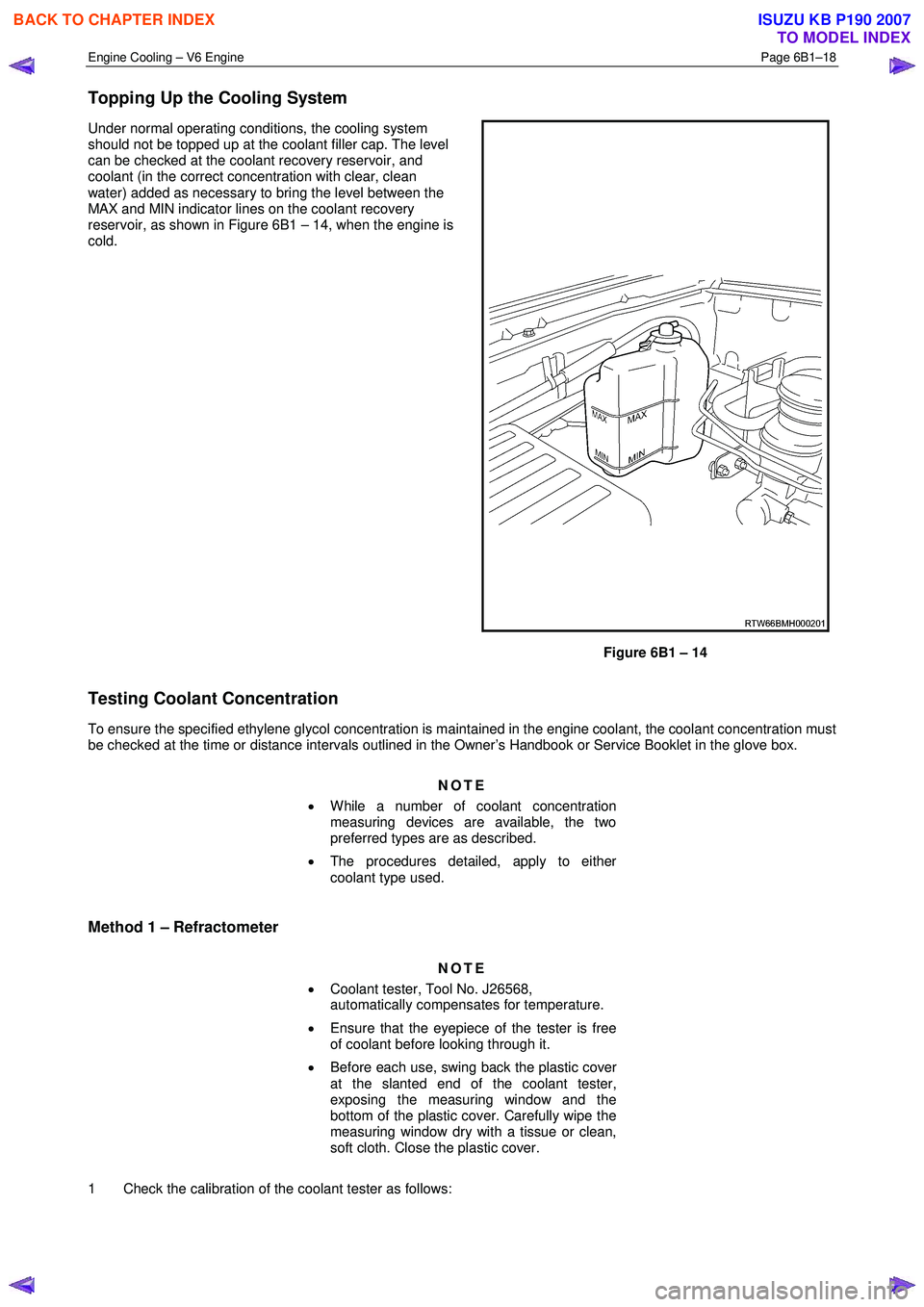
Topping Up the Cooling System
Under normal operating conditions, the cooling system
should not be topped up at the coolant filler cap. The level
can be checked at the coolant recovery reservoir, and
coolant (in the correct concentration with clear, clean
water) added as necessary to bring the level between the
MAX and MIN indicator lines on the coolant recovery
reservoir, as shown in Figure 6B1 – 14, when the engine is
cold.
Figure 6B1 – 14
Testing Coolant Concentration
To ensure the specified ethylene glycol concentration is maintained in the engine coolant, the coolant concentration must
be checked at the time or distance intervals outlined in the Owner’s Handbook or Service Booklet in the glove box.
NOTE
• While a number of coolant concentration
measuring devices are available, the two
preferred types are as described.
• The procedures detailed, apply to either
coolant type used.
Method 1 – Refractometer
NOTE
• Coolant tester, Tool No. J26568,
automatically compensates for temperature.
• Ensure that the eyepiece of the tester is free
of coolant before looking through it.
• Before each use, swing back the plastic cover
at the slanted end of the coolant tester,
exposing the measuring window and the
bottom of the plastic cover. Carefully wipe the
measuring window dry with a tissue or clean,
soft cloth. Close the plastic cover.
1 Check the calibration of the coolant tester as follows:
BACK TO CHAPTER INDEX
TO MODEL INDEX
ISUZU KB P190 2007
Page 5117 of 6020
ELECTRICAL-BODY AND CHASSIS 8A-179
RTW 78ASH002901
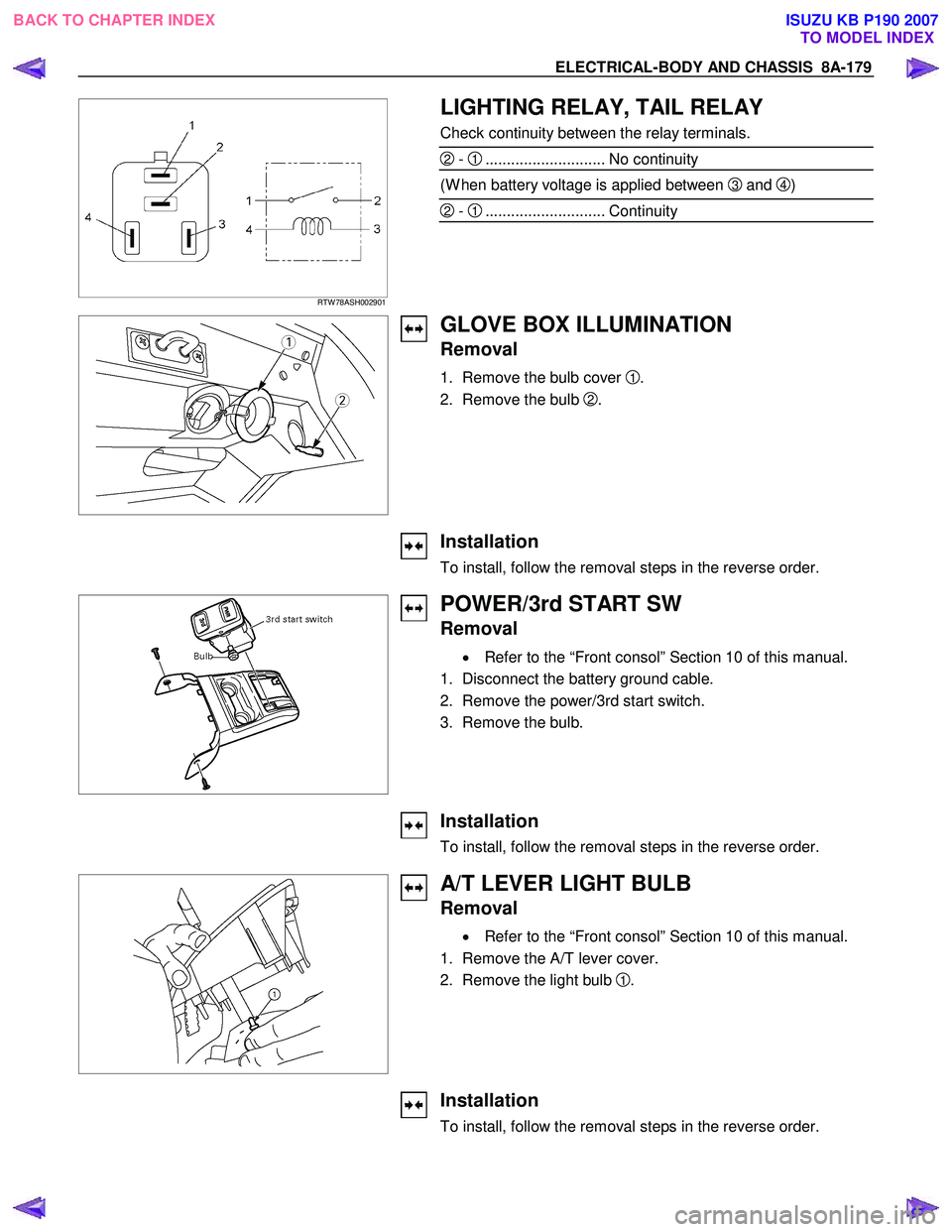
LIGHTING RELAY, TAIL RELAY
Check continuity between the relay terminals.
2 - 1............................ No continuity
(W hen battery voltage is applied between 3 and 4)
2 - 1............................ Continuity
GLOVE BOX ILLUMINATION
Removal
1. Remove the bulb cover 1.
2. Remove the bulb
2.
Installation
To install, follow the removal steps in the reverse order.
POWER/3rd START SW
Removal
• Refer to the “Front consol” Section 10 of this manual.
1. Disconnect the battery ground cable.
2. Remove the power/3rd start switch.
3. Remove the bulb.
Installation
To install, follow the removal steps in the reverse order.
A/T LEVER LIGHT BULB
Removal
• Refer to the “Front consol” Section 10 of this manual.
1. Remove the A/T lever cover.
2. Remove the light bulb
1.
Installation
To install, follow the removal steps in the reverse order.
BACK TO CHAPTER INDEX TO MODEL INDEXISUZU KB P190 2007
Page 5480 of 6020
8A-542 ELECTRICAL-BODY AND CHASSIS
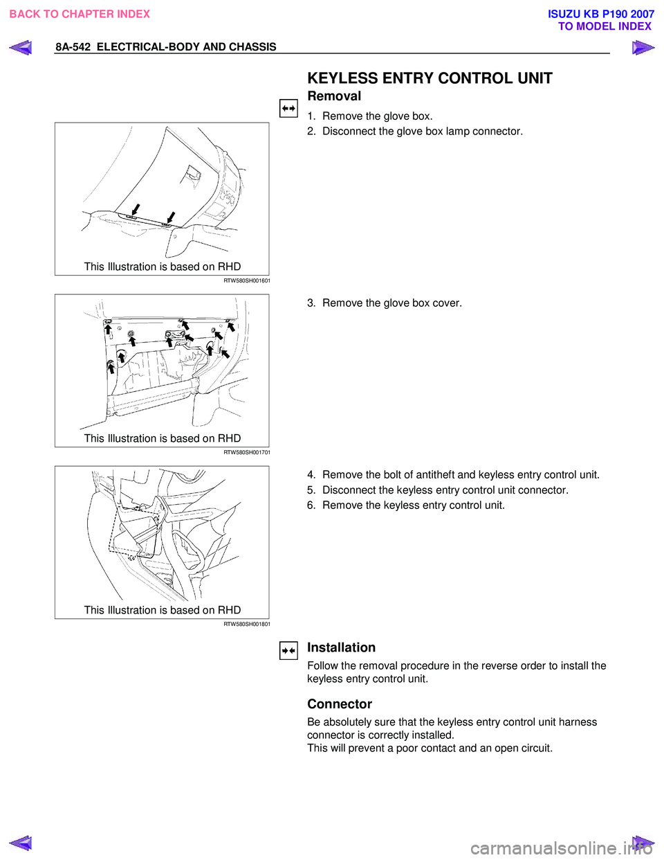
KEYLESS ENTRY CONTROL UNIT
Removal
1. Remove the glove box.
This Illustration is based on RHD
RTW 580SH001601
2. Disconnect the glove box lamp connector.
This Illustration is based on RHD
RTW 580SH001701
3. Remove the glove box cover.
This Illustration is based on RHD
RTW 580SH001801
4. Remove the bolt of antitheft and keyless entry control unit.
5. Disconnect the keyless entry control unit connector.
6. Remove the keyless entry control unit.
Installation
Follow the removal procedure in the reverse order to install the
keyless entry control unit.
Connector
Be absolutely sure that the keyless entry control unit harness
connector is correctly installed.
This will prevent a poor contact and an open circuit.
BACK TO CHAPTER INDEX TO MODEL INDEXISUZU KB P190 2007