tire type ISUZU KB P190 2007 Workshop Repair Manual
[x] Cancel search | Manufacturer: ISUZU, Model Year: 2007, Model line: KB P190, Model: ISUZU KB P190 2007Pages: 6020, PDF Size: 70.23 MB
Page 250 of 6020
3A-2 FRONT ALIGNMENT
Front End Alignment Inspection and
Adjustment
General Description
“Front End Alignment” refers to the angular relationship
between the front wheels, the front suspension attaching parts
and the ground.
Proper front end alignment must be maintained in order to
insure efficient steering, good directional stability and to
prevent abnormal tire wear.
The most important factors of front end alignment are wheel
toe-in, wheel camber and axle caster.
Camber:
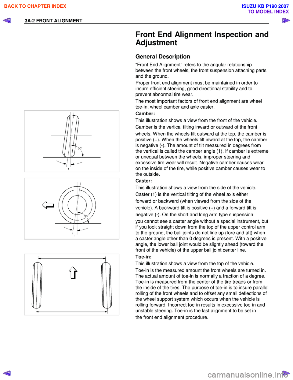
This illustration shows a view from the front of the vehicle.
Camber is the vertical tilting inward or outward of the front
wheels. W hen the wheels tilt outward at the top, the camber is
positive (+). W hen the wheels tilt inward at the top, the camber
is negative (-). The amount of tilt measured in degrees from
the vertical is called the camber angle (1). If camber is extreme
or unequal between the wheels, improper steering and
excessive tire wear will result. Negative camber causes wear
on the inside of the tire, while positive camber causes wear to
the outside.
Caster:
This illustration shows a view from the side of the vehicle.
Caster (1) is the vertical tilting of the wheel axis either
forward or backward (when viewed from the side of the
vehicle). A backward tilt is positive (+) and a forward tilt is
negative (-). On the short and long arm type suspension
you cannot see a caster angle without a special instrument, but
if you look straight down from the top of the upper control arm
to the ground, the ball joints do not line up (fore and aft) when
a caster angle other than 0 degrees is present. W ith a positive
angle, the lower ball joint would be slightly ahead (toward the
front of the vehicle) of the upper ball joint center line.
Toe-in:
This illustration shows a view from the top of the vehicle.
Toe-in is the measured amount the front wheels are turned in.
The actual amount of toe-in is normally a fraction of a degree.
Toe-in is measured from the center of the tire treads or from
the inside of the tires. The purpose of toe-in is to insure parallel
rolling of the front wheels and to offset any small deflections of
the wheel support system which occurs when the vehicle is
rolling forward. Incorrect toe-in results in excessive toe-in and
unstable steering. Toe-in is the last alignment to be set in
the front end alignment procedure.
BACK TO CHAPTER INDEX
TO MODEL INDEX
ISUZU KB P190 2007
Page 412 of 6020
3E-8 WHEELS AND TIRES
INSPECTION AND REPAIR
Make necessary correction or parts replacement if wear, damage or any other abnormal conditions are found
through inspection.
Visual Check
Inspect all disassembled parts for wear, damage or other
abnormal conditions.
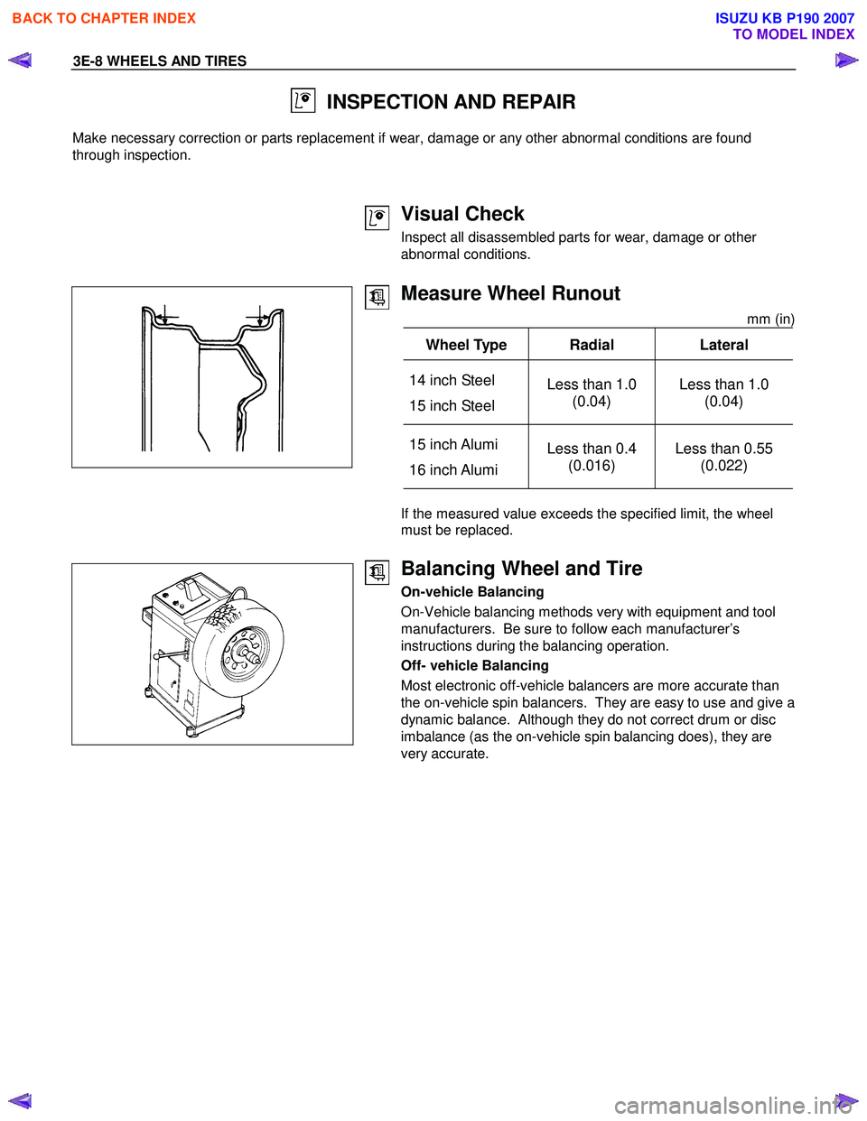
Measure Wheel Runout
mm (in)
Wheel Type Radial Lateral
14 inch Steel
15 inch Steel Less than 1.0
(0.04) Less than 1.0
(0.04)
15 inch Alumi
16 inch Alumi Less than 0.4
(0.016) Less than 0.55
(0.022)
If the measured value exceeds the specified limit, the wheel
must be replaced.
Balancing Wheel and Tire
On-vehicle Balancing
On-Vehicle balancing methods very with equipment and tool
manufacturers. Be sure to follow each manufacturer’s
instructions during the balancing operation.
Off- vehicle Balancing
Most electronic off-vehicle balancers are more accurate than
the on-vehicle spin balancers. They are easy to use and give a
dynamic balance. Although they do not correct drum or disc
imbalance (as the on-vehicle spin balancing does), they are
very accurate.
BACK TO CHAPTER INDEX
TO MODEL INDEX
ISUZU KB P190 2007
Page 451 of 6020
REAR AXLE 4B-7
REAR AXLE ASSEMBLY
General Description
A03R300001
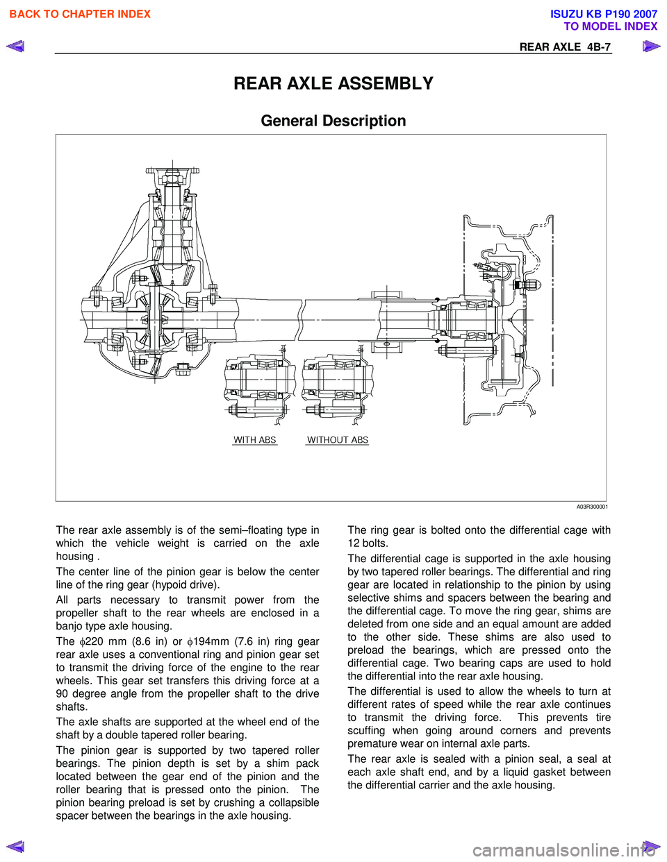
The rear axle assembly is of the semi–floating type in
which the vehicle weight is carried on the axle
housing .
The center line of the pinion gear is below the cente
r
line of the ring gear (hypoid drive).
All parts necessary to transmit power from the
propeller shaft to the rear wheels are enclosed in a
banjo type axle housing.
The φ220 mm (8.6 in) or φ194mm (7.6 in) ring gea
r
rear axle uses a conventional ring and pinion gear set
to transmit the driving force of the engine to the rea
r
wheels. This gear set transfers this driving force at a
90 degree angle from the propeller shaft to the drive
shafts.
The axle shafts are supported at the wheel end of the
shaft by a double tapered roller bearing.
The pinion gear is supported by two tapered rolle
r
bearings. The pinion depth is set by a shim pack
located between the gear end of the pinion and the
roller bearing that is pressed onto the pinion. The
pinion bearing preload is set by crushing a collapsible
spacer between the bearings in the axle housing.
The ring gear is bolted onto the differential cage with
12 bolts.
The differential cage is supported in the axle housing
by two tapered roller bearings. The differential and ring
gear are located in relationship to the pinion by using
selective shims and spacers between the bearing and
the differential cage. To move the ring gear, shims are
deleted from one side and an equal amount are added
to the other side. These shims are also used to
preload the bearings, which are pressed onto the
differential cage. Two bearing caps are used to hold
the differential into the rear axle housing.
The differential is used to allow the wheels to turn at
different rates of speed while the rear axle continues
to transmit the driving force. This prevents tire
scuffing when going around corners and prevents
premature wear on internal axle parts.
The rear axle is sealed with a pinion seal, a seal at
each axle shaft end, and by a liquid gasket between
the differential carrier and the axle housing.
BACK TO CHAPTER INDEX
TO MODEL INDEX
ISUZU KB P190 2007
Page 734 of 6020
BRAKES 5C-35
9. Front Hub and Disc Assembly
For the removal procedure, refer to Section 4C “FRONT
W HEEL DRIVE”.
Important Operations - Installation
9. Front Hub and Disc Assembly
For the installation procedure, refer to the front hub and disc
reassembly procedure in Section 4C “FRONT W HEEL
DRIVE”.
RUW 55CSH000101
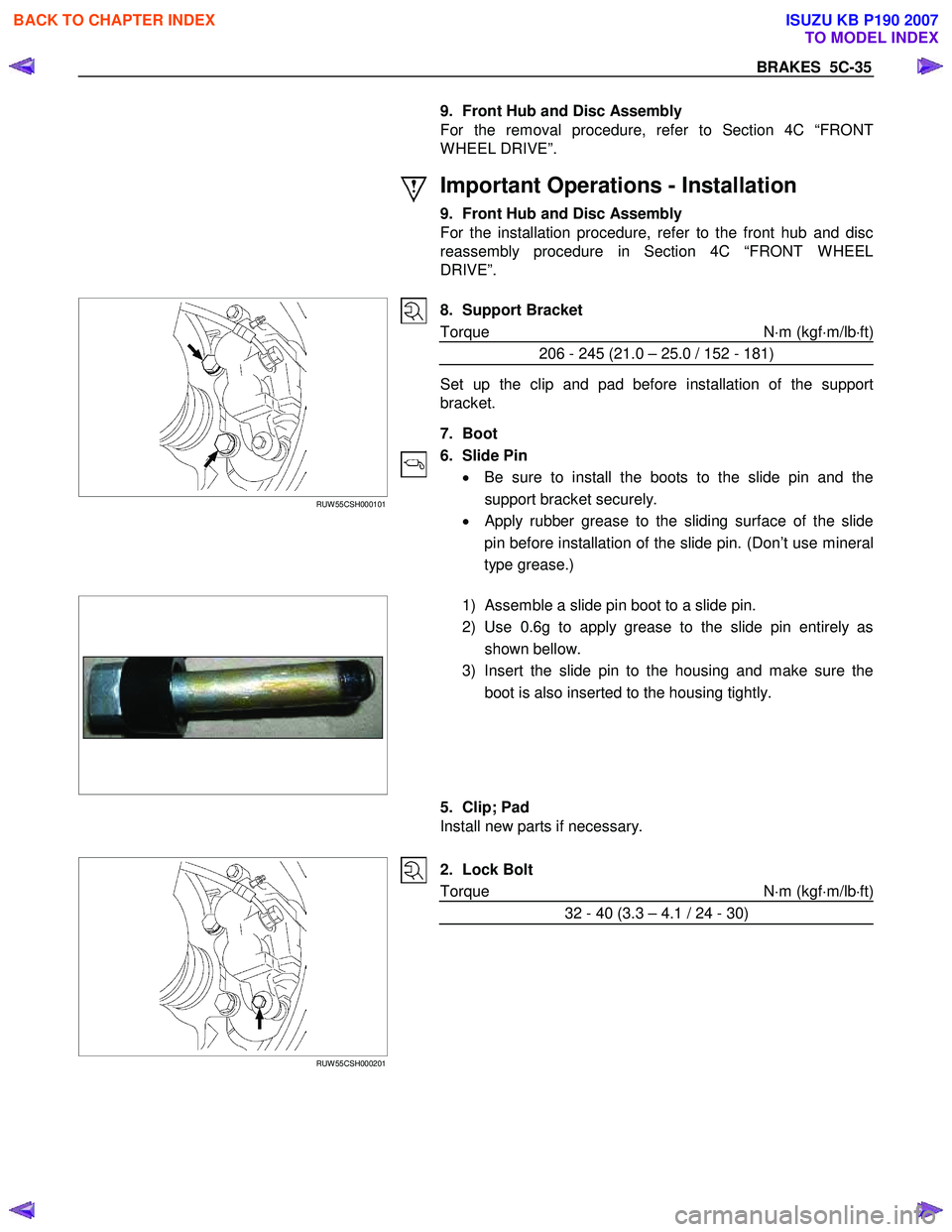
8. Support Bracket
Torque N ⋅m (kgf ⋅m/lb ⋅ft)
206 - 245 (21.0 – 25.0 / 152 - 181)
Set up the clip and pad before installation of the support
bracket.
7. Boot
6. Slide Pin • Be sure to install the boots to the slide pin and the
support bracket securely.
•
Apply rubber grease to the sliding surface of the slide
pin before installation of the slide pin. (Don’t use mineral
type grease.)
1) Assemble a slide pin boot to a slide pin.
2) Use 0.6g to apply grease to the slide pin entirely as shown bellow.
3) Insert the slide pin to the housing and make sure the boot is also inserted to the housing tightly.
5. Clip; Pad
Install new parts if necessary.
RUW 55CSH000201
2. Lock Bolt
Torque N ⋅m (kgf ⋅m/lb ⋅ft)
32 - 40 (3.3 – 4.1 / 24 - 30)
BACK TO CHAPTER INDEX
TO MODEL INDEX
ISUZU KB P190 2007
Page 780 of 6020
5D-10 PARKING BRAKE SYSTEM
Removal
1. Remove wheel and tire.
2. Remove brake drum.
3. Remove tension pin and shoe clamp spring.
4. Remove return spring.
5. Remove shoe assembly with parking brake lever.
6. Remove shoe assembly with adjuster lever and spring.
7. Remove parking brake inner cable from parking brake lever.
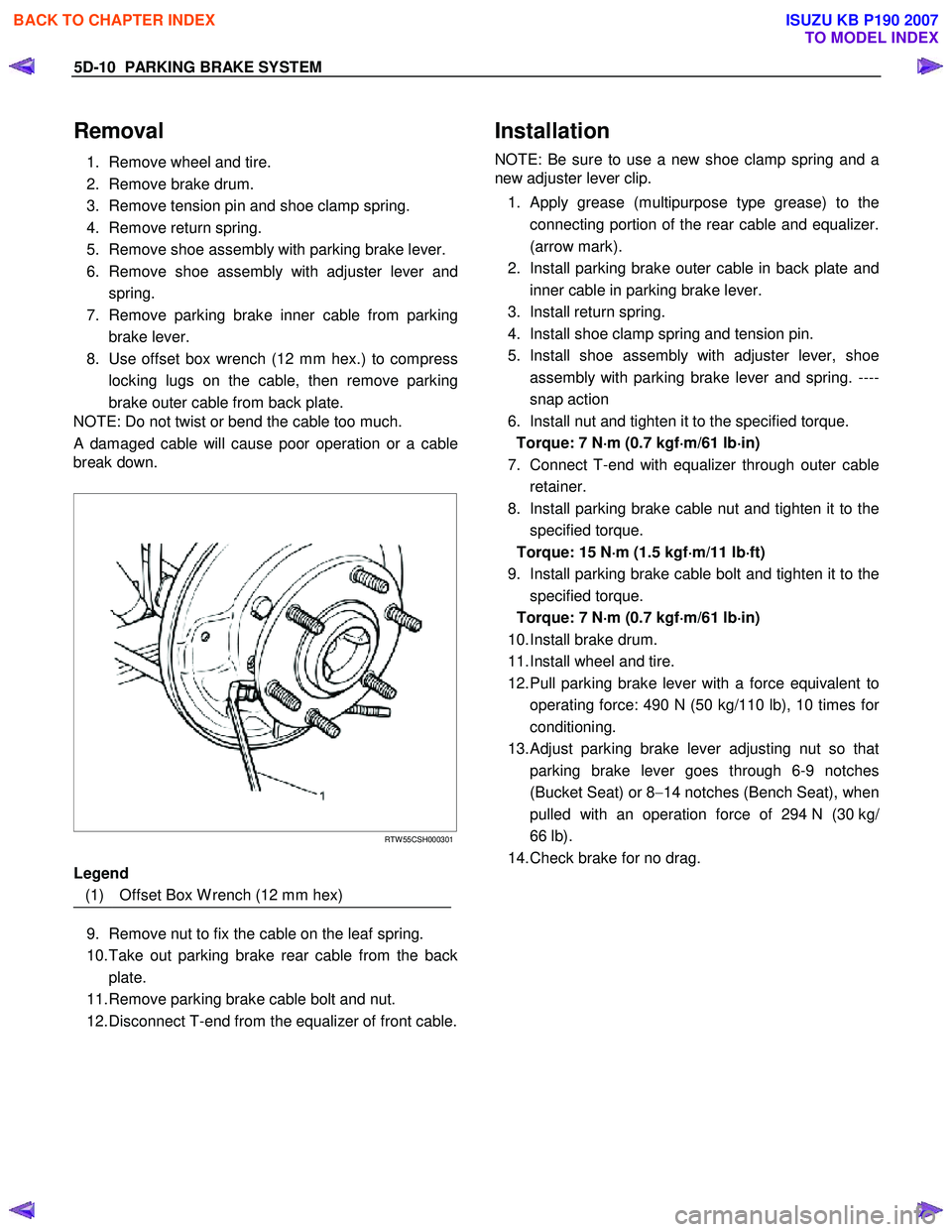
8. Use offset box wrench (12 mm hex.) to compress locking lugs on the cable, then remove parking
brake outer cable from back plate.
NOTE: Do not twist or bend the cable too much.
A damaged cable will cause poor operation or a cable
break down.
RTW 55CSH000301
Legend
(1) Offset Box W rench (12 mm hex)
9. Remove nut to fix the cable on the leaf spring.
10. Take out parking brake rear cable from the back plate.
11. Remove parking brake cable bolt and nut.
12. Disconnect T-end from the equalizer of front cable.
Installation
NOTE: Be sure to use a new shoe clamp spring and a
new adjuster lever clip.
1. Apply grease (multipurpose type grease) to the connecting portion of the rear cable and equalizer.
(arrow mark).
2. Install parking brake outer cable in back plate and inner cable in parking brake lever.
3. Install return spring.
4. Install shoe clamp spring and tension pin.
5. Install shoe assembly with adjuster lever, shoe assembly with parking brake lever and spring. ----
snap action
6. Install nut and tighten it to the specified torque. Torque: 7 N ⋅
⋅⋅
⋅
m (0.7 kgf ⋅
⋅⋅
⋅
m/61 lb ⋅
⋅⋅
⋅
in)
7. Connect T-end with equalizer through outer cable retainer.
8. Install parking brake cable nut and tighten it to the specified torque.
Torque: 15 N ⋅
⋅⋅
⋅
m (1.5 kgf ⋅
⋅⋅
⋅
m/11 lb ⋅
⋅⋅
⋅
ft)
9. Install parking brake cable bolt and tighten it to the specified torque.
Torque: 7 N ⋅
⋅⋅
⋅
m (0.7 kgf ⋅
⋅⋅
⋅
m/61 lb ⋅
⋅⋅
⋅
in)
10. Install brake drum.
11. Install wheel and tire.
12. Pull parking brake lever with a force equivalent to operating force: 490 N (50 kg/110 lb), 10 times fo
r
conditioning.
13.
Adjust parking brake lever adjusting nut so that
parking brake lever goes through 6-9 notches
(Bucket Seat) or 8 −14 notches (Bench Seat), when
pulled with an operation force of 294 N (30 kg/
66 lb).
14. Check brake for no drag.
BACK TO CHAPTER INDEX
TO MODEL INDEX
ISUZU KB P190 2007
Page 955 of 6020
ENGINE COOLING 6B – 11
Inspection and Repair
The water pump is not disassembled type.
Make necessary parts replacement if extreme wear or
damage is found during inspection. Should any of the
following problems occur, the entire water pump assembly
must be replaced.
・ Cracks in the water pump body
・ Coolant leakage from the seal unit
・ Excessive radial play or abnormal noise in the fan center
when rotate by hand
・ Excessive thrust play in the fan center (Standard play: less
than 0.2mm)
・ Cracks or corrosion in the impeller
Installation
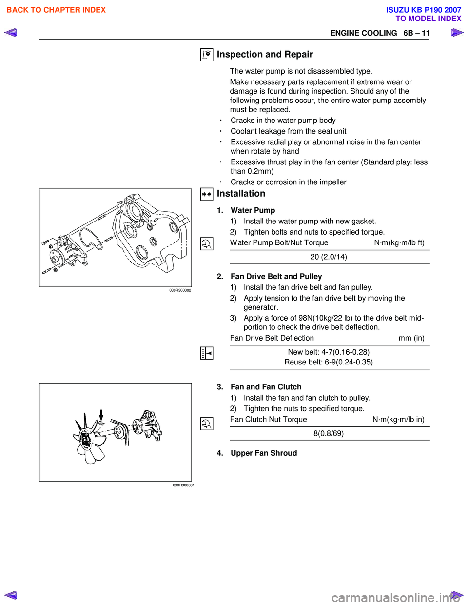
1. Water Pump
1) Install the water pump with new gasket.
2) Tighten bolts and nuts to specified torque.
W ater Pump Bolt/Nut Torque N·m(kg·m/lb ft)
20 (2.0/14)
2. Fan Drive Belt and Pulley
1) Install the fan drive belt and fan pulley.
2) Apply tension to the fan drive belt by moving the generator.
3) Apply a force of 98N(10kg/22 lb) to the drive belt mid- portion to check the drive belt deflection.
Fan Drive Belt Deflection mm (in)
New belt: 4-7(0.16-0.28)
Reuse belt: 6-9(0.24-0.35)
030R300002
030R300001
3. Fan and Fan Clutch
1) Install the fan and fan clutch to pulley.
2) Tighten the nuts to specified torque.
Fan Clutch Nut Torque N·m(kg·m/lb in)
8(0.8/69)
4. Upper Fan Shroud
BACK TO CHAPTER INDEX
TO MODEL INDEX
ISUZU KB P190 2007
Page 1305 of 6020
Engine Control System (4JH1) 6E-271
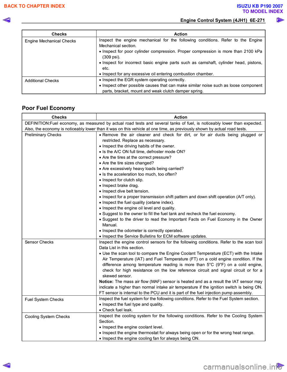
Checks Action
Engine Mechanical Checks Inspect the engine mechanical for the following conditions. Refer to the Engine
Mechanical section.
• Inspect for poor cylinder compression. Proper compression is more than 2100 kPa
(309 psi).
• Inspect for incorrect basic engine parts such as camshaft, cylinder head, pistons,
etc.
• Inspect for any excessive oil entering combustion chamber.
Additional Checks •
Inspect the EGR system operating correctly.
• Inspect other possible causes that can make similar noise such as loose component
parts, bracket, mount and weak clutch damper spring.
Poor Fuel Economy
Checks Action
DEFINITION:Fuel economy, as measured by actual road tests and several tanks of fuel, is noticeably lower than expected.
Also, the economy is noticeably lower than it was on this vehicle at one time, as previously shown by actual road tests.
Preliminary Checks • Remove the air cleaner and check for dirt, or for air ducts being plugged or
restricted. Replace as necessary.
• Inspect the driving habits of the owner.
• Is the A/C ON full time, defroster mode ON?
• Are the tires at the correct pressure?
• Are the tire sizes changed?
• Are excessively heavy loads being carried?
• Is the acceleration too much, too often?
• Inspect for clutch slip.
• Inspect brake drag.
• Inspect dive belt tension.
• Inspect for a proper transmission shift pattern and down shift operation (A/T only).
• Inspect the fuel quality (cetane index).
• Inspect the engine oil level and quality.
• Suggest to the owner to fill the fuel tank and recheck the fuel economy.
• Suggest to the driver to read the Important Facts on Fuel Economy in the Owner
Manual.
• Inspect the odometer is correctly operated.
• Inspect the Service Bulletins for ECM software updates.
Sensor Checks Inspect the engine control sensors for the following conditions. Refer to the scan tool
Data List in this section.
• Use the scan tool to compare the Engine Coolant Temperature (ECT) with the Intake
Air Temperature (IAT) and Fuel Temperature (FT) on a cold engine condition. If the
difference among temperature reading is more than 5°C (9°F) on a cold engine,
check for high resistance on the low reference circuit and signal circuit or for a
skewed sensor.
Notice: The mass air flow (MAF) sensor is heated and as a result the IAT sensor may
indicate a higher than normal intake air temperature if the ignition switch is being ON.
FT sensor is internal to the PCU and it is part of the fuel injection pump assembly.
Fuel System Checks Inspect the fuel system for the following conditions. Refer to the Fuel System section.
• Inspect the fuel type and quality.
• Check fuel leak.
Cooling System Checks Inspect the cooling system for the following conditions. Refer to the Cooling System
Section.
• Inspect the engine coolant level.
• Inspect the engine thermostat for always being open or for the wrong heat range.
• Inspect the engine cooling fan for always being ON.
BACK TO CHAPTER INDEX
TO MODEL INDEX
ISUZU KB P190 2007
Page 1310 of 6020
6E-276 Engine Control System (4JH1)
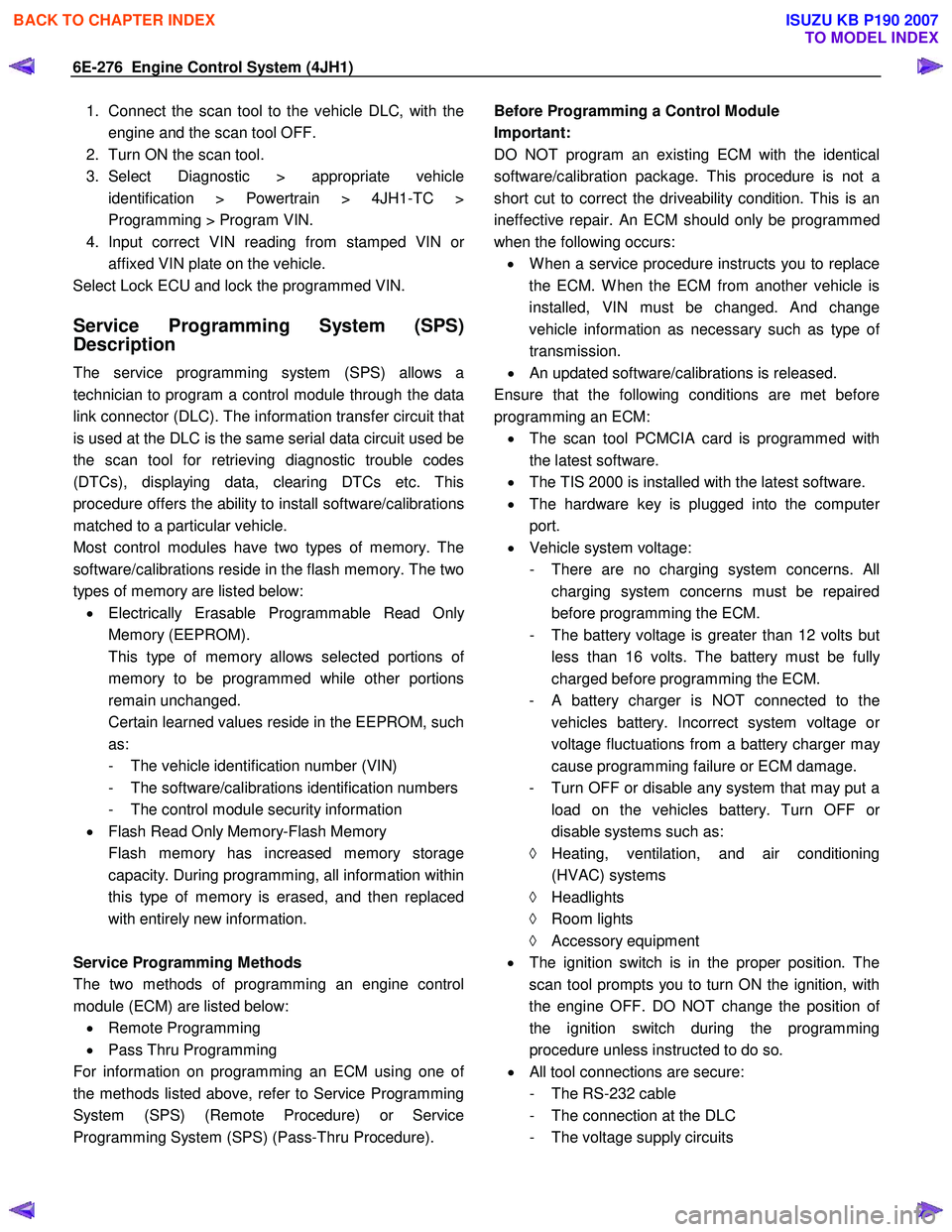
1. Connect the scan tool to the vehicle DLC, with theengine and the scan tool OFF.
2. Turn ON the scan tool.
3. Select Diagnostic > appropriate vehicle identification > Powertrain > 4JH1-TC >
Programming > Program VIN.
4. Input correct VIN reading from stamped VIN o
r
affixed VIN plate on the vehicle.
Select Lock ECU and lock the programmed VIN.
Service Programming System (SPS)
Description
The service programming system (SPS) allows a
technician to program a control module through the data
link connector (DLC). The information transfer circuit that
is used at the DLC is the same serial data circuit used be
the scan tool for retrieving diagnostic trouble codes
(DTCs), displaying data, clearing DTCs etc. This
procedure offers the ability to install software/calibrations
matched to a particular vehicle.
Most control modules have two types of memory. The
software/calibrations reside in the flash memory. The two
types of memory are listed below: • Electrically Erasable Programmable Read Onl
y
Memory (EEPROM).
This type of memory allows selected portions o
f
memory to be programmed while other portions
remain unchanged.
Certain learned values reside in the EEPROM, such as:
- The vehicle identification number (VIN)
- The software/calibrations identification numbers
- The control module security information
• Flash Read Only Memory-Flash Memory
Flash memory has increased memory storage capacity. During programming, all information within
this type of memory is erased, and then replaced
with entirely new information.
Service Programming Methods
The two methods of programming an engine control
module (ECM) are listed below: • Remote Programming
• Pass Thru Programming
For information on programming an ECM using one o
f
the methods listed above, refer to Service Programming
System (SPS) (Remote Procedure) or Service
Programming System (SPS) (Pass-Thru Procedure).
Before Programming a Control Module
Important:
DO NOT program an existing ECM with the identical
software/calibration package. This procedure is not a
short cut to correct the driveability condition. This is an
ineffective repair. An ECM should only be programmed
when the following occurs: • W hen a service procedure instructs you to replace
the ECM. W hen the ECM from another vehicle is
installed, VIN must be changed. And change
vehicle information as necessary such as type o
f
transmission.
• An updated software/calibrations is released.
Ensure that the following conditions are met before
programming an ECM: • The scan tool PCMCIA card is programmed with
the latest software.
• The TIS 2000 is installed with the latest software.
• The hardware key is plugged into the compute
r
port.
• Vehicle system voltage:
- There are no charging system concerns. All charging system concerns must be repaired
before programming the ECM.
- The battery voltage is greater than 12 volts bu
t
less than 16 volts. The battery must be fully
charged before programming the ECM.
-
A battery charger is NOT connected to the
vehicles battery. Incorrect system voltage o
r
voltage fluctuations from a battery charger may
cause programming failure or ECM damage.
- Turn OFF or disable any system that may put a load on the vehicles battery. Turn OFF o
r
disable systems such as:
◊ Heating, ventilation, and air conditioning
(HVAC) systems
◊ Headlights
◊ Room lights
◊ Accessory equipment
• The ignition switch is in the proper position. The
scan tool prompts you to turn ON the ignition, with
the engine OFF. DO NOT change the position o
f
the ignition switch during the programming
procedure unless instructed to do so.
• All tool connections are secure:
- The RS-232 cable
- The connection at the DLC
- The voltage supply circuits
BACK TO CHAPTER INDEX
TO MODEL INDEX
ISUZU KB P190 2007
Page 1532 of 6020
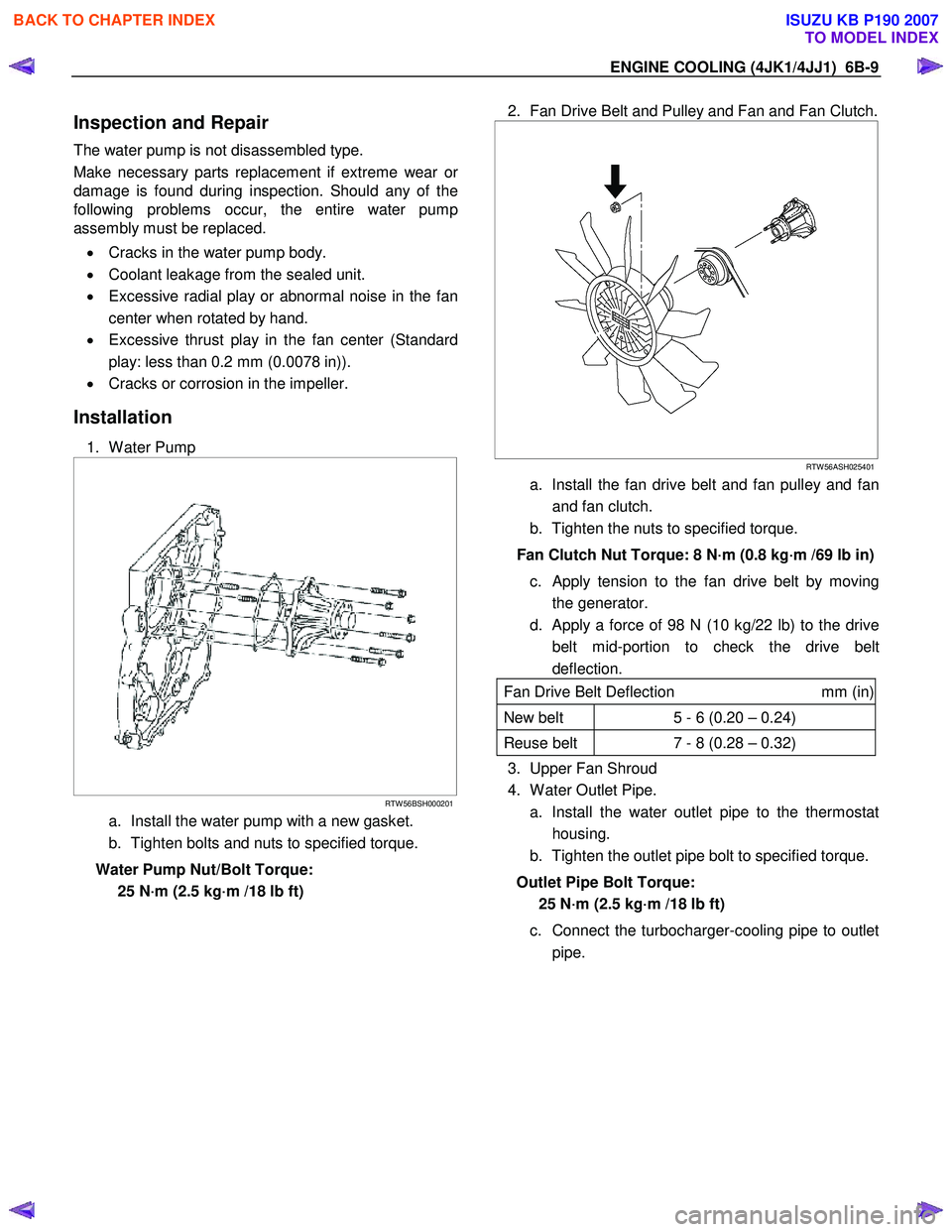
ENGINE COOLING (4JK1/4JJ1) 6B-9
Inspection and Repair
The water pump is not disassembled type.
Make necessary parts replacement if extreme wear o
r
damage is found during inspection. Should any of the
following problems occur, the entire water pump
assembly must be replaced.
• Cracks in the water pump body.
• Coolant leakage from the sealed unit.
• Excessive radial play or abnormal noise in the fan
center when rotated by hand.
• Excessive thrust play in the fan center (Standard
play: less than 0.2 mm (0.0078 in)).
• Cracks or corrosion in the impeller.
Installation
1. W ater Pump
RTW 56BSH000201
a. Install the water pump with a new gasket.
b. Tighten bolts and nuts to specified torque.
Water Pump Nut/Bolt Torque: 25 N·m (2.5 kg·m /18 lb ft)
2. Fan Drive Belt and Pulley and Fan and Fan Clutch.
RTW 56ASH025401
a. Install the fan drive belt and fan pulley and fan
and fan clutch.
b. Tighten the nuts to specified torque.
Fan Clutch Nut Torque: 8 N·m (0.8 kg·m /69 lb in) c. Apply tension to the fan drive belt by moving the generator.
d. Apply a force of 98 N (10 kg/22 lb) to the drive belt mid-portion to check the drive belt
deflection.
Fan Drive Belt Deflection mm (in)
New belt 5 - 6 (0.20 – 0.24)
Reuse belt 7 - 8 (0.28 – 0.32)
3. Upper Fan Shroud
4. W ater Outlet Pipe.
a. Install the water outlet pipe to the thermostat housing.
b. Tighten the outlet pipe bolt to specified torque.
Outlet Pipe Bolt Torque: 25 N·m (2.5 kg·m /18 lb ft)
c. Connect the turbocharger-cooling pipe to outlet pipe.
BACK TO CHAPTER INDEX
TO MODEL INDEX
ISUZU KB P190 2007
Page 1826 of 6020
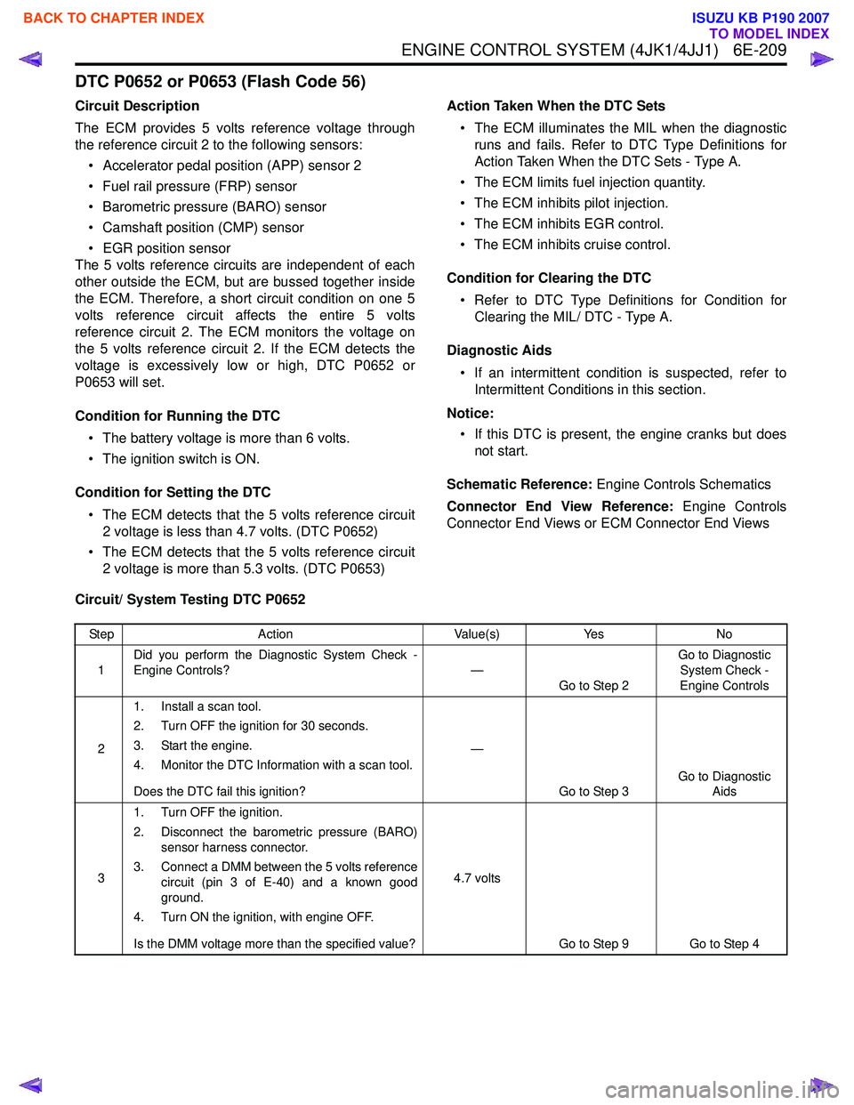
ENGINE CONTROL SYSTEM (4JK1/4JJ1) 6E-209
DTC P0652 or P0653 (Flash Code 56)
Circuit Description
The ECM provides 5 volts reference voltage through
the reference circuit 2 to the following sensors:
• Accelerator pedal position (APP) sensor 2
• Fuel rail pressure (FRP) sensor
• Barometric pressure (BARO) sensor
• Camshaft position (CMP) sensor
• EGR position sensor
The 5 volts reference circuits are independent of each
other outside the ECM, but are bussed together inside
the ECM. Therefore, a short circuit condition on one 5
volts reference circuit affects the entire 5 volts
reference circuit 2. The ECM monitors the voltage on
the 5 volts reference circuit 2. If the ECM detects the
voltage is excessively low or high, DTC P0652 or
P0653 will set.
Condition for Running the DTC • The battery voltage is more than 6 volts.
• The ignition switch is ON.
Condition for Setting the DTC • The ECM detects that the 5 volts reference circuit 2 voltage is less than 4.7 volts. (DTC P0652)
• The ECM detects that the 5 volts reference circuit 2 voltage is more than 5.3 volts. (DTC P0653) Action Taken When the DTC Sets
• The ECM illuminates the MIL when the diagnostic runs and fails. Refer to DTC Type Definitions for
Action Taken When the DTC Sets - Type A.
• The ECM limits fuel injection quantity.
• The ECM inhibits pilot injection.
• The ECM inhibits EGR control.
• The ECM inhibits cruise control.
Condition for Clearing the DTC • Refer to DTC Type Definitions for Condition for Clearing the MIL/ DTC - Type A.
Diagnostic Aids • If an intermittent condition is suspected, refer to Intermittent Conditions in this section.
Notice: • If this DTC is present, the engine cranks but does not start.
Schematic Reference: Engine Controls Schematics
Connector End View Reference: Engine Controls
Connector End Views or ECM Connector End Views
Circuit/ System Testing DTC P0652
Step Action Value(s)Yes No
1 Did you perform the Diagnostic System Check -
Engine Controls? —
Go to Step 2 Go to Diagnostic
System Check -
Engine Controls
2 1. Install a scan tool.
2. Turn OFF the ignition for 30 seconds.
3. Start the engine.
4. Monitor the DTC Information with a scan tool.
Does the DTC fail this ignition? —
Go to Step 3 Go to Diagnostic
Aids
3 1. Turn OFF the ignition.
2. Disconnect the barometric pressure (BARO) sensor harness connector.
3. Connect a DMM between the 5 volts reference circuit (pin 3 of E-40) and a known good
ground.
4. Turn ON the ignition, with engine OFF.
Is the DMM voltage more than the specified value? 4.7 volts
Go to Step 9 Go to Step 4
BACK TO CHAPTER INDEX
TO MODEL INDEX
ISUZU KB P190 2007