ISUZU TF SERIES 2004 Workshop Manual
Manufacturer: ISUZU, Model Year: 2004, Model line: TF SERIES, Model: ISUZU TF SERIES 2004Pages: 4264, PDF Size: 72.63 MB
Page 1211 of 4264

ENGINE MECHANICAL 6A – 71
Cylinder Liner Grade Selection
Subtract the average cylinder body bore from the average
cylinder liner outside diameter to obtain the fitting interference.
Fitting Interference mm (in)
Standard
-0.0010*-0.019 (-0.00004*-0.0007)
* A minus (-) value indicates that the cylinder body bore is
smaller than the liner outside diameter.
Cylinder Body Bore Measurement
1. Take measurements at measuring point (1) across
positions 1-1 and 2-2.
Measuring Point (1):
4JA1T(L), 4JA1TC : 13,48,83,118,153 mm
(0.51,1.89,3.27,4.65,6.02 in)
4JH1TC : 18,53,88,123,158 mm (0.71,2.09,3.46,4.84,6.22
in)
Cylinder Liner Grade Selection and Standard
Fitting Interference
Accurately measured fitting interference and proper cylinder
liner grade selection are extremely important.
If the cylinder liner fitting interference is too small, engine
cooling efficiency will be adversely affected.
If the cylinder liner fitting interference is too large, it will be
difficult to insert the cylinder liner into the cylinder body.
012RY00013
012RY00014
012R300001
Page 1212 of 4264
6A – 72 ENGINE MECHANICAL
012RY00022
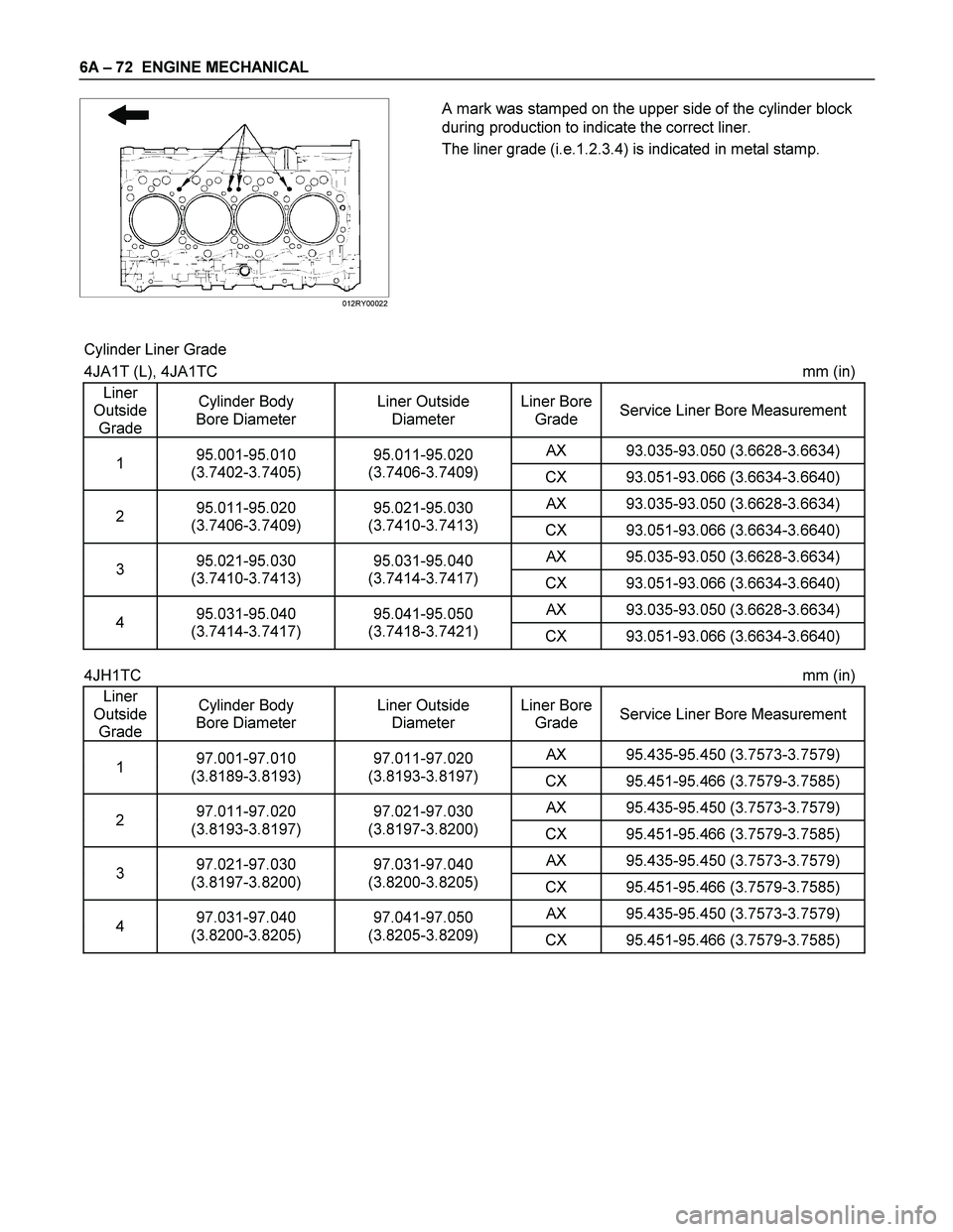
A mark was stamped on the upper side of the cylinder block
during production to indicate the correct liner.
The liner grade (i.e.1.2.3.4) is indicated in metal stamp.
Cylinder Liner Grade
4JA1T (L), 4JA1TC mm (in)
Liner
Outside
Grade Cylinder Body
Bore Diameter Liner Outside
Diameter Liner Bore
Grade Service Liner Bore Measurement
AX 93.035-93.050 (3.6628-3.6634) 1 95.001-95.010
(3.7402-3.7405) 95.011-95.020
(3.7406-3.7409)
CX 93.051-93.066 (3.6634-3.6640)
AX 93.035-93.050 (3.6628-3.6634) 2 95.011-95.020
(3.7406-3.7409) 95.021-95.030
(3.7410-3.7413)
CX 93.051-93.066 (3.6634-3.6640)
AX 95.035-93.050 (3.6628-3.6634) 3 95.021-95.030
(3.7410-3.7413) 95.031-95.040
(3.7414-3.7417)
CX 93.051-93.066 (3.6634-3.6640)
AX 93.035-93.050 (3.6628-3.6634) 4 95.031-95.040
(3.7414-3.7417) 95.041-95.050
(3.7418-3.7421)
CX 93.051-93.066 (3.6634-3.6640)
4JH1TC mm (in)
Liner
Outside
Grade Cylinder Body
Bore Diameter Liner Outside
Diameter Liner Bore
Grade Service Liner Bore Measurement
AX 95.435-95.450 (3.7573-3.7579) 1 97.001-97.010
(3.8189-3.8193) 97.011-97.020
(3.8193-3.8197)
CX 95.451-95.466 (3.7579-3.7585)
AX 95.435-95.450 (3.7573-3.7579) 2 97.011-97.020
(3.8193-3.8197) 97.021-97.030
(3.8197-3.8200)
CX 95.451-95.466 (3.7579-3.7585)
AX 95.435-95.450 (3.7573-3.7579) 3 97.021-97.030
(3.8197-3.8200) 97.031-97.040
(3.8200-3.8205)
CX 95.451-95.466 (3.7579-3.7585)
AX 95.435-95.450 (3.7573-3.7579) 4 97.031-97.040
(3.8200-3.8205) 97.041-97.050
(3.8205-3.8209)
CX 95.451-95.466 (3.7579-3.7585)
Page 1213 of 4264
ENGINE MECHANICAL 6A – 73
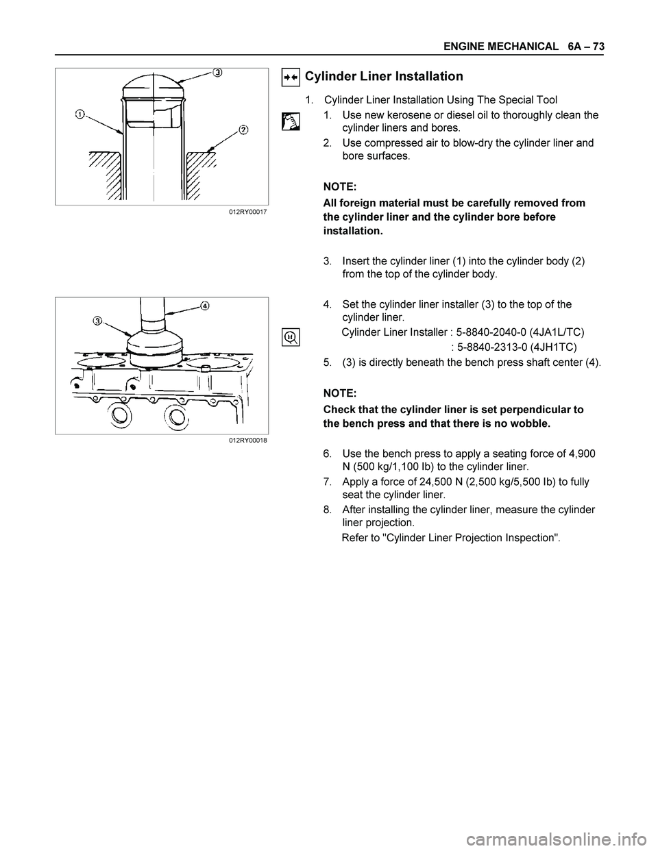
Cylinder Liner Installation
1. Cylinder Liner Installation Using The Special Tool
1. Use new kerosene or diesel oil to thoroughly clean the
cylinder liners and bores.
2. Use compressed air to blow-dry the cylinder liner and
bore surfaces.
NOTE:
All foreign material must be carefully removed from
the cylinder liner and the cylinder bore before
installation.
3. Insert the cylinder liner (1) into the cylinder body (2)
from the top of the cylinder body.
4. Set the cylinder liner installer (3) to the top of the
cylinder liner.
Cylinder Liner Installer : 5-8840-2040-0 (4JA1L/TC)
: 5-8840-2313-0 (4JH1TC)
5. (3) is directly beneath the bench press shaft center (4).
NOTE:
Check that the cylinder liner is set perpendicular to
the bench press and that there is no wobble.
6. Use the bench press to apply a seating force of 4,900
N (500 kg/1,100 Ib) to the cylinder liner.
7. Apply a force of 24,500 N (2,500 kg/5,500 Ib) to fully
seat the cylinder liner.
8. After installing the cylinder liner, measure the cylinder
liner projection.
Refer to "Cylinder Liner Projection Inspection".
012RY00017
012RY00018
Page 1214 of 4264
6A – 74 ENGINE MECHANICAL
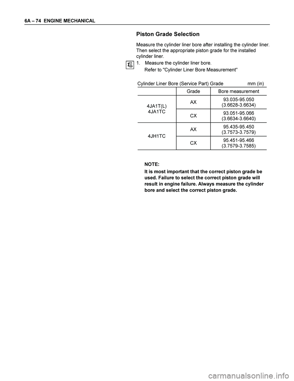
Piston Grade Selection
Measure the cylinder liner bore after installing the cylinder liner.
Then select the appropriate piston grade for the installed
cylinder liner.
1. Measure the cylinder liner bore.
Refer to "Cylinder Liner Bore Measurement"
Cylinder Liner Bore (Service Part) Grade mm (in)
Grade Bore measurement
AX 93.035-95.050
(3.6628-3.6634) 4JA1T(L)
4JA1TC
CX 93.051-95.066
(3.6634-3.6640)
AX 95.435-95.450
(3.7573-3.7579)
4JH1TC
CX 95.451-95.466
(3.7579-3.7585)
NOTE:
It is most important that the correct piston grade be
used. Failure to select the correct piston grade will
result in engine failure. Always measure the cylinder
bore and select the correct piston grade.
Page 1215 of 4264
ENGINE MECHANICAL 6A – 75
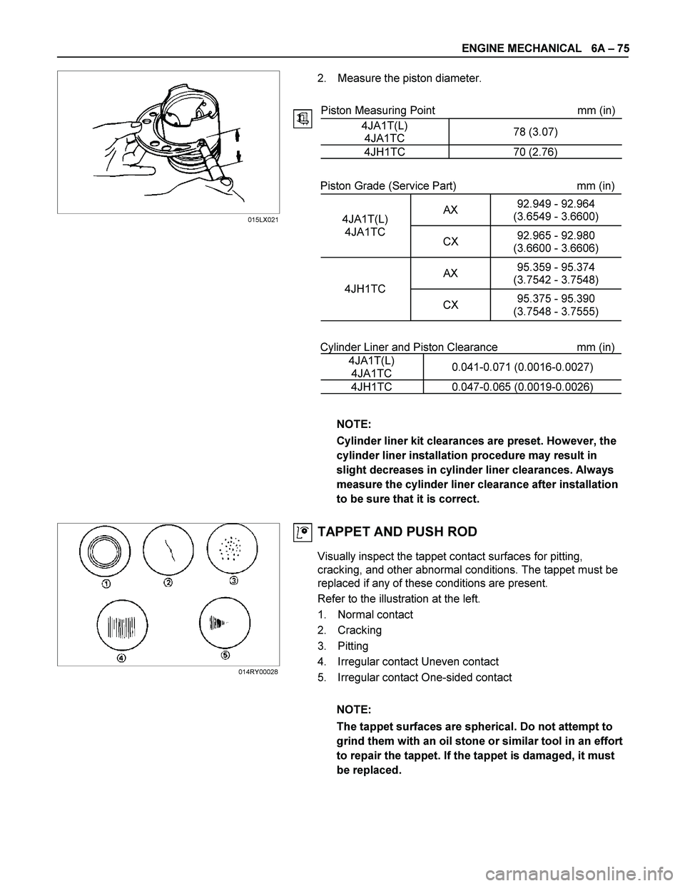
2. Measure the piston diameter.
Piston Measuring Point mm (in)
4JA1T(L)
4JA1TC 78 (3.07)
4JH1TC 70 (2.76)
Piston Grade (Service Part) mm (in)
AX 92.949 - 92.964
(3.6549 - 3.6600)
4JA1T(L)
4JA1TC
CX 92.965 - 92.980
(3.6600 - 3.6606)
AX 95.359 - 95.374
(3.7542 - 3.7548)
4JH1TC
CX 95.375 - 95.390
(3.7548 - 3.7555)
Cylinder Liner and Piston Clearance mm (in)
4JA1T(L)
4JA1TC 0.041-0.071 (0.0016-0.0027)
4JH1TC 0.047-0.065 (0.0019-0.0026)
NOTE:
Cylinder liner kit clearances are preset. However, the
cylinder liner installation procedure may result in
slight decreases in cylinder liner clearances. Always
measure the cylinder liner clearance after installation
to be sure that it is correct.
TAPPET AND PUSH ROD
Visually inspect the tappet contact surfaces for pitting,
cracking, and other abnormal conditions. The tappet must be
replaced if any of these conditions are present.
Refer to the illustration at the left.
1. Normal contact
2. Cracking
3. Pitting
4. Irregular contact Uneven contact
5. Irregular contact One-sided contact
NOTE:
The tappet surfaces are spherical. Do not attempt to
grind them with an oil stone or similar tool in an effort
to repair the tappet. If the tappet is damaged, it must
be replaced.
015LX021
014RY00028
Page 1216 of 4264

6A – 76 ENGINE MECHANICAL
Tappet Outside Diameter
Measure the tappet outside diameter with a micrometer.
If the measured value is less than the specified limit, the tappet
must be replaced.
Tappet Outside Diameter mm (in)
Standard Limit
12.97 - 12.99
(0.510 - 0.511) 12.95 (0.510)
Tappet and Cylinder Body Clearance mm (in)
Standard Limit
0.01 - 0.046
(0.0004 - 0.0018) 0.10 (0.004)
Push Rod Curvature
1. Lay the push rod on a surface plate.
2. Roll the push rod along the surface plate and measure the
push rod curvature with a thickness gauge.
If the measured value exceeds the specified limit, the push
rod must be replaced.
Pushrod Curvature mm (in)
Limit
0.3 (0.012)
3. Visually inspect both ends of the push rod for excessive
wear and damage. The push rod must be replaced if these
conditions are discovered during inspection.
014RY00029
012LX014
014RY00031
Page 1217 of 4264
ENGINE MECHANICAL 6A – 77
CAMSHAFT
Visually inspect the journals, the cams, the oil pump drive gear,
and the camshaft bearings for excessive wear and damage.
The camshaft and the camshaft bearings must be replaced if
these conditions are discovered during inspection.
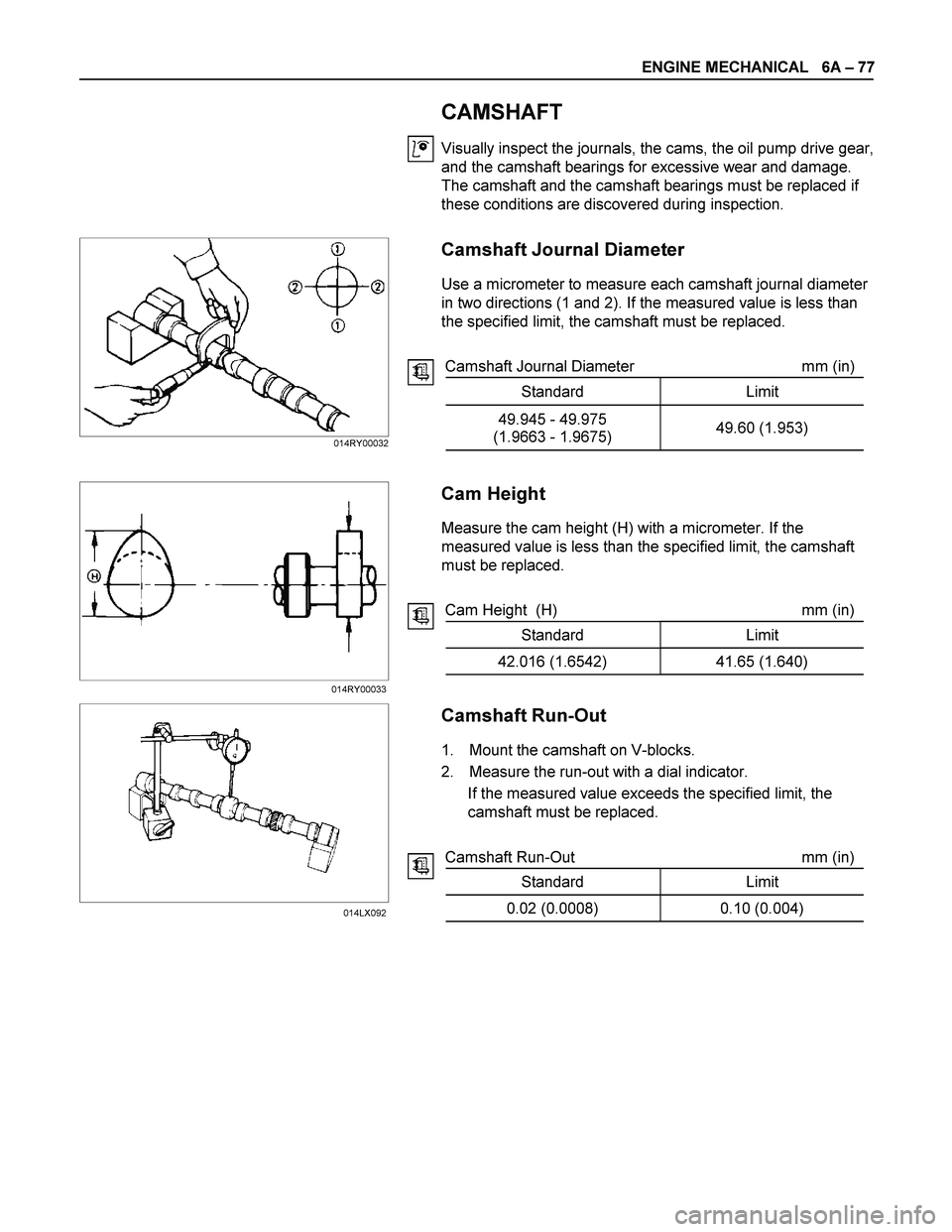
Camshaft Journal Diameter
Use a micrometer to measure each camshaft journal diameter
in two directions (1 and 2). If the measured value is less than
the specified limit, the camshaft must be replaced.
Camshaft Journal Diameter mm (in)
Standard Limit
49.945 - 49.975
(1.9663 - 1.9675) 49.60 (1.953)
Cam Height
Measure the cam height (H) with a micrometer. If the
measured value is less than the specified limit, the camshaft
must be replaced.
Cam Height (H) mm (in)
Standard Limit
42.016 (1.6542) 41.65 (1.640)
Camshaft Run-Out
1. Mount the camshaft on V-blocks.
2. Measure the run-out with a dial indicator.
If the measured value exceeds the specified limit, the
camshaft must be replaced.
Camshaft Run-Out mm (in)
Standard Limit
0.02 (0.0008) 0.10 (0.004)
014RY00032
014RY00033
014LX092
Page 1218 of 4264
6A – 78 ENGINE MECHANICAL
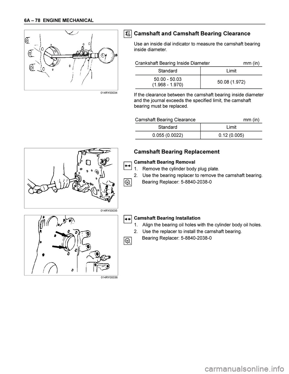
Camshaft and Camshaft Bearing Clearance
Use an inside dial indicator to measure the camshaft bearing
inside diameter.
Crankshaft Bearing Inside Diameter mm (in)
Standard Limit
50.00 - 50.03
(1.968 - 1.970) 50.08 (1.972)
If the clearance between the camshaft bearing inside diameter
and the journal exceeds the specified limit, the camshaft
bearing must be replaced.
Camshaft Bearing Clearance mm (in)
Standard Limit
0.055 (0.0022) 0.12 (0.005)
Camshaft Bearing Replacement
Camshaft Bearing Removal
1. Remove the cylinder body plug plate.
2. Use the bearing replacer to remove the camshaft bearing.
Bearing Replacer: 5-8840-2038-0
Camshaft Bearing Installation
1. Align the bearing oil holes with the cylinder body oil holes.
2. Use the replacer to install the camshaft bearing.
Bearing Replacer: 5-8840-2038-0
014RY00034
014RY00035
014RY00036
Page 1219 of 4264
ENGINE MECHANICAL 6A – 79
CRANKSHAFT AND BEARING
Inspect the surface of the crankshaft journals and crankpins for
excessive wear and damage.
Inspect the oil seal fitting surfaces for excessive wear and
damage.
Inspect the oil ports for obstructions.
NOTE:
To increase crankshaft strength, tufftriding (Nitrizing
Treatment) has been applied. Because of this, it is not
possible to regrind the crankshaft surfaces.
Therefore, under size bearing are not available.
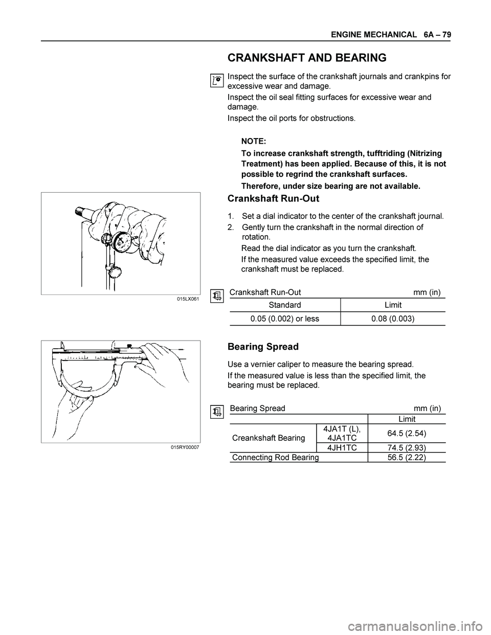
Crankshaft Run-Out
1. Set a dial indicator to the center of the crankshaft journal.
2. Gently turn the crankshaft in the normal direction of
rotation.
Read the dial indicator as you turn the crankshaft.
If the measured value exceeds the specified limit, the
crankshaft must be replaced.
Crankshaft Run-Out mm (in)
Standard Limit
0.05 (0.002) or less 0.08 (0.003)
Bearing Spread
Use a vernier caliper to measure the bearing spread.
If the measured value is less than the specified limit, the
bearing must be replaced.
Bearing Spread mm (in)
Limit
4JA1T (L),
4JA1TC 64.5 (2.54)
Creankshaft Bearing
4JH1TC 74.5 (2.93)
Connecting Rod Bearing 56.5 (2.22)
015LX061
015RY00007
Page 1220 of 4264

6A – 80 ENGINE MECHANICAL
Crankshaft Journal and Crankpin Diameter
1. Use a micrometer to measure the crankshaft journal
diameter across points 1 - 1 and 2 - 2.
2. Use the micrometer to measure the crankshaft journal
diameter at the two points (3 and 4).
3. Repeat Steps 1 and 2 to measure the crankpin diameter.
If the measured values are less than the specified limit, the
crankshaft must be replaced.
Crankshaft Journal and Diameter mm (in)
Standard Limit
4JA1T (L),
4JA1TC 59.921-59.928
(2.3591-2.3594) 59.91 (2.3586)
4JH1TC 69.917-69.932
(2.7526-2.7532) 69.91(2.7524)
Crankpin Diameter mm (in)
Standard Limit
52.915 - 52.930
(2.0833 - 2.0839) 52.90 (2.083)
Crankshaft Journal and Crankpin Uneven Wear mm (in)
Standard Limit
0.05 (0.002) or less 0.08 (0.003)
Crankshaft Journal and Crankpin Diameter
If the clearance between the measured bearing inside diameter
and the crankshaft journal diameter exceeds the specified limit,
the bearing and/or the crankshaft must be replaced.
Crankshaft Journal and Bearing Clearance mm (in)
Standard Limit
0.032 - 0.077
(0.0013 - 0.0030) 0.110 (0.0043)
015RY00008
015RY00009