piston ISUZU TF SERIES 2004 Workshop Manual
[x] Cancel search | Manufacturer: ISUZU, Model Year: 2004, Model line: TF SERIES, Model: ISUZU TF SERIES 2004Pages: 4264, PDF Size: 72.63 MB
Page 3852 of 4264
7A4–44 UNIT REPAIR (AW30–40LE)
Disassembly
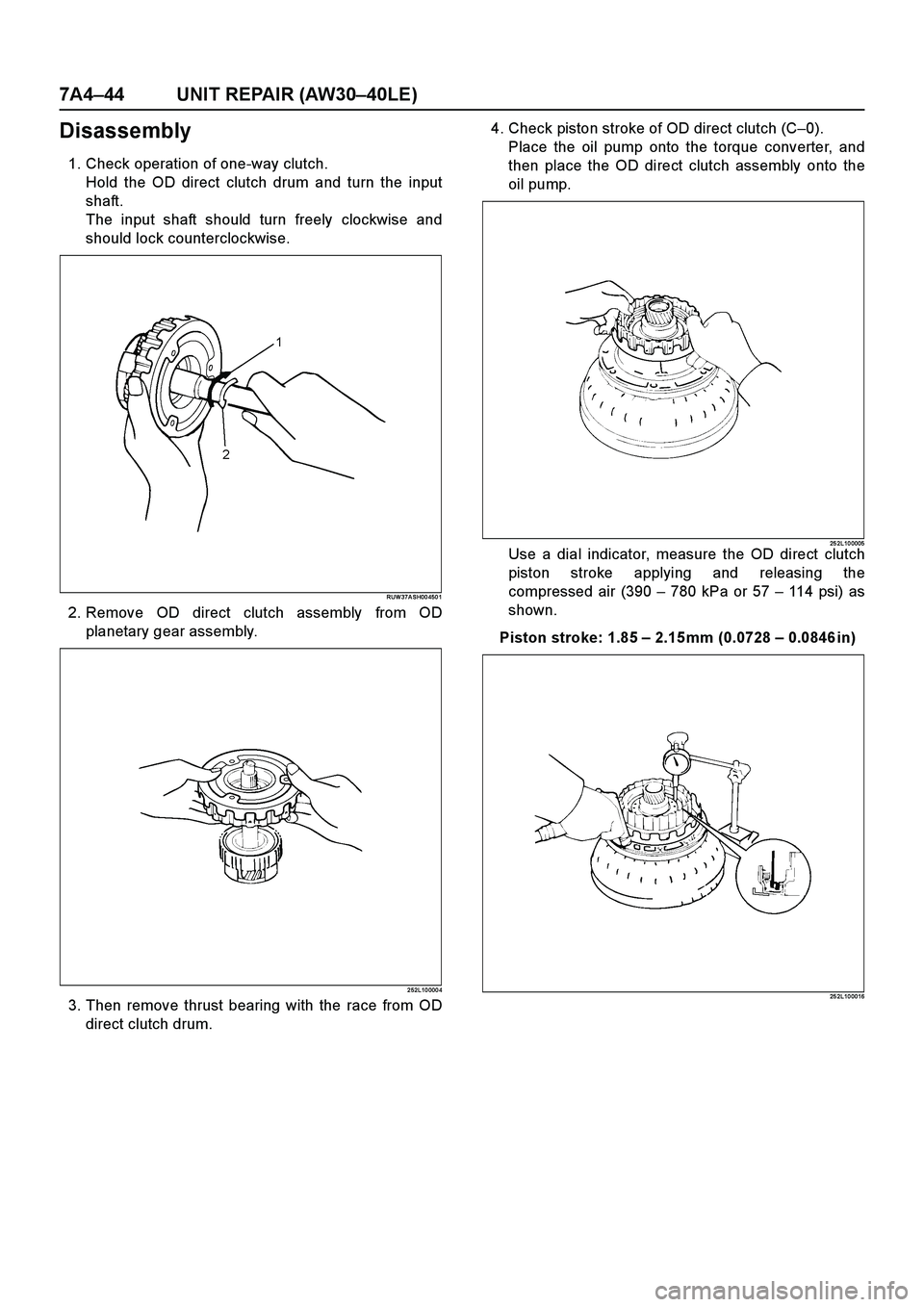
1. Check operation of one-way clutch.
Hold the OD direct clutch drum and turn the input
shaft.
The input shaft should turn freely clockwise and
should lock counterclockwise.
RUW 37A SH00 450 1
2. Remove OD direct clutch assembly from OD
planetary gear assembly.
2 52L10 000 4
3. Then remove thrust bearing with the race from OD
direct clutch drum.4. Check piston stroke of OD direct clutch (C–0).
Place the oil pump onto the torque converter, and
then place the OD direct clutch assembly onto the
oil pump.
25 2L10 0005Use a dial indicator, measure the OD direct clutch
piston stroke applying and releasing the
compressed air (390 – 780 kPa or 57 – 114 psi) as
shown.
Piston stroke: 1.85 – 2.15 mm (0.0728 – 0.0846 in)
25 2L10 0016
Page 3853 of 4264
UNIT REPAIR (AW30–40LE) 7A4–45
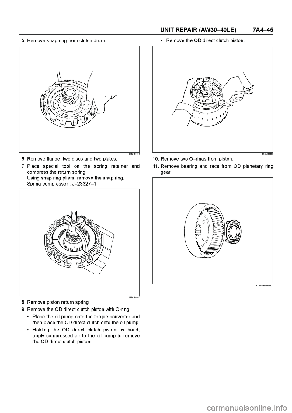
5. Remove snap ring from clutch drum.
2 52L10 000 6
6. Remove flange, two discs and two plates.
7. Place special tool on the spring retainer and
compress the return spring.
Using snap ring pliers, remove the snap ring.
Spring compressor : J–23327–1
2 52L10 000 7
8. Remove piston return spring
9. Remove the OD direct clutch piston with O-ring.
Place the oil pump onto the torque converter and
then place the OD direct clutch onto the oil pump.
Holding the OD direct clutch piston by hand,
apply compressed air to the oil pump to remove
the OD direct clutch piston.Remove the OD direct clutch piston.
25 2L10 0008
10. Remove two O–rings from piston.
11. Remove bearing and race from OD planetary ring
gear.
RTW4 6BSH00 0301
Page 3855 of 4264

UNIT REPAIR (AW30–40LE) 7A4–47
18. Remove the thrust washer.
Inspection and Repair
1. Check discs.
Using a micrometer, measure the thickness of the
discs.
Minimum thickness: 2.04 mm (0.0803 in)
If the thickness is less than the minimum, replace
the disc.
25 2RY 0 002 7
2. Check piston return spring
Using calipers, measure the free length of the return
spring.
Standard length: 15.8 mm (0.622 in)
25 2RY 0 002 8
3. Check OD direct clutch piston.
Check that the check ball is free by shaking the
piston. Check that the valve does not leak by
applying low-pressure compressed air.
25 2RY 0 0029
4. Check OD direct clutch drum bushings.
Using a dial indicator, measure the inside diameter
of the OD direct clutch drum bushings.
Maximum inside diameter: 27.11 mm (1.0673 in)
If the inside diameter is greater than the maximum,
replace the OD direct clutch drum.
25 2L10 0009
Page 3858 of 4264
7A4–50 UNIT REPAIR (AW30–40LE)
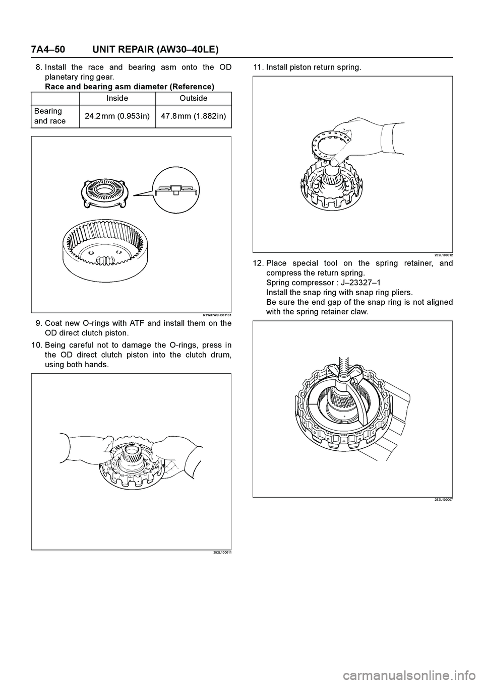
8. Install the race and bearing asm onto the OD
planetary ring gear.
Race and bearing asm diameter (Reference)
RTW3 7A SH00 110 1
9. Coat new O-rings with ATF and install them on the
OD direct clutch piston.
10. Being careful not to damage the O-rings, press in
the OD direct clutch piston into the clutch drum,
using both hands.
25 2L10 0011
11. Install piston return spring.
25 2L10 0012
12. Place special tool on the spring retainer, and
compress the return spring.
Spring compressor : J–23327–1
Install the snap ring with snap ring pliers.
Be sure the end gap of the snap ring is not aligned
with the spring retainer claw.
25 2L10 0007
Inside Outside
Bearing
and race24.2 mm (0.953 in) 47.8 mm (1.882 in)
Page 3859 of 4264

UNIT REPAIR (AW30–40LE) 7A4–51
13. Install two plates and two discs then install the
flange, with the flat side facing downward.
2 52L10 001 3
14. Install snap ring.
2 52L10 001 4
15. Check piston stroke of OD direct clutch (C–0)
Place the oil pump onto the torque converter, and
then place the OD direct clutch assembly onto the
oil pump.
25 2L10 0005Using a dial indicator, measure the OD direct clutch
piston stroke by applying and releasing the
compressed air (390 – 780 kPa or 57 – 114 psi) as
shown.
Piston stroke: 1.85 – 2.15 mm (0.0729 – 0.0847 in)
If the piston stroke is not within specification,
replace the disc and recheck the piston stroke.
If the piston stroke is nonstandard, select another
flange.
Flange sizes
25 2L10 0016
Flange thickness Flange thickness
3.8 mm (0.150 in) 3.4 mm (0.134 in)
3.7 mm (0.146 in) 3.3 mm (0.130 in)
3.6 mm (0.142 in) 3.2 mm (0.126 in)
3.5 mm (0.138 in) 3.1 mm (0.122 in)
Page 3861 of 4264

UNIT REPAIR (AW30–40LE) 7A4–53
OD Support Assembly
Disassembled View
2 52R20 0003
E nd O FCallo ut
Disassembly
1. Check OD brake piston movement.
Place the OD support assembly onto the direct
clutch assembly.
25 2RY 0 0042
Legend
(1) Thrust bearing
(2) Race
(3) Thrust washer (plastic)
(4) Snap ring(5) Piston return spring
(6) OD brake piston
(7) O-ring
(8) Oil seal ring
(9) OD support
Page 3862 of 4264

7A4–54 UNIT REPAIR (AW30–40LE)
Apply compressed air into the oil passage as
shown, and be sure that the OD brake piston moves
smoothly.
25 2RY 0 004 3
2. Remove the thrust bearing.
3. Remove the race.
4. Remove the thrust washer (plastic).
5. Place special tool on the spring retainer, and
compress the return spring with a shop press.
Spring compressor : J–37233
Remove the snap ring with a screwdriver.
RUW 37A SH00 310 1
6. Romove the piston return spring.7. Place the OD support onto the direct clutch
assembly.
Hold the OD brake piston so it is not slanted and
apply compressed air into the passage to remove
the OD brake piston.
Remove the OD brake piston.
25 2RY 0 0045
8. Remove the O-ring and oil seal rings from OD
support.
Inspection and Repair
Make necessary correction or parts replacement if wear,
damage or any abnormal conditions are found through
inspection.
1. Check piston return spring
Using calipers, measure the free length of the return
spring.
Standard length: 17.2 mm (0.677 in)
25 2RY 0 0046
Page 3863 of 4264

UNIT REPAIR (AW30–40LE) 7A4–55
Reassembly
1. Coat the two oil seal rings with ATF.
Contract the oil seals as shown, and install them
onto the OD support.
NOTE: Do not spread the ring ends more than
necessary.
25 2RY 0 004 7
2. Coat two new O-rings with ATF and install them on
the OD brake piston.
3. Being careful not to damage the O-rings, press the
brake piston into the OD support, using both hands.
25 2RY 0 004 8
4. Install piston return spring.
25 2RY 0 0049
5. Place special tool on the spring retainer, and
compress the return spring with a shop press.
Spring compressor : J–37233
Install the snap ring with a screwdriver.
Be sure the end gap of the snap ring is not aligned
with cutout portion of the OD support.
RUW3 7A SH00 3201
Page 3864 of 4264
7A4–56 UNIT REPAIR (AW30–40LE)
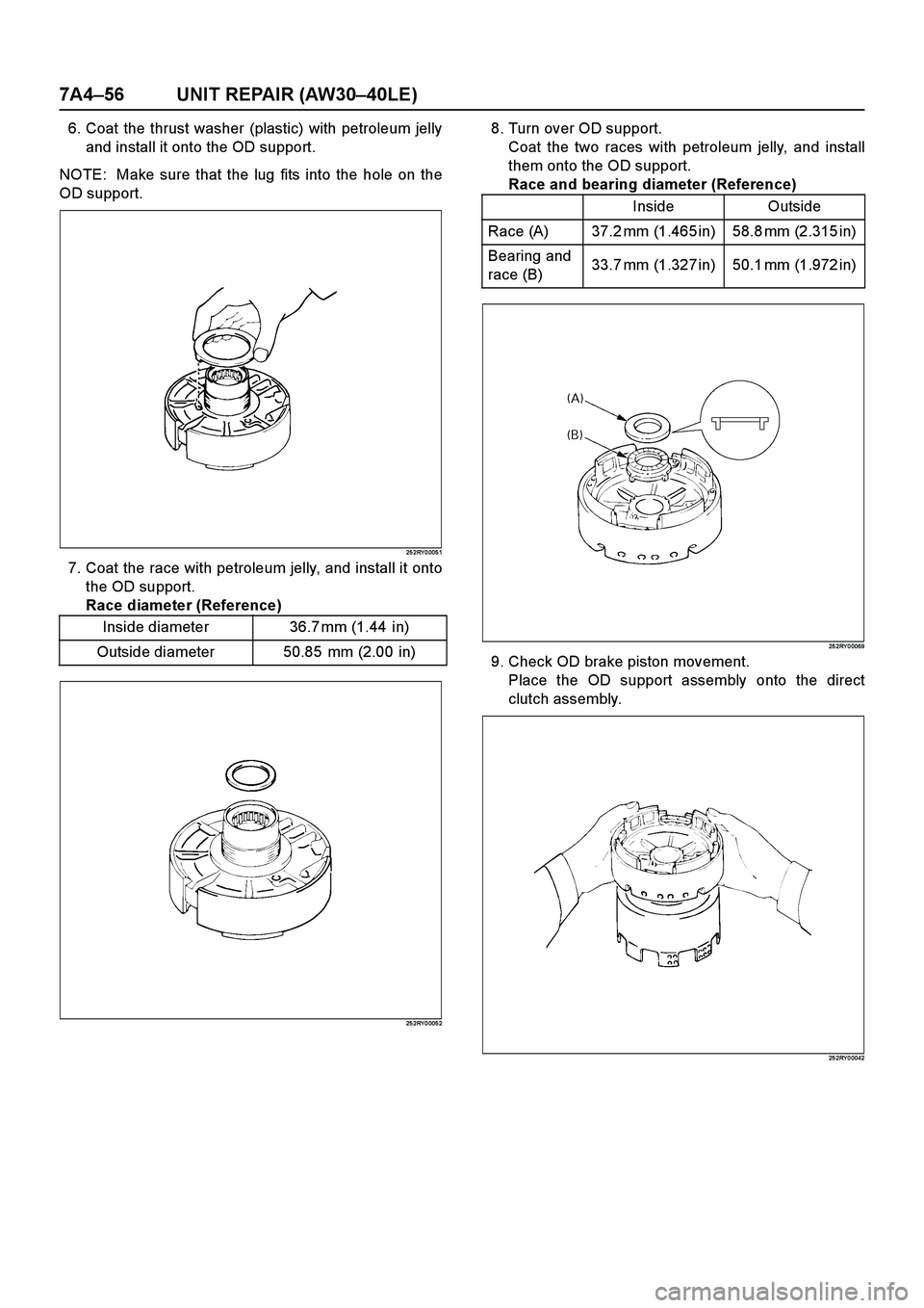
6. Coat the thrust washer (plastic) with petroleum jelly
and install it onto the OD support.
NOTE: Make sure that the lug fits into the hole on the
OD support.
25 2RY 0 005 1
7. Coat the race with petroleum jelly, and install it onto
the OD support.
Race diameter (Reference)
25 2RY 0 005 2
8. Turn over OD support.
Coat the two races with petroleum jelly, and install
them onto the OD support.
Race and bearing diameter (Reference)
25 2RY 0 0069
9. Check OD brake piston movement.
Place the OD support assembly onto the direct
clutch assembly.
25 2RY 0 0042
Inside diameter 36.7 mm (1.44 in)
Outside diameter 50.85 mm (2.00 in)
Inside Outside
Race (A) 37.2 mm (1.465 in) 58.8 mm (2.315 in)
Bearing and
race (B)33.7 mm (1.327 in) 50.1 mm (1.972 in)
Page 3865 of 4264

UNIT REPAIR (AW30–40LE) 7A4–57
Apply compressed air into the oil passage as
shown, and be sure that the OD brake piston moves
smoothly.
25 2RY 0 004 3