change time ISUZU TF SERIES 2004 Workshop Manual
[x] Cancel search | Manufacturer: ISUZU, Model Year: 2004, Model line: TF SERIES, Model: ISUZU TF SERIES 2004Pages: 4264, PDF Size: 72.63 MB
Page 28 of 4264
9A-8 SUPPLEMENTAL RESTRAINT SYSTEM
The SRS control unit is connected to the SRS wiring
harness by a 52–pin connector. This harness
connector uses a shorting clip across certain terminals
in the contact area. This shorting clip connects the
“AIR BAG” warning lamp to ground when the SRS
control unit harness connector is disconnected or CPA
(Connector Position Assurance) is not inserted even if
completely connected. This will cause the “AIR BAG”
warning lamp to come “ON” steady whenever the
ignition switch is at the ON or START positions with
the SRS control unit disconnected.
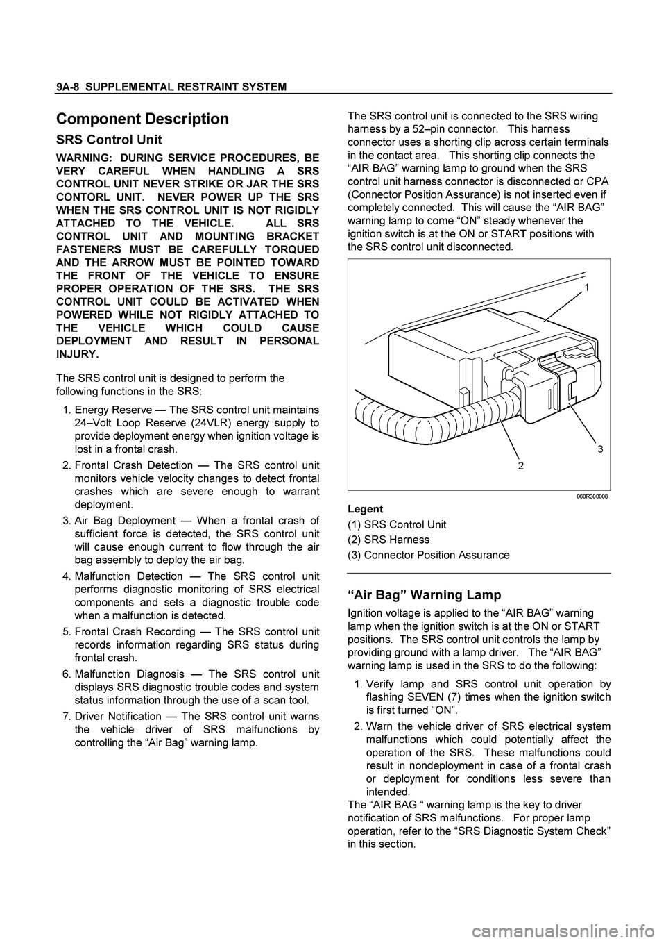
060R300008
Legent
(1) SRS Control Unit
(2) SRS Harness
(3) Connector Position Assurance
Component Description
SRS Control Unit
WARNING: DURING SERVICE PROCEDURES, BE
VERY CAREFUL WHEN HANDLING A SRS
CONTROL UNIT NEVER STRIKE OR JAR THE SRS
CONTORL UNIT. NEVER POWER UP THE SRS
WHEN THE SRS CONTROL UNIT IS NOT RIGIDLY
ATTACHED TO THE VEHICLE. ALL SRS
CONTROL UNIT AND MOUNTING BRACKET
FASTENERS MUST BE CAREFULLY TORQUED
AND THE ARROW MUST BE POINTED TOWARD
THE FRONT OF THE VEHICLE TO ENSURE
PROPER OPERATION OF THE SRS. THE SRS
CONTROL UNIT COULD BE ACTIVATED WHEN
POWERED WHILE NOT RIGIDLY ATTACHED TO
THE VEHICLE WHICH COULD CAUSE
DEPLOYMENT AND RESULT IN PERSONAL
INJURY.
The SRS control unit is designed to perform the
following functions in the SRS:
1. Energy Reserve — The SRS control unit maintains
24–
Volt Loop Reserve (24VLR) energy supply to
provide deployment energy when ignition voltage is
lost in a frontal crash.
2. Frontal Crash Detection — The SRS control uni
t
monitors vehicle velocity changes to detect frontal
crashes which are severe enough to warran
t
deployment.
3. Air Bag Deployment — When a frontal crash o
f
sufficient force is detected, the SRS control unit
will cause enough current to flow through the air
bag assembly to deploy the air bag.
4. Malfunction Detection —The SRS control uni
t
performs diagnostic monitoring of SRS electrical
components and sets a diagnostic trouble code
when a malfunction is detected.
5. Frontal Crash Recording — The SRS control uni
t
records information regarding SRS status during
frontal crash.
6. Malfunction Diagnosis —The SRS control uni
t
displays SRS diagnostic trouble codes and system
status information through the use of a scan tool.
7. Driver Notification — The SRS control unit warns
the vehicle driver of SRS malfunctions b
y
controlling the “Air Bag” warning lamp.
“Air Bag” Warning Lamp
Ignition voltage is applied to the “AIR BAG” warning
lamp when the ignition switch is at the ON or START
positions. The SRS control unit controls the lamp by
providing ground with a lamp driver. The “AIR BAG”
warning lamp is used in the SRS to do the following:
1.
Verify lamp and SRS control unit operation by
flashing SEVEN (7) times when the ignition switch
is first turned “ON”.
2. Warn the vehicle driver of SRS electrical system
malfunctions which could potentially affect the
operation of the SRS. These malfunctions could
result in nondeployment in case of a frontal crash
or deployment for conditions less severe than
intended.
The “AIR BAG “ warning lamp is the key to driver
notification of SRS malfunctions. For proper lamp
operation, refer to the “SRS Diagnostic System Check”
in this section.
Page 145 of 4264
PROPELLER SHAFT 4A-9
Phasing
The propeller shaft is designer and built with the yoke lugs
(ears) in line with each other. This design produces the
smoothest running shaft possible, called phasing. Vibration can
be caused by an out-of-phase propeller shaft. The propeller
shaft down each time the universal joint goes around. This
vibration would be the same as a person snapping rope and
watching the “wave” reaction flow to the end. A propeller shaft
working in phase would be similar to two persons snapping a
rope at the same time, and watching the “waves” meet and
cancel each other out. In comparison, this would be the same
as the universal joints on a propeller shaft. A total cancellation
of vibration produces a smooth flow of power in the driveline. It
is very important to apply a reference mark to the propeller
shaft before removal, to assure installation alignment.
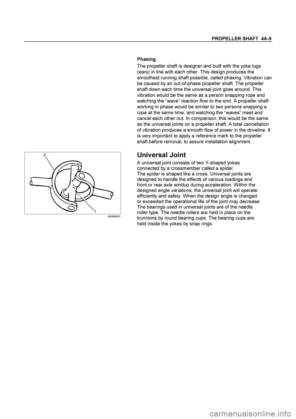
401RW015
Universal Joint
A universal joint consists of two Y-shaped yokes
connected by a crossmember called a spider.
The spider is shaped like a cross. Universal joints are
designed to handle the effects of various loadings and
front or rear axle windup during acceleration. Within the
designed angle variations, the universal joint will operate
efficiently and safely. When the design angle is changed
or exceeded the operational life of the joint may decrease.
The bearings used in universal joints are of the needle
roller type. The needle rollers are held in place on the
trunnions by round bearing cups. The bearing cups are
held inside the yokes by snap rings.
Page 336 of 4264
5A-20 BRAKE CONTROL SYSTEM
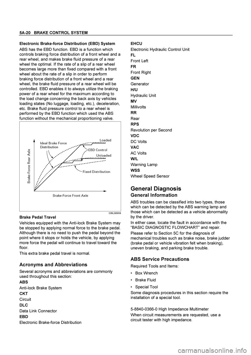
Electronic Brake-force Distribution (EBD) System
ABS has the EBD function. EBD is a function which
controls braking force distribution of a front wheel and a
rear wheel, and makes brake fluid pressure of a rear
wheel the optimal. If the rate of a slip of a rear wheel
becomes large more than fixed compared with a front
wheel about the rate of a slip in order to perform
braking force distribution of a front wheel and a rear
wheel, the brake fluid pressure of a rear wheel will be
controlled. EBD enables it to always utilize the braking
power of a rear wheel for the maximum according to
the load change concerning the back axis by vehicles
loading states (No luggage, loading, etc.), deceleration,
etc. Brake fluid pressure control to a rear wheel is
performed by the EBD function which used the ABS
function without the mechanical proportioning valve.
C05L300016
Brake Pedal Travel
Vehicles equipped with the Anti-lock Brake System may
be stopped by applying normal force to the brake pedal.
Although there is no need to push the pedal beyond the
point where it stops or holds the vehicle, by applying
more force the pedal will continue to travel toward the
floor.
This extra brake pedal travel is normal.
Acronyms and Abbreviations
Several acronyms and abbreviations are commonly
used throughout this section:
ABS
Anti-lock Brake System
CKT
Circuit
DLC
Data Link Connector
EBD
Electronic Brake-force Distribution
EHCU
Electronic Hydraulic Control Unit
FL
Front Left
FR
Front Right
GEN
Generator
H/U
Hydraulic Unit
MV
Millivolts
RR
Rear
RPS
Revolution per Second
VDC
DC Volts
VAC
AC Volts
W/L
Warning Lamp
WSS
Wheel Speed Sensor
General Diagnosis
General Information
ABS troubles can be classified into two types, those
which can be detected by the ABS warning lamp and
those which can be detected as a vehicle abnormality
by the driver.
In either case, locate the fault in accordance with the
“BASIC DIAGNOSTIC FLOWCHART” and repair.
Please refer to Section 5C for the diagnosis of
mechanical troubles such as brake noise, brake judder
(brake pedal or vehicle vibration felt when braking),
uneven braking, and parking brake trouble.
ABS Service Precautions
Required Tools and Items:
Box Wrench
Brake Fluid
Special Tool
Some diagnosis procedures in this section require the
installation of a special tool.
5-8840-0366-0 High Impedance Multimeter
When circuit measurements are requested, use a
circuit tester with high impedance.
Page 929 of 4264
ELECTRICAL-BODY AND CHASSIS 8A-271
Tachometer Off-Vehicle Inspection
Remove the tachometer from the meter assembly and
measure the resistance value and the current consumption
between each terminal.
SELF DIAGNOSTIC FUNCTION
Check that the speedometer, tachometer, fuel gauge, and
temperature gauge operate properly.
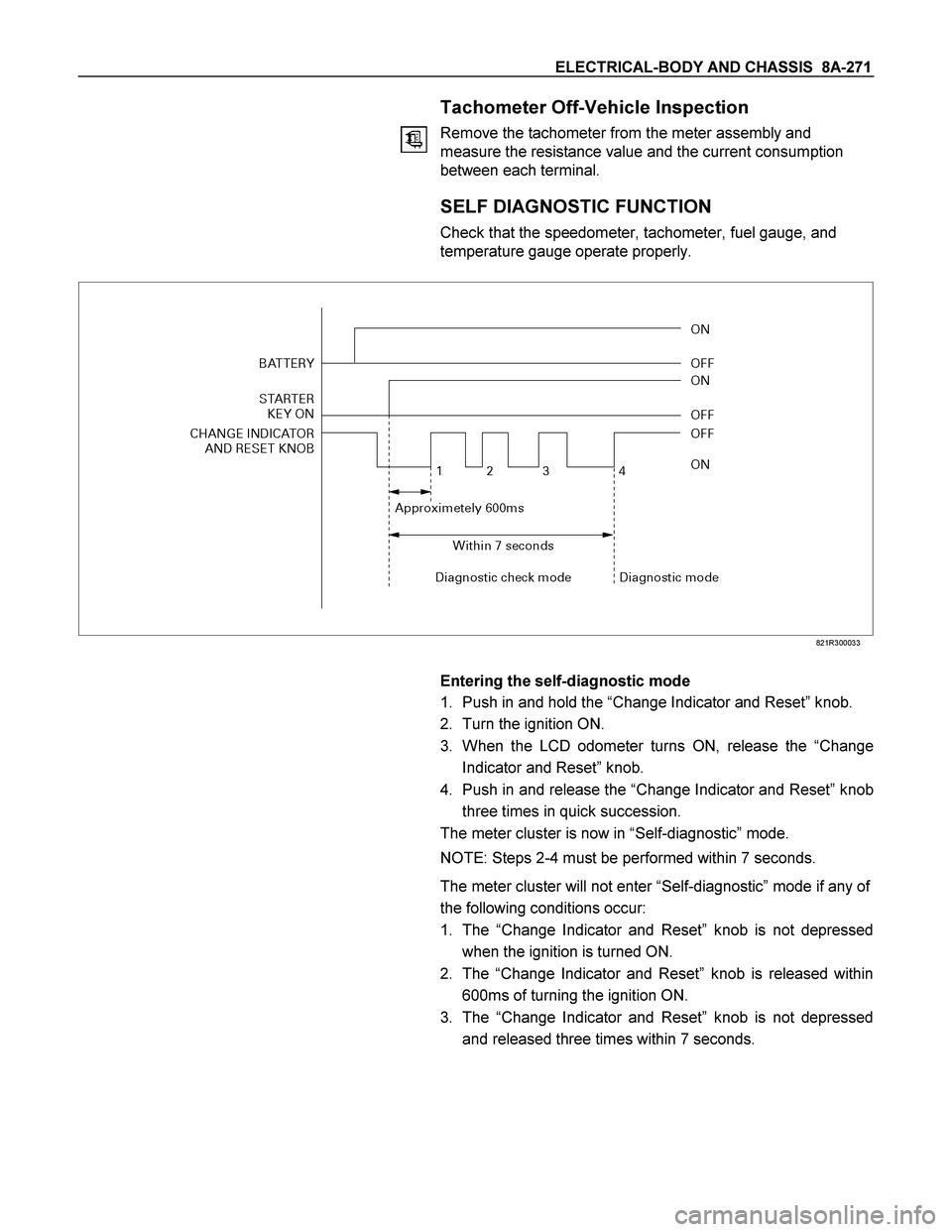
821R300033
Entering the self-diagnostic mode
1. Push in and hold the “Change Indicator and Reset” knob.
2. Turn the ignition ON.
3. When the LCD odometer turns ON, release the “Change
Indicator and Reset” knob.
4. Push in and release the “Change Indicator and Reset”knob
three times in quick succession.
The meter cluster is now in “Self-diagnostic” mode.
NOTE: Steps 2-4 must be performed within 7 seconds.
The meter cluster will not enter “Self-diagnostic”mode if any of
the following conditions occur:
1. The “Change Indicator and Reset” knob is not depressed
when the ignition is turned ON.
2. The “Change Indicator and Reset” knob is released within
600ms of turning the ignition ON.
3. The “Change Indicator and Reset” knob is not depressed
and released three times within 7 seconds.
Page 1307 of 4264
FUEL SYSTEM 6C – 7
INJECTION PUMP
RTW46CLF000201
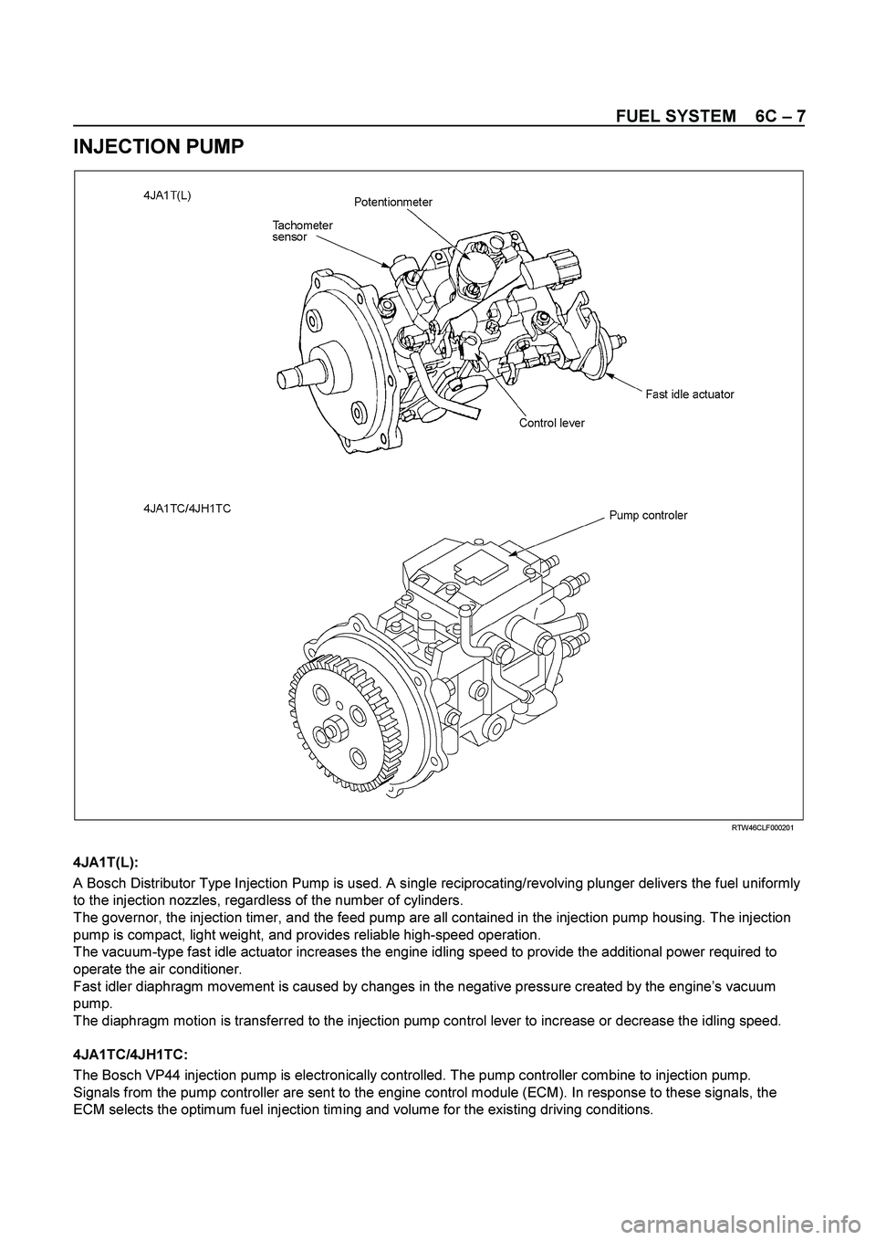
4JA1T(L):
A Bosch Distributor Type Injection Pump is used. A single reciprocating/revolving plunger delivers the fuel uniformly
to the injection nozzles, regardless of the number of cylinders.
The governor, the injection timer, and the feed pump are all contained in the injection pump housing. The injection
pump is compact, light weight, and provides reliable high-speed operation.
The vacuum-type fast idle actuator increases the engine idling speed to provide the additional power required to
operate the air conditioner.
Fast idler diaphragm movement is caused by changes in the negative pressure created by the engine’s vacuum
pump.
The diaphragm motion is transferred to the injection pump control lever to increase or decrease the idling speed.
4JA1TC/4JH1TC:
The Bosch VP44 injection pump is electronically controlled. The pump controller combine to injection pump.
Signals from the pump controller are sent to the engine control module (ECM). In response to these signals, the
ECM selects the optimum fuel injection timing and volume for the existing driving conditions.
Page 1441 of 4264
4JA1/4JH1 ENGINE DRIVEABILITY AND EMISSIONS 6E–69
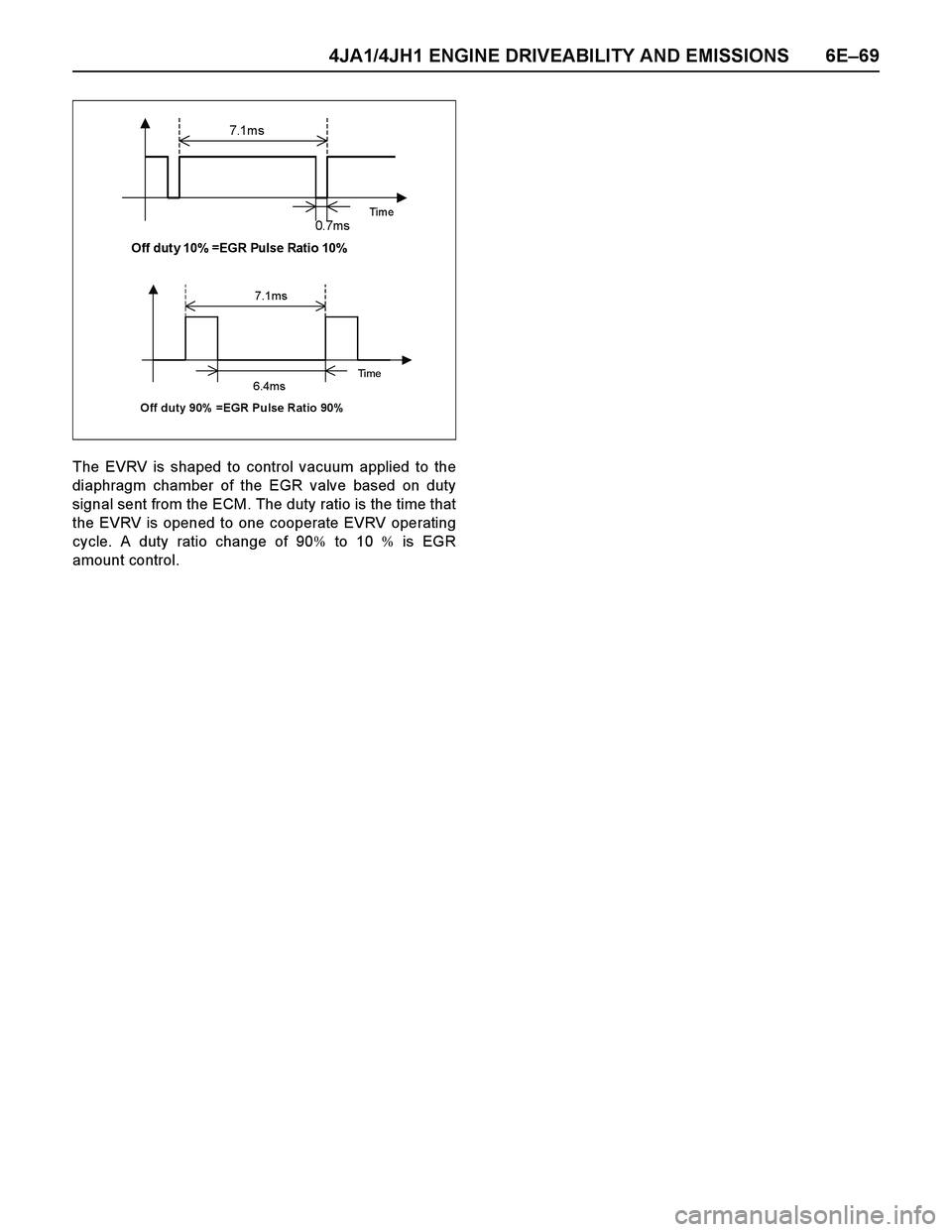
The EVRV is shaped to control vacuum applied to the
diaphragm chamber of the EGR valve based on duty
signal sent from the ECM. The duty ratio is the time that
the EVRV is opened to one cooperate EVRV operating
cycle. A duty ratio change of 90% to 10 % is EGR
amount control.
7.1m s
Time 0. 7m s Off duty 10% =EGR Pulse Ratio 10%
7.1ms
Ti m e 6.4ms Off duty 90% =EGR Pulse Ratio 90%
Page 1447 of 4264
4JA1/4JH1 ENGINE DRIVEABILITY AND EMISSIONS 6E–75
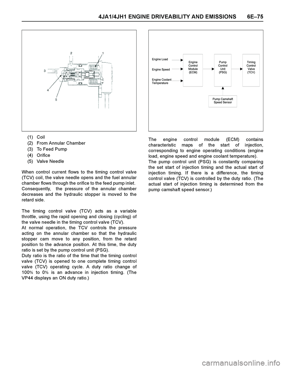
When control current flows to the timing control valve
(TCV) coil, the valve needle opens and the fuel annular
chamber flows through the orifice to the feed pump inlet.
Consequently, the pressure of the annular chamber
decreases and the hydraulic stopper is moved to the
retard side.
The timing control valve (TCV) acts as a variable
throttle, using the rapid opening and closing (cycling) of
the valve needle in the timing control valve (TCV).
At normal operation, the TCV controls the pressure
acting on the annular chamber so that the hydraulic
stopper cam move to any position, from the retard
position to the advance position. At this time, the duty
ratio is set by the pump control unit (PSG).
Duty ratio is the ratio of the time that the timing control
valve (TCV) is opened to one complete timing control
valve (TCV) operating cycle. A duty ratio change of
100% to 0% is an advance in injection timing. (The
VP44 displays an ON duty ratio.)The engine control module (ECM) contains
characteristic maps of the start of injection,
corresponding to engine operating conditions (engine
load, engine speed and engine coolant temperature).
The pump control unit (PSG) is constantly comparing
the set start of injection timing and the actual start of
injection timing. If there is a difference, the timing
control valve (TCV) is controlled by the duty ratio. (The
actual start of injection timing is determined from the
pump camshaft speed sensor.) (1) Coil
(2) From Annular Chamber
(3) To Feed Pump
(4) Orifice
(5) Valve Needle
Engine Load
Engine Speed
Engine Coolant
TemperatureEngine
Control
Module
(ECM)Pump
Control
Unit
(PSG)
Pump Camshaft
Speed Sensor
Timing
Control
Valve
(TCV)
Page 1454 of 4264
6E–82 4JA1/4JH1 ENGINE DRIVEABILITY AND EMISSIONS
GENERAL SERVICE INFORMATION
Serviceability Issues
Non-OEM Parts
All of the OBD diagnostics have been calibrated to run
with OEM parts. Accordingly, if commercially sold
sensor or switch is installed, it makes a wrong diagnosis
and turns on the check engine lamp.
Aftermarket electronics, such as cellular phones,
stereos, and anti-theft devices, may radiate EMI into the
control system if they are improperly installed. This may
cause a false sensor reading and turn on the check
engine lamp.
Poor Vehicle Maintenance
The sensitivity of OBD diagnostics will cause the check
engine lamp to turn on if the vehicle is not maintained
properly. Restricted oil filters, fuel filters, and crankcase
deposits due to lack of oil changes or improper oil
viscosity can trigger actual vehicle faults that were not
previously monitored prior to OBD. Poor vehicle
maintenance can not be classified as a “non-vehicle
fault”, but with the sensitivity of OBD diagnostics,
vehicle maintenance schedules must be more closely
followed.
Related System Faults
Many of the OBD system diagnostics will not run if the
ECM detects a fault on a related system or component.
Visual/Physical Engine Compartment
Inspection
Perform a careful visual and physical engine
compartment inspection when performing any
diagnostic procedure or diagnosing the cause of an
emission test failure. This can often lead to repairing a
problem without further steps. Use the following
guidelines when performing a visual/physical
inspection:
Inspect all vacuum hoses for punches, cuts,
disconnects, and correct routing.
Inspect hoses that are difficult to see behind other
components.
Inspect all wires in the engine compartment for
proper connections, burned or chafed spots, pinched
wires, contact with sharp edges or contact with hot
exhaust manifolds or pipes.
Basic Knowledge of Tools Required
NOTE: Lack of basic knowledge of this powertrain
when performing diagnostic procedures could result in
an incorrect diagnosis or damage to powertrain
components. Do not attempt to diagnose a powertrain
problem without this basic knowledge.
A basic understanding of hand tools is necessary to
effectively use this section of the Service Manual.
ON-BOARD DIAGNOSTIC (OBD)
On-Board Diagnostic (Self Diagnosis
System) Tests
A diagnostic test is a series of steps, the result of which
is a pass or fail reported to the diagnostic ex ecutive.
When a diagnostic test reports a pass result, the
diagnostic ex ecutive records the following data:
The diagnostic test has been completed since the
last ignition cycle.
The diagnostic test has passed during the current
ignition cycle.
The fault identified by the diagnostic test is not
currently active.
When a diagnostic test reports a fail result, the
diagnostic ex ecutive records the following data:
The diagnostic test has been completed since the
last ignition cycle.
The fault identified by the diagnostic test is currently
active.
The fault has been active during this ignition cycle.
The operating conditions at the time of the failure.
The Diagnostic Executive
The Diagnostic Executive is a unique segment of
software which is designed to coordinate and prioritize
the diagnostic procedures as well as define the protocol
for recording and displaying their results. The main
responsibilities of the Diagnostic Ex ecutive are listed as
follow s:
Commanding the check engine lamp on and off
DTC logging and clearing
Current status information on each diagnostic
Diagnostic Information
The diagnostic charts and functional checks are
designed to locate a faulty circuit or component through
a process of logical decisions. The charts are prepared
with the requirement that the vehicle functioned
correctly at the time of assembly and that there are not
multiple faults present.
There is a continuous self-diagnosis on certain control
functions. This diagnostic capability is complemented
by the diagnostic procedures contained in this manual.
The language of communicating the source of the
malfunction is a system of diagnostic trouble codes.
When a malfunction is detected by the control module, a
diagnostic trouble code is set and the check engine
lamp is illuminated.
Check Engine Lamp
The check engine lamp looks the same as the check
engine lamp you are already familiar with, the “Check
Engine” lamp.
Basically, the check engine lamp is turned on when the
Page 1464 of 4264
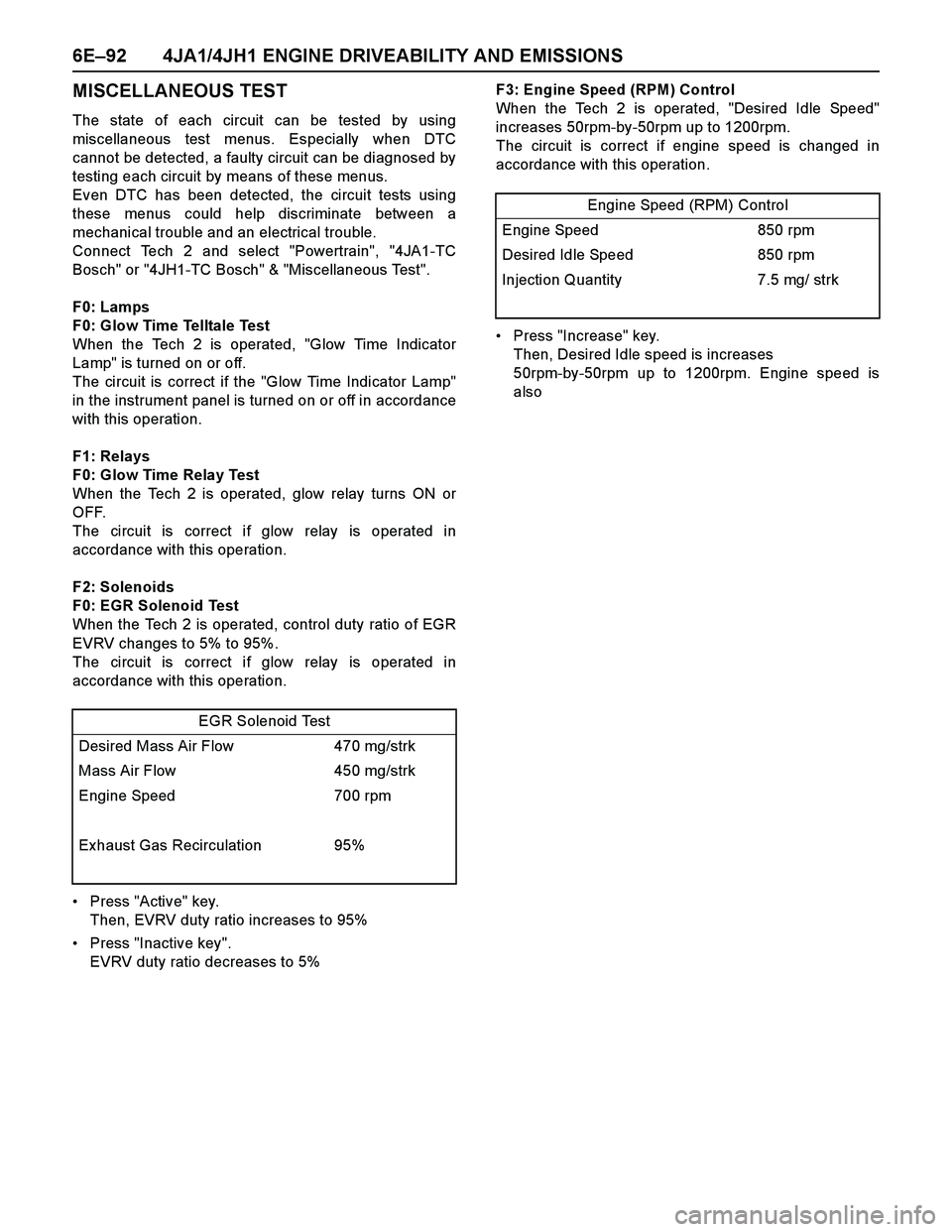
6E–92 4JA1/4JH1 ENGINE DRIVEABILITY AND EMISSIONS
MISCELLANEOUS TEST
The state of each circuit can be tested by using
miscellaneous test menus. Especially when DTC
cannot be detected, a faulty circuit can be diagnosed by
testing each circuit by means of these menus.
Even DTC has been detected, the circuit tests using
these menus could help discriminate between a
mechanical trouble and an electrical trouble.
Connect Tech 2 and select "Powertrain", "4JA1-TC
Bosch" or "4JH1-TC Bosch" & "Miscellaneous Test".
F0: Lamps
F0: Glow Time Telltale Test
When the Tech 2 is operated, "Glow Time Indicator
Lamp" is turned on or off.
The circuit is correct if the "Glow Time Indicator Lamp"
in the instrument panel is turned on or off in accordance
with this operation.
F1: Relays
F0: Glow Time Relay Test
When the Tech 2 is operated, glow relay turns ON or
OFF.
The circuit is correct if glow relay is operated in
accordance with this operation.
F2: Solenoids
F0: EGR Solenoid Test
When the Tech 2 is operated, control duty ratio of EGR
EVRV changes to 5% to 95%.
The circuit is correct if glow relay is operated in
accordance with this operation.
Press "Active" key.
Then, EVRV duty ratio increases to 95%
Press "Inactive key".
EVRV duty ratio decreases to 5%F3: Engine Speed (RPM) Control
When the Tech 2 is operated, "Desired Idle Speed"
increases 50rpm-by-50rpm up to 1200rpm.
The circuit is correct if engine speed is changed in
accordance with this operation.
Press "Increase" key.
Then, Desired Idle speed is increases
50rpm-by-50rpm up to 1200rpm. Engine speed is
also
EGR Solenoid Test
Desired Mass Air Flow 470 mg/strk
Mass Air Flow 450 mg/strk
Engine Speed 700 rpm
Exhaust Gas Recirculation 95%
Engine Speed (RPM) Control
Engine Speed 850 rpm
Desired Idle Speed 850 rpm
Injection Quantity 7.5 mg/ strk
Page 1469 of 4264
![ISUZU TF SERIES 2004 Workshop Manual 4JA1/4JH1 ENGINE DRIVEABILITY AND EMISSIONS 6E–97
After recording the snapshot in Tech2, transfer the data
from Tech2 to PC by the below procedures.
1. Start TIS2000.
2. Select [Snapshot Upload] on ISUZU TF SERIES 2004 Workshop Manual 4JA1/4JH1 ENGINE DRIVEABILITY AND EMISSIONS 6E–97
After recording the snapshot in Tech2, transfer the data
from Tech2 to PC by the below procedures.
1. Start TIS2000.
2. Select [Snapshot Upload] on](/img/61/57180/w960_57180-1468.png)
4JA1/4JH1 ENGINE DRIVEABILITY AND EMISSIONS 6E–97
After recording the snapshot in Tech2, transfer the data
from Tech2 to PC by the below procedures.
1. Start TIS2000.
2. Select [Snapshot Upload] on the TIS2000 start
screen.
3. Select [Upload from trouble diagnosis tool (transfer
from diagnosis tester)] or click the corresponding
icon of the tool bar.
4. Select Tech2, and transfer the recorded snapshot
information.
5. Select the transferred snapshot.
6. After ending transfer of the snapshot, data
parameter list is displayed on the screen.3. Snapshot data is displayed with TIS2000
[Snapshot Upload] function.
Snapshot is stored in the PC hard disk or floppy disk,
and can be displayed any time.
Stored snapshot can be displayed by the below
procedures.
1. Start TIS2000.
2. Select [Snapshot Upload] on the TIS2000 start
screen.
3. Select [Open the existing files] or click the
corresponding icon of the tool bar.
4. Select the transferred snapshot.
5. Open the snapshot, to display the data parameter
list on the screen.
Graph display Values and graphs (Max. 3 graphs):
1. Click the icon for graph display. [Graph Parameter]
window opens.
2. Click the first graph icon of the window upper part,
and select one parameter from the list of the window
lower part. Selected parameter is displayed nest to
the graph icon. Graph division can be selected in
the field on the parameter right side.
3. Repeat the same procedures with the 2nd and 3rd
icons.
4. After selecting all parameters to be displayed (Max .
3 parameters), click [OK] button.
5. Parameter selected is displayed in graph form on
the right of the data parameter on the screen.
6. Graph display can be moved with the navigation
icon.
7. For displaying another parameter by graph, click the
parameter of the list, drug the mouse to the display
screen while pressing the mouse button and release
the mouse button. New parameter is displayed at
the position of the previous parameter. For
displaying the graph display screen in full size,
move the cursor upward on the screen. When thecursor is changed to the magnifying glass form, click
the screen. Graph screen is displayed on the whole
screen.