ISUZU TF SERIES 2004 Workshop Manual
TF SERIES 2004
ISUZU
ISUZU
https://www.carmanualsonline.info/img/61/57180/w960_57180-0.png
ISUZU TF SERIES 2004 Workshop Manual
Page 818 of 4264
8A-160 ELECTRICAL-BODY AND CHASSIS
RTU4Z0SH000901
ILLUMINATION SWITCH
RTW48ASH000601
Inspection
Check to see if there is any continuity between the terminals of
the switch.
Replace the switch when the result of inspection is found
abnormal.
RTW48ASH000501
Removal
Preparation:
Disconnect the battery ground cable.
1. Instrument panel driver lower cover assembly
Refer to the removal steps Sec.10
2. Harness switch
3. Illumination control
To remove the switch, push the lock from the back side of
the cluster assembly.
4. Remove the bulb.
Page 819 of 4264
ELECTRICAL-BODY AND CHASSIS 8A-161
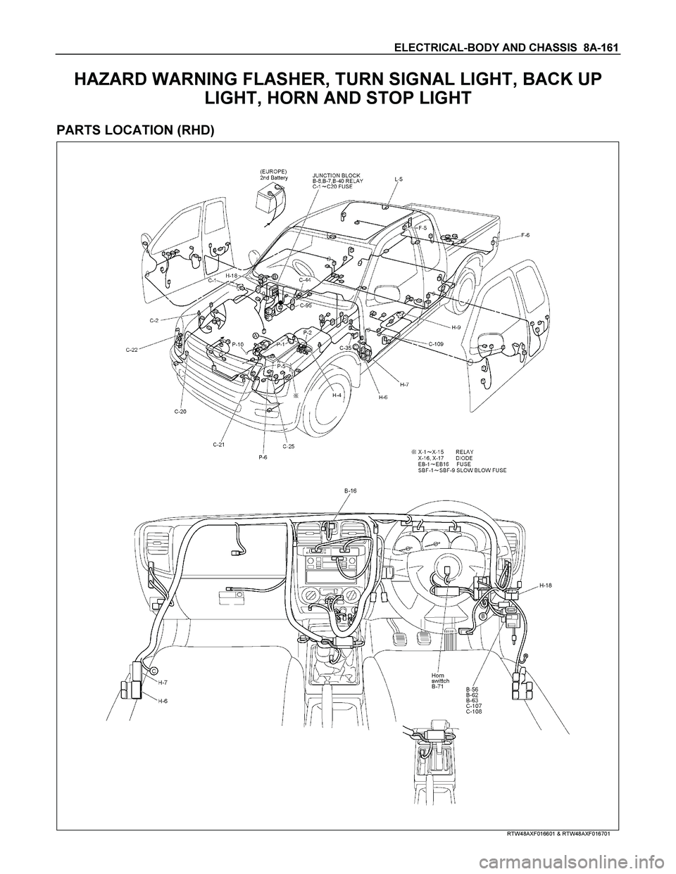
HAZARD WARNING FLASHER, TURN SIGNAL LIGHT, BACK UP
LIGHT, HORN AND STOP LIGHT
PARTS LOCATION (RHD)
RTW48AXF016601 & RTW48AXF016701
Page 820 of 4264
8A-162 ELECTRICAL-BODY AND CHASSIS
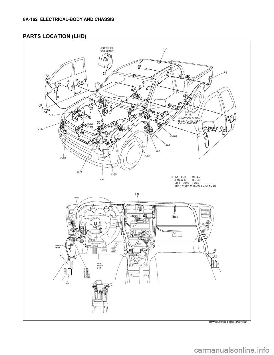
PARTS LOCATION (LHD)
RTW48AXF0168 & RTW48AXF16901
Page 821 of 4264
ELECTRICAL-BODY AND CHASSIS 8A-163
PARTS LOCATION
RTW38DXF007501
Page 822 of 4264
8A-164 ELECTRICAL-BODY AND CHASSIS
PARTS LOCATION
RTW48AXF013001
Page 823 of 4264
ELECTRICAL-BODY AND CHASSIS 8A-165
CIRCUIT DIAGRAM
RTW48AXF027801
Page 824 of 4264

8A-166 ELECTRICAL-BODY AND CHASSIS
TROUBLESHOOTING
STOPLIGHT AND HIGH MOUNTED STOPLIGHT
1. One side of stoplight does not light
Checkpoint Trouble Cause Countermeasure
Replace the bulb or repair
connector contact
Burned out bulb or poor
connector contact
NG
Repair open circuit or
connector contact
Repair open circuit or
connector contact
Open circuit or poor connector
contact
Continuity between
9
H-9 - 2 F-6 (LH) (or
2
F-5 (RH))
Open circuit or poor connector
contact
Continuity between
C-109 - 4 F-6 (LH) (or
4
F-5 (RH)) NG NG OK
OK
Stoplight bulb continuity
2. Both sides of stoplight do not light
Adjust the switch installation
position
Stop light switch (or brake
switch) function
Incorrect the switch installation
or adjustment
NG
Repair open circuit or
connector contact
Voltage between 2 F-6
ground or 2
F-5 - ground
with brake pedal depressed
(Should be battery voltage
present)
Open circuit or poor connector
contact between stoplight
switch (or brake switch) and
stoplight NG OK
Reinstall or replace fuse No.
SBF-9 (50A)
or 1
C-108 - 4
C-107
Fuse No. C-18 (15A)
Fuse No. SBF-9 (50A, Fuse
and Relay box)
or 1
C-108 - 4
C-107
Fuse No. C-18 (15A)
Poor fuse contact or blown
NG
OK
Page 825 of 4264
ELECTRICAL-BODY AND CHASSIS 8A-167
3. High mounted stoplight does not light
Checkpoint Trouble Cause Countermeasure
Repair or replace the high
mounted stoplight
Continuity between 3
L-5 -
1
L-5
High mounted stoplight
malfunction
NG
Repair an open circuit or
connector contact between
3
L-5 - 8 H-6
Voltage between 1 L-5 -
ground with brake pedal
depressed
(Should be battery voltage
present)
Open circuit or poor connector
contact
NG OK
Repair grounding point contact
C-2
Grounding point
C-2
Poor grounding point contact
NG
OK
Page 826 of 4264
8A-168 ELECTRICAL-BODY AND CHASSIS
TURN SIGNAL LIGHT AND HAZARD WARNING LIGHT
1. Turn signal light does not light on both sides (RH and LH)
Checkpoint Trouble Cause Countermeasure
Replace the flasher unit
Flasher unit malfunction
NG
Repair or replace the
combination switch
Turn signal switch continuity
between connector
5
B-60 - 6 B-60 and
5
B-60 - 7 B-60 when
turn signal switch operates
Short circuit between
connector 3
B-61 - 1 B-61
when turn signal switch
operates with starter switch
in “ON” position (Turn
signal light should be ON)
Poor switch point contact or
faulty switch
NG OK
Reinstall or replace fuse No.
EB-16 (10A)
Fuse No. EB-16 (10A, Fuse
box)
Poor fuse contact or blown
fuse
NG
OK OK
Repair open circuit or
connector contact
Continuity between
connector 2
B-61 -ground
(Should be continuity)
Open circuit or poor connector
contact
NG
Page 827 of 4264

ELECTRICAL-BODY AND CHASSIS 8A-169
2. Turn signal light does not light on one side (RH or LH)
Checkpoint Trouble Cause Countermeasure
Repair open circuit or
connector contact
Open circuit or poor connector
contact
NG
(LH)
Continuity between
3
C-25 - 6 B-60 (FRT),
1
C-35 - 6 B-60 (SIDE)
1
F-6 - 6 B-60 (RR)
(RH)
Continuity between
3
C-18 - 7 B-60 (FRT),
1
C-1 - 7 B-60 (SIDE)
1
F-5 - 7 B-60 (RR)
Repair or replace the
combination switch
Turn signal switch continuity
Poor switch point contact or
faulty switch
NG
OK OK
Repair open circuit or
connector contact
Open circuit or poor connector
contact
NG
3. Hazard warning light does not light
Repair or replace the hazard
SW.
Hazard SW. malfunction
NG
Voltage between 5 B-16 -
ground (Should be battery
voltage present)
Hazard SW. continuity
Reinstall or replace the fuse
No. EB-16 (10A)
Fuse No. EB-16 (10A, Relay
and fuse box)
Poor fuse contact or blown
fuse
NG
OK OK
Repair open circuit or
connector contact
Open circuit or poor
connector contact between
fuse No. EB-16 (10A) -
5
B-16 NG
4. Flashing rate too fast (One side)
Replace the bulb or repair
open circuitInspect bulbBurned out bulb NG