EXHAUST SYSTEM 6F – 17
INSPECTION AND REPAIR
Make the necessary adjustments, repairs, and part replacements if excessive wear or damage is discovered during
inspection.
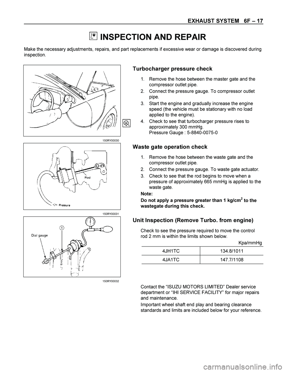
Turbocharger pressure check
1. Remove the hose between the master gate and the
compressor outlet pipe.
2. Connect the pressure gauge. To compressor outlet
pipe.
3. Start the engine and gradually increase the engine
speed (the vehicle must be stationary with no load
applied to the engine).
4. Check to see that turbocharger pressure rises to
approximately 300 mmHg.
Pressure Gauge : 5-8840-0075-0
150RY00030
Waste gate operation check
1. Remove the hose between the waste gate and the
compressor outlet pipe.
2. Connect the pressure gauge. To waste gate actuator.
3. Check to see that the rod begins to move when a
pressure of approximately 665 mmHg is applied to the
waste gate.
Note:
Do not apply a pressure greater than 1 kg/cm
2 to the
wastegate during this check.
150RY00031
Unit Inspection (Remove Turbo. from engine)
Check to see the pressure required to move the control
rod 2 mm is within the limits shown below.
Kpa/mmHg
4JH1TC 134.8/1011
4JA1TC 147.7/1108
150RY00032
Contact the “ISUZU MOTORS LIMITED” Dealer service
department or “IHI SERVICE FACILITY” for major repairs
and maintenance.
Important wheel shaft end play and bearing clearance
standards and limits are included below for your reference.
6F – 18 EXHAUST SYSTEM
Wheel Shaft End Play
Use a dial indicator to measure the wheel shaft end play.
Apply a force of 1.2 kg (2.6 lb/11.8N) alternately to the
compressor wheel end and the turbine wheel end.
Wheel Shaft End Play mm (in)
Standard Limit
0.03 - 0.06
(0.001 - 0.002) 0.09 (0.004)
150RY00034
Wheel Shaft and Bearing Clearance
Use a dial indicator to measure the wheel shaft and
bearing clearance.
Wheel Shaft and Bearing Clearance mm (in)
Standard Limit
0.056 - 0.127
(0.0022 - 0.0050) 0.127 (0.0050)
150RY00036
6F – 20 EXHAUST SYSTEM
IHI SERVICE NETWORK
For inquiries relating to turbochargers, please contact your ISUZU distributor or the nearest IHI Turbocharger
Service Facility.
HEADQUARTERS
ISHIKAWAJIMA HARIMA HEAVY INDUSTRIES CO., LTD.(IHI)
General Machinery Division
Tokyo Chuo Building 1-6-2 Marunouchi Chiyoda-ku
Tokyo 100-0005 JAPAN
TEL: 81-(3)-3286-2405 to 2407 (3 lines)
FAX: 81-(3)-3286-2430
CHINA
IHI BEIJING OFFICE
Room 705, China World Trade Center, No. 1 Jian Guo Men Wai Avenue
Beijing, People’s Republic of CHINA
TEL: 86-(1)-505-4997, 0408
FAX: 86-(1)-505-4350
TLX: 210343 IHIPK CN
TAIWAN
IHI TAIPEI OFFICE
Room 1202, Chia Hsin Building, No. 96 Chung Shan
North Road, Section 2, Taipei, TAIWAN
TEL: 886-(2)-542-5520, 5521, 5523
FAX: 886-(2)-542-4362
TLX: 11320 IHICO
THAILAND
IHI BANGKOK OFFICE
8th Floor, Thaniya Building, 62 Silom Road, Bangkok, THAILAND
TEL: 66-(2)-236-3490, 7356, 9099
FAX: 66-(2)-236-7340
TLX: 82375 IHICO TH
MALAYSIA
IHI KUALA LUMPUR OFFICE
Letter Box No. 52, 22nd Floor, UBN Tower,
10 Jin. P. Ramlee 50250 Kuala Lumpur, MALAYSIA
TEL: 60-(3)-232-1255, 1271
FAX: 60-(3)-232-1418
TLX: IHI KLMA 20257
INDONESIA
IHI JAKARTA OFFICE
9th Floor, Skyline Building JI. M. H. Thamrin, No. 9, Jakarta, INDONESIA
TEL: 62-(21)-32-2147, 390-2211
FAX: 62-(21)-32-3273
TLX: 44175 IHIJKT
ACCELERATOR CONTROL 6H – 1
SECTION 6H
ACCELERATOR CONTROL
TABLE OF CONTENTS
PAGE
Removal and Installation............................................................................................... 6H - 2
Removal...................................................................................................................... 6H - 6
Inspection................................................................................................................... 6H - 6
Installation.................................................................................................................. 6H - 6
6H – 6 ACCELERATOR CONTROL
RTW46HMH000201
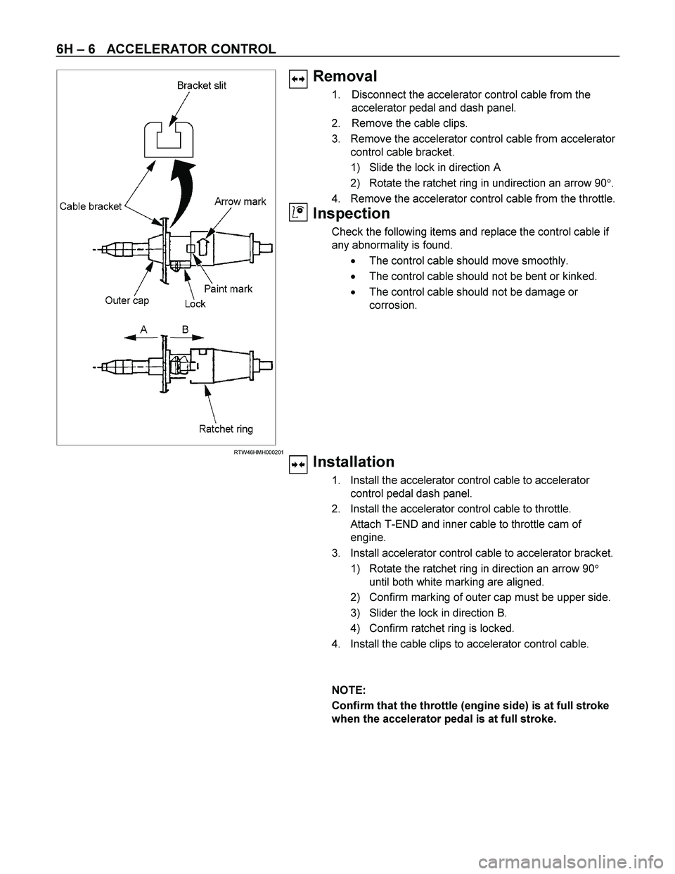
Removal
1. Disconnect the accelerator control cable from the
accelerator pedal and dash panel.
2. Remove the cable clips.
3. Remove the accelerator control cable from accelerator
control cable bracket.
1) Slide the lock in direction A
2) Rotate the ratchet ring in undirection an arrow 90�.
4. Remove the accelerator control cable from the throttle.
Inspection
Check the following items and replace the control cable if
any abnormality is found.
� The control cable should move smoothly.
� The control cable should not be bent or kinked.
� The control cable should not be damage or
corrosion.
Installation
1. Install the accelerator control cable to accelerator
control pedal dash panel.
2. Install the accelerator control cable to throttle.
Attach T-END and inner cable to throttle cam of
engine.
3. Install accelerator control cable to accelerator bracket.
1) Rotate the ratchet ring in direction an arrow 90�
until both white marking are aligned.
2) Confirm marking of outer cap must be upper side.
3) Slider the lock in direction B.
4) Confirm ratchet ring is locked.
4. Install the cable clips to accelerator control cable.
NOTE:
Confirm that the throttle (engine side) is at full stroke
when the accelerator pedal is at full stroke.


