fuel pump ISUZU TF SERIES 2004 Workshop Manual
[x] Cancel search | Manufacturer: ISUZU, Model Year: 2004, Model line: TF SERIES, Model: ISUZU TF SERIES 2004Pages: 4264, PDF Size: 72.63 MB
Page 2688 of 4264

6E–112 ENGINE DRIVEABILITY AND EMISSIONS
22 1. Command the fuel pump ON with the Scan Tool.
2. Using suitable pliers which will not damage the
fuel hose, gradually apply pressure with the pliers
to pinch the flex ible fuel return hose closed.376 kPa
(55 psi)
Does the fuel pressure indicated by the fuel pressure
gauge rise above the first specified value?
Caution: Do not let the fuel pressure exceed the
second specified value.414 kPa
(60 psi) Go to Step 11Go to Step 7
23 1. Command the fuel pump ON with the Scan Tool.
2. Remove the fuel filler cap and listen for the sound
of the fuel pump running.
3. Turn the pump off.
Was the fuel pump running?—Go to Step 7Go to Fuel
System
Electrical Test
Chart Step Action Value(s) Yes No
Page 2846 of 4264

6E–270 ENGINE DRIVEABILITY AND EMISSIONS
FUEL PRESSURE RELIEF
Caution: To reduce the risk of fire and personal
injury, it is necessary to relieve the fuel system
pressure before servicing the fuel system
components.
Caution: After relieving the fuel system pressure, a
small amount of fuel may be released when
servicing fuel lines or connections. Reduce the
chance of personal injury by covering the fuel line
fitting with a short towel before disconnecting the
fittings. The towel will absorb any fuel that may leak
out. When the disconnect is completed, place the
towel in an approved container.
1. Remove the fuel filler cap.
2. Remove the fuel pump relay from the underhood
relay box .
3. Start the engine and allow it to stall.
4. Crank the engine for about 30 seconds.
5. Disconnect the negative battery cable.
FUEL RAIL ASSEMBLY
Removal Procedure
NOTE:
Use care when removing the fuel rail assembly in
order to prevent damage to the injector al connector
terminal and the injector spray tips.
Fitting should be capped and holes plugged during
servicing to prevent dirt and other contaminants from
entering open lines and passage.
Important: An eight-digit identification number is
stamped on side of the fuel injector. Refer to this
number when you service the fuel rail or when a
replacement part is required.
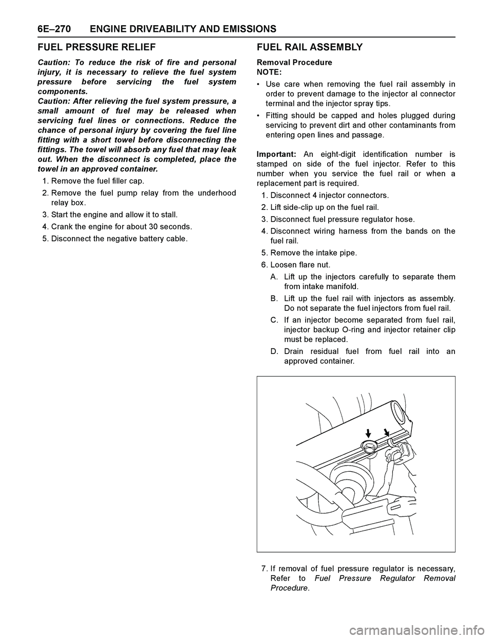
1. Disconnect 4 injector connectors.
2. Lift side-clip up on the fuel rail.
3. Disconnect fuel pressure regulator hose.
4. Disconnect wiring harness from the bands on the
fuel rail.
5. Remove the intake pipe.
6. Loosen flare nut.
A. Lift up the injectors carefully to separate them
from intake manifold.
B. Lift up the fuel rail with injectors as assembly.
Do not separate the fuel injectors from fuel rail.
C. If an injector become separated from fuel rail,
injector backup O-ring and injector retainer clip
must be replaced.
D. Drain residual fuel from fuel rail into an
approved container.
7. If removal of fuel pressure regulator is necessary,
Refer to Fuel Pressure Regulator Removal
Procedure.
Page 2849 of 4264

ENGINE DRIVEABILITY AND EMISSIONS 6E–273
7. Install fuel rail assembly. Tighten the nuts to 19 N·m
(1.9 kgf·m). Refer to Fuel Rail Installation
Procedure.
Tighten the flare nut to 27 - 33 N·m (2.8 - 3.4 kgf·m).
8. Connect the negative battery cable.FUEL PRESSURE REGULATOR
Removal Procedure
Caution: To reduce the risk of fire and personal
injury, it is necessary to relieve the fuel system
pressure before servicing the fuel system
components.
Caution: After relieving the fuel system pressure, a
small amount of fuel may be released when
servicing fuel lines or connections. Reduce the
chance of personal injury by covering the fuel line
fitting with a shop towel before disconnecting the
fittings. The towel will absorb any fuel that may leak
out. When the disconnect is completed, place the
towel in an approved container.
NOTE: Compressed air must never be used to test or
clean a fuel pressure regulator, as damage to the fuel
pressure regulator may occur.
NOTE: To prevent damage to the fuel pressure
regulator, do not immerse the pressure regulator in
solvent.
Removal Procedure
1. Depressurize the fuel system. Refer to Fuel
Pressure Relief Procedure.
2. Disconnect the negative battery cable.
3. Remove the fuel pump relay.
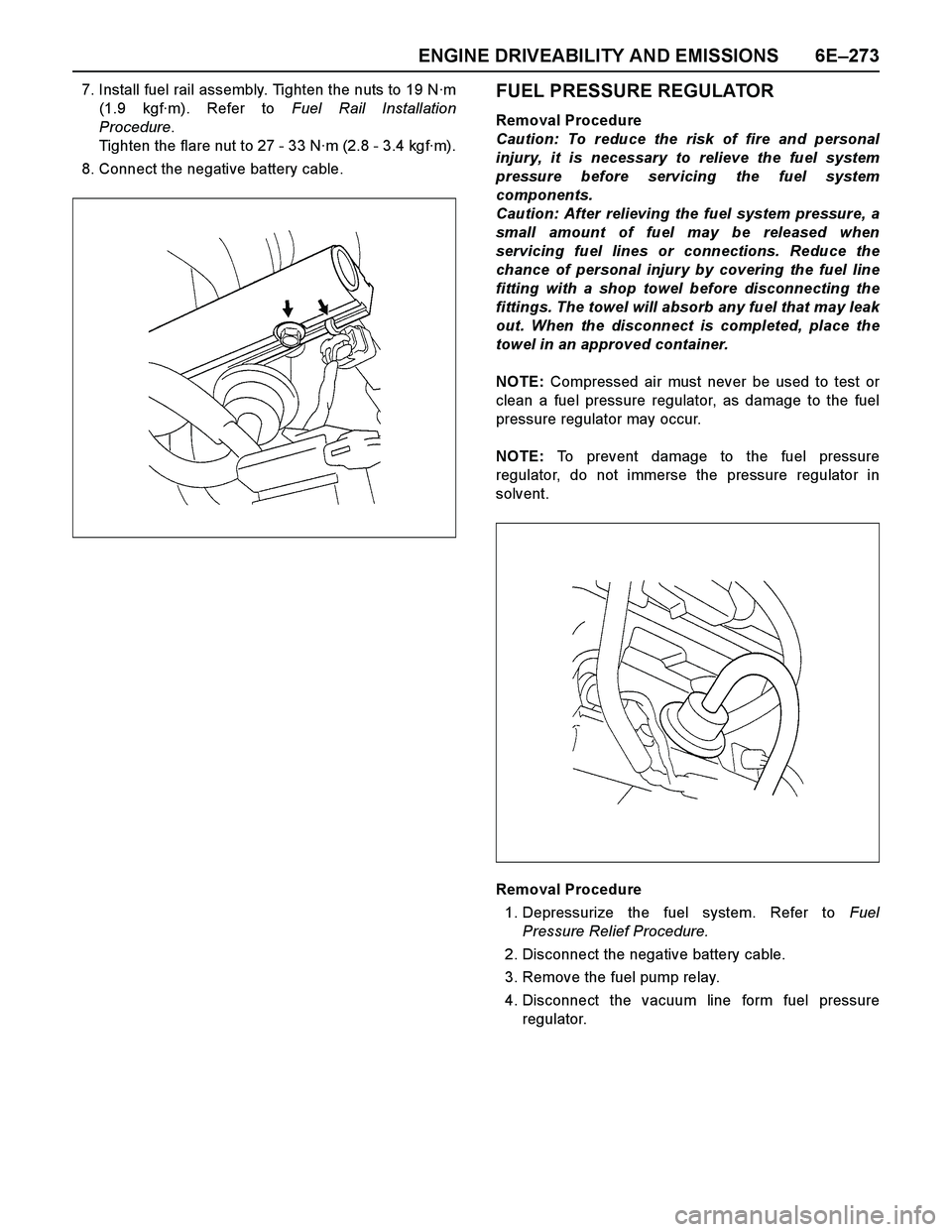
4. Disconnect the vacuum line form fuel pressure
regulator.
Page 2850 of 4264

6E–274 ENGINE DRIVEABILITY AND EMISSIONS
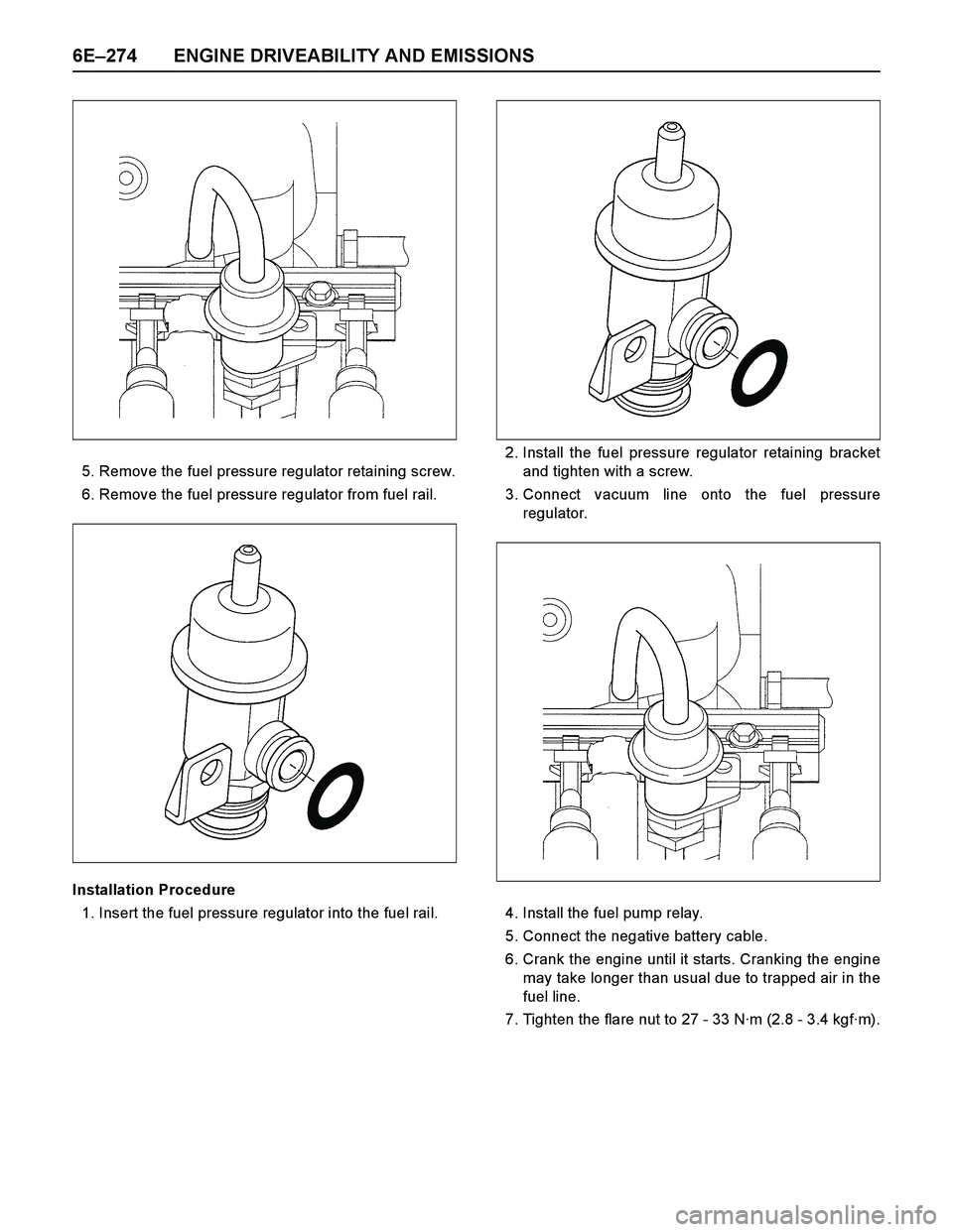
5. Remove the fuel pressure regulator retaining screw.
6. Remove the fuel pressure regulator from fuel rail.
Installation Procedure
1. Insert the fuel pressure regulator into the fuel rail.2. Install the fuel pressure regulator retaining bracket
and tighten with a screw.
3. Connect vacuum line onto the fuel pressure
regulator.
4. Install the fuel pump relay.
5. Connect the negative battery cable.
6. Crank the engine until it starts. Cranking the engine
may take longer than usual due to trapped air in the
fuel line.
7. Tighten the flare nut to 27 - 33 N·m (2.8 - 3.4 kgf·m).
Page 3299 of 4264

IMMOBILIZER SYSTEM 11A-13
Immobilizer control unit (ICU);
Mechanical Control Engine (4JA1-T)
Immobilizer control unit (ICU) permits engine starting,
when the security code which compares the securit
y
code registered into the transponder (key) and the
security code registered into ICU, and is similarl
y
registered into ICU and engine immobilizer unit (DDS-1)
is compared and it is judged that it is normal. When the
code registered into the key is unusual, and when not
recognizing a security code, engine immobilizer unit
does not permit starting of engine by the fuel cut valve
on the fuel pump.
The engine immobilizer unit is located with fuel cut
valve on fuel pump 4JA1-T engine.
The immobilizer control unit decides whether there is an
abnormality the security code based on the engine
immobilizer unit security code.
When the problem found, the engine immobilizer unit
stops fuel fupply by the fuel cut valve.
RAW4B0SF000101