Fuel sensor ISUZU TF SERIES 2004 User Guide
[x] Cancel search | Manufacturer: ISUZU, Model Year: 2004, Model line: TF SERIES, Model: ISUZU TF SERIES 2004Pages: 4264, PDF Size: 72.63 MB
Page 1375 of 4264

4JA1/4JH1 ENGINE DRIVEABILITY AND EMISSIONS 6E–3
(Symptom Code 2) (Flash Code 14) Engine
Coolant Temperature Sensor Circuit
LowInput .................................................. 6E-165
DIAGNOSTIC TROUBLE CODE (DTC) P0180
(SYMPTOM CODE B) (FLASH CODE 15)
FUEL TEMPERATURE SENSOR CIRCUIT
RANGE/PERFORMANCE ....................... 6E-168
Circuit Description ..................................... 6E-168
Diagnostic Aids .......................................... 6E-168
Diagnostic Trouble Code (DTC) P0180
(Symptom Code B) (Flash Code 15) Fuel
Temperature Sensor Circuit
Range/Performance ................................ 6E-169
DIAGNOSTIC TROUBLE CODE (DTC) P0215
(SYMPTOM CODE A) (FLASH CODE 52)
FUEL CUTOFF SOLENOID VALVE
MALFUNCTION ....................................... 6E-170
DIAGNOSTIC TROUBLE CODE (DTC) P0215
(SYMPTOM CODE B) (FLASH CODE 52)
FUEL CUTOFF SOLENOID VALVE
CIRCUIT HIGH INPUT ............................ 6E-170
DIAGNOSTIC TROUBLE CODE (DTC) P0215
(SYMPTOM CODE C) (FLASH CODE 52)
FUEL CUTOFF SOLENOID VALVE ALWAYS
ACTIVE .................................................... 6E-170
DIAGNOSTIC TROUBLE CODE (DTC) P0215
(SYMPTOM CODE D) (FLASH CODE 52)
FUEL CUTOFF SOLENOID VALVE
MALFUNCTION ....................................... 6E-170
Circuit Description ..................................... 6E-171
Diagnostic Aids .......................................... 6E-171
Diagnostic Trouble Code (DTC) P0215
(Symptom Code A) (Flash Code 52) Fuel
Cutoff Solenoid Valve Malfunction ........... 6E-171
Diagnostic Trouble Code (DTC) P0215
(Symptom Code B) (Flash Code 52) Fuel
Cutoff Solenoid Valve Circuit High Input . 6E-173
Diagnostic Trouble Code (DTC) P0215
(Symptom Code C) (Flash Code 52) Fuel
Cutoff Solenoid Valve Always Active ....... 6E-175
Diagnostic Trouble Code (DTC) P0215
(Symptom Code D) (Flash Code 52) Fuel
Cutoff Solenoid Valve Malfunction ........... 6E-177
DIAGNOSTIC TROUBLE CODE (DTC) P0216
(SYMPTOM CODE A) (FLASH CODE 54)
INJECTION TIMING CONTROL CIRCUIT
MALFUNCTION ....................................... 6E-178
DIAGNOSTIC TROUBLE CODE (DTC) P0216
(SYMPTOM CODE B) (FLASH CODE 54)
INJECTION TIMING CONTROL CIRCUIT
MALFUNCTION ....................................... 6E-178
Circuit Description ..................................... 6E-179
Diagnostic Aids .......................................... 6E-179Diagnostic Trouble Code (DTC) P0216
(Symptom Code A) (Flash Code 54) Injection
Timing Control Circuit Malfunction ........... 6E-180
Diagnostic Trouble Code (DTC) P0216
(Symptom Code B) (Flash Code 54) Injection
Timing Control Circuit Malfunction ........... 6E-180
DIAGNOSTIC TROUBLE CODE (DTC) P0243
(SYMPTOM CODE 3) (FLASH CODE 64)
TURBOCHARGER WASTEGATE
SOLENOID "A" RANGE/PERFORMANCE 6E-183
DIAGNOSTIC TROUBLE CODE (DTC) P0243
(SYMPTOM CODE 4) (FLASH CODE 64)
TURBOCHARGER WASTEGATE
SOLENOID"A" LOW ................................ 6E-183
DIAGNOSTIC TROUBLE CODE (DTC) P0243
(SYMPTOM CODE 4) (FLASH CODE 64)
TURBOCHARGER WASTEGATE
SOLENOID "A" LOW ............................... 6E-183
DIAGNOSTIC TROUBLE CODE (DTC) P0243
(SYMPTOM CODE 5) (FLASH CODE 64)
TURBOCHARGER WASTEGATE
SOLENOID "A" RANGE/PERFORMANCE 6E-183
DIAGNOSTIC TROUBLE CODE (DTC) P0243
(SYMPTOM CODE 6) (FLASH CODE 64)
TURBOCHARGER WASTEGATE
SOLENOID "A" MALFUNCTION ............. 6E-183
DIAGNOSTIC TROUBLE CODE (DTC) P0243
(SYMPTOM CODE 8) (FLASH CODE 64)
TURBOCHARGER WASTEGATE
SOLENOID"A" HIGH ............................... 6E-183
Circuit description ...................................... 6E-184
Diagnostic Aids .......................................... 6E-184
Diagnostic Trouble Code (DTC) P0243
(Symptom Code 3) (Flash Ccode 64)
Turbocharger Wastegate Solenoid
"A" Range/Performance ........................... 6E-185
Diagnostic Trouble Code (DTC) P0243
(Symptom Code 4) (Flash Code 64)
Turbocharger Wastegate Solenoid "A" Low 6E-187
Diagnostic Trouble Code (DTC) P0243
(Symptom Code 5) (Flash Code 64)
Turbocharger Wastegate Solenoid "A"
Range/Performance ................................ 6E-190
Diagnostic Trouble Code (DTC) P0243
(Symptom Code 6) (Flash Code 64)
Turbocharger Wastegate Solenoid "A"
Malfunction .............................................. 6E-192
Diagnostic Trouble Code (DTC) P0243
(Symptom Code 8) (Flash Code 64)
Turbocharger Wastegate Solenoid "A" High 6E-194
DIAGNOSTIC TROUBLE CODE (DTC) P0251
(SYMPTOM CODE 6)
(FLASH CODE 53) INJECTION PUMP
Page 1378 of 4264
6E–6 4JA1/4JH1 ENGINE DRIVEABILITY AND EMISSIONS
Circuit Description ..................................... 6E-268
Diagnostic Aids .......................................... 6E-268
Diagnostic Trouble Code (DTC) P0645
(Symptom Code 4) (Flash Code 46) A/C
Compressor Relay Circuit Voltage Low ... 6E-269
Diagnostic Trouble Code (DTC) P0645
(Symptom Code 8) (Flash Code 46) A/C
Compressor Relay Circuit Voltage High .. 6E-272
DIAGNOSTIC TROUBLE CODE (DTC) P0703
(SYMPTOM CODE A) (FLASH CODE 25)
BRAKE SWITCH CIRCUIT MALFUNCTION 6E-273
DIAGNOSTIC TROUBLE CODE (DTC) P0703
(SYMPTOM CODE B) (FLASH CODE 25)
BRAKE SWITCH CIRCUIT MALFUNCTION 6E-273
Circuit Description ..................................... 6E-274
Diagnostic Aids .......................................... 6E-274
Diagnostic Trouble Code (DTC) P0703
(Symptom Code A) (Flash Code 25) Brake
Switch Circuit Malfunction ....................... 6E-274
Diagnostic Trouble Code (DTC) P0703
(Symptom Code B) (Flash Code 25)
Brake Switch Circuit Malfunction ............. 6E-278
DIAGNOSTIC TROUBLE CODE (DTC) P0704
(SYMPTOM CODE 6) (FLASH CODE 57)
CLUTCH SWITCH INPUT CIRCUIT
MALFUNCTION ....................................... 6E-281
Circuit Description ..................................... 6E-281
Diagnostic Aids .......................................... 6E-281
Diagnostic Trouble Code (DTC) P0704
(Symptom Code 6) (Flash Code 57)
Clutch Switch Input Circuit Malfunction ... 6E-282
DIAGNOSTIC TROUBLE CODE (DTC) P1105
(SYMPTOM CODE 1) (FLASH CODE 86)
BAROMETRIC PRESSURE SENSOR
CIRCUIT HIGH INPUT ............................ 6E-285
DIAGNOSTIC TROUBLE CODE (DTC) P1105
(SYMPTOM CODE 2) (FLASH CODE 86)
BAROMETRIC PRESSURE SENSOR
CIRCUIT LOW INPUT ............................. 6E-285
Circuit Description ..................................... 6E-285
Diagnostic Aids .......................................... 6E-285
Diagnostic Trouble Code (DTC) P1105
(Symptom Code 1) (Flash Code 86) Barometric
Pressure Sensor Circuit High Input ......... 6E-285
Diagnostic Trouble Code (DTC) P1105
(Symptom Code 2) (Flash Code 86) Barometric
Pressure Sensor Circuit Low Input .......... 6E-285
DIAGNOSTIC TROUBLE CODE (DTC) P1120
(SYMPTOM CODE 1) (FLASH CODE 21)
PEDAL/THROTTLE POSITION SENSOR
CIRCUIT HIGH INPUT ............................ 6E-287
DIAGNOSTIC TROUBLE CODE (DTC) P1120
(SYMPTOM CODE 7) (FLASH CODE 21)PEDAL/THROTTLE POSITION SENSOR
VOLTAGE SUPPLY CIRCUIT HIGH INPUT 6E-287
DIAGNOSTIC TROUBLE CODE (DTC) P1120
(SYMPTOM CODE 9) (FLASH CODE 21)
PEDAL/THROTTLE POSITION SENSOR
VOLTAGE SUPPLY CIRCUIT LOW INPUT 6E-287
DIAGNOSTIC TROUBLE CODE (DTC) P1120
(SYMPTOM CODE D) (FLASH CODE 21)
PEDAL/THROTTLE POSITION SENSOR
BRAKE SWITCH ERROR ....................... 6E-287
DIAGNOSTIC TROUBLE CODE (DTC) P1120
(SYMPTOM CODE E) (FLASH CODE 21)
PEDAL/THROTTLE POSITION SENSOR
IDLE POSITION SWITCH ERROR ......... 6E-287
Circuit Description ...................................... 6E-288
Diagnostic Aids .......................................... 6E-288
Diagnostic Trouble Code (DTC) P1120
(Symptom Code 1) (Flash Code 21)
Pedal/Throttle Position Sensor
Circuit High Input ..................................... 6E-288
Diagnostic Trouble Code (DTC) P1120
(Symptom Code 7) (Flash Code 21)
Pedal/Throttle Position Sensor Voltage
Supply Circuit High Input ......................... 6E-293
Diagnostic Trouble Code (DTC) P1120
(Symptom Code 9) (Flash Code 21)
Pedal/Throttle Position Sensor Voltage
Supply Circuit Low Input .......................... 6E-295
Diagnostic Trouble Code (DTC) P1120
(Symptom Code D) (Flash Code 21)
Pedal/Throttle Position Sensor Brake
Switch Error ............................................. 6E-298
Diagnostic Trouble Code (DTC) P1120
(Symptom Code E) (Flash Code 21)
Pedal/Throttle Position Sensor Idle
Position Switch Error ............................... 6E-300
DIAGNOSTIC TROUBLE CODE (DTC) P1173
(SYMPTOM CODE 3) (FLASH CODE 22) FUEL
REDUCTION CAUSED BY HIGH COOLANT
TEMPERATURE ...................................... 6E-302
DIAGNOSTIC TROUBLE CODE (DTC) P1173
(SYMPTOM CODE 7) (FLASH CODE 22) FUEL
REDUCTION CAUSED BY HIGH FUEL
TEMPERATURE ...................................... 6E-302
DIAGNOSTIC TROUBLE CODE (DTC) P1173
(SYMPTOM CODE A) (FLASH CODE 22) FUEL
REDUCTION CAUSED BY LOW FUEL
TEMPERATURE ...................................... 6E-302
Circuit Description ...................................... 6E-302
Diagnostic Aids .......................................... 6E-302
Diagnostic Trouble Code (DTC) P1173
(Symptom Code 3) (Flash Code 22) Fuel
Reduction Caused By High Coolant
Page 1380 of 4264
6E–8 4JA1/4JH1 ENGINE DRIVEABILITY AND EMISSIONS
(SYMPTOM CODE B) (FLASH CODE 76) ECM
MAIN RELAY SWITCHED OFF TOO LATE 6E-337
Circuit Description ..................................... 6E-337
Diagnostic Aids .......................................... 6E-337
Diagnostic Trouble Code (DTC) P1625
(Symptom Code A) (Flash Code 76) ECM
Main Relay Switched Off Too Early ......... 6E-338
Diagnostic Trouble Code (DTC) P1625
(Symptom Code B) (Flash Code 76) ECM
Main Relay Switched Off Too Late .......... 6E-339
DIAGNOSTIC TROUBLE CODE (DTC) P1630
(SYMPTOM CODE A) (FLASH CODE 51)
FUEL INJECTION QUANTITY CIRCUIT
MALFUNCTION ....................................... 6E-340
DIAGNOSTIC TROUBLE CODE (DTC) P1630
(SYMPTOM CODE B) (FLASH CODE 51)
FUEL INJECTION QUANTITY CIRCUIT
MALFUNCTION ....................................... 6E-340
Circuit Description ..................................... 6E-340
Diagnostic Aids .......................................... 6E-341
Diagnostic Trouble Code (DTC) P1630
(Symptom Code A) (Flash Code 51) Fuel
Injection Quantity Circuit Malfunction ...... 6E-341
Diagnostic Trouble Code (DTC) P1630
(Symptom Code B) (Flash Code 51) Fuel
Injection Quantity Circuit Malfunction ...... 6E-341
DIAGNOSTIC TROUBLE CODE (DTC) P1650
(SYMPTOM CODE A)
(FLASH CODE 44) CAN DEVICE OFFLINE 6E-342
DIAGNOSTIC TROUBLE CODE (DTC) P1650
(SYMPTOM CODE B) (FLASH CODE 44)
CAN DEVICE HANG-UP ......................... 6E-342
Circuit Description ..................................... 6E-342
Diagnostic Aids .......................................... 6E-342
Diagnostic Trouble Code (DTC) P1650
(Symptom Code A) (Flash Code 44)
CAN Device Offline .................................. 6E-343
Diagnostic Trouble Code (DTC) P1650
(Symptom Code B) (Flash Code 44)
CAN Device Hang-up .............................. 6E-348
DIAGNOSTIC TROUBLE CODE (DTC) P1651
(SYMPTOM CODE A) (FLASH CODE 45)
CAN MALFUNCTION .............................. 6E-349
DIAGNOSTIC TROUBLE CODE (DTC) P1651
(SYMPTOM CODE B) (FLASH CODE 45)
CAN RECEIVES ERROR ........................ 6E-349
Circuit Description ..................................... 6E-349
Diagnostic Aids .......................................... 6E-349
Diagnostic Trouble Code (DTC) P1651
(Symptom Code A) (Flash Code 45)
CAN Malfunction ...................................... 6E-350
Diagnostic Trouble Code (DTC) P1651
(Symptom Code B) (Flash Code 45) CAN Receives Error ................................ 6E-351
DIAGNOSTIC TROUBLE CODE (DTC) P1690
(SYMPTOM CODE 4) (FLASH CODE 77)
CHECK ENGINE LAMP (MIL) CIRCUIT
VOLTAGE LOW ...................................... 6E-356
DIAGNOSTIC TROUBLE CODE (DTC) P1690
(SYMPTOM CODE 8) (FLASH CODE 77)
CHECK ENGINE LAMP (MIL) CIRCUIT
VOLTAGE HIGH ...................................... 6E-356
Circuit Description ...................................... 6E-356
Diagnostic Aids .......................................... 6E-356
Diagnostic Trouble Code (DTC) P1690
(Symptom Code 4) (Flash Code 77) Check
Engine Lamp (MIL) Circuit Voltage Low .. 6E-357
Diagnostic Trouble Code (DTC) P1690
(Symptom Code 8) (Flash Code 77) Check
Engine Lamp (MIL) Circuit Voltage High . 6E-360
SYMPTOM DIAGNOSIS ............................ 6E-361
PRELIMINARY CHECKS .......................... 6E-361
VISUAL/PHYSICAL CHECK ...................... 6E-361
INTERMITTENT ........................................ 6E-361
ENGINE CRANKS BUT WILL NOT RUN .. 6E-362
HARD START SYMPTOM ......................... 6E-366
ROUGH, UNSTABLE, OR INCORRECT
IDLE, STALLING SYMPTOM .................. 6E-370
SURGES AND/OR CHUGS SYMPTOM ... 6E-377
HESITATION, SAG, STUMBLE SYMPTOM 6E-383
CUTS OUT, MISSES SYMPTOM .............. 6E-389
LACK OF POWER, SLUGGISH OR
SPONGY SYMPTOM .............................. 6E-396
POOR FUEL ECONOMY SYMPTOM ....... 6E-402
EXCESSIVE WHITE SMOKE .................... 6E-407
EXCESSIVE BLACK SMOKE .................... 6E-413
ON-VEHICLE SERVICE PROCEDURE .... 6E-418
ENGINE CONTROL MODULE (ECM) ... 6E-418
CRANKSHAFT POSITION (CKP) SENSOR 6E-419
ENGINE COOLANT TEMPERATURE
(ECT) SENSOR ....................................... 6E-419
MASS AIR FLOW (MAF) & INTAKE AIR
TEMPERATURE (IAT) SENSOR ............ 6E-420
THROTTLE POSITION SENSOR (TPS) ... 6E-420
EGR EVRV
(Electrical Vacuum Regulating Valve) ..... 6E-421
Page 1384 of 4264

6E–12 4JA1/4JH1 ENGINE DRIVEABILITY AND EMISSIONS
324
1
(1) Throttle Position Sensor (TPS)
(2) Pump Control Unit (PSG)(3) Injection Pump Assembly
(4) Fuel Filter (Ex cept Euro 3)
213
(1) Mass Air Flow (MAF) & Intake Air Temperature
(IAT) Sensor Assembly
(2) EGR EVRV(3) Air Cleaner Case
Page 1436 of 4264
6E–64 4JA1/4JH1 ENGINE DRIVEABILITY AND EMISSIONS
GENERAL DESCRIPTION FOR ECM AND
SENSORS
Engine Control Module (ECM)
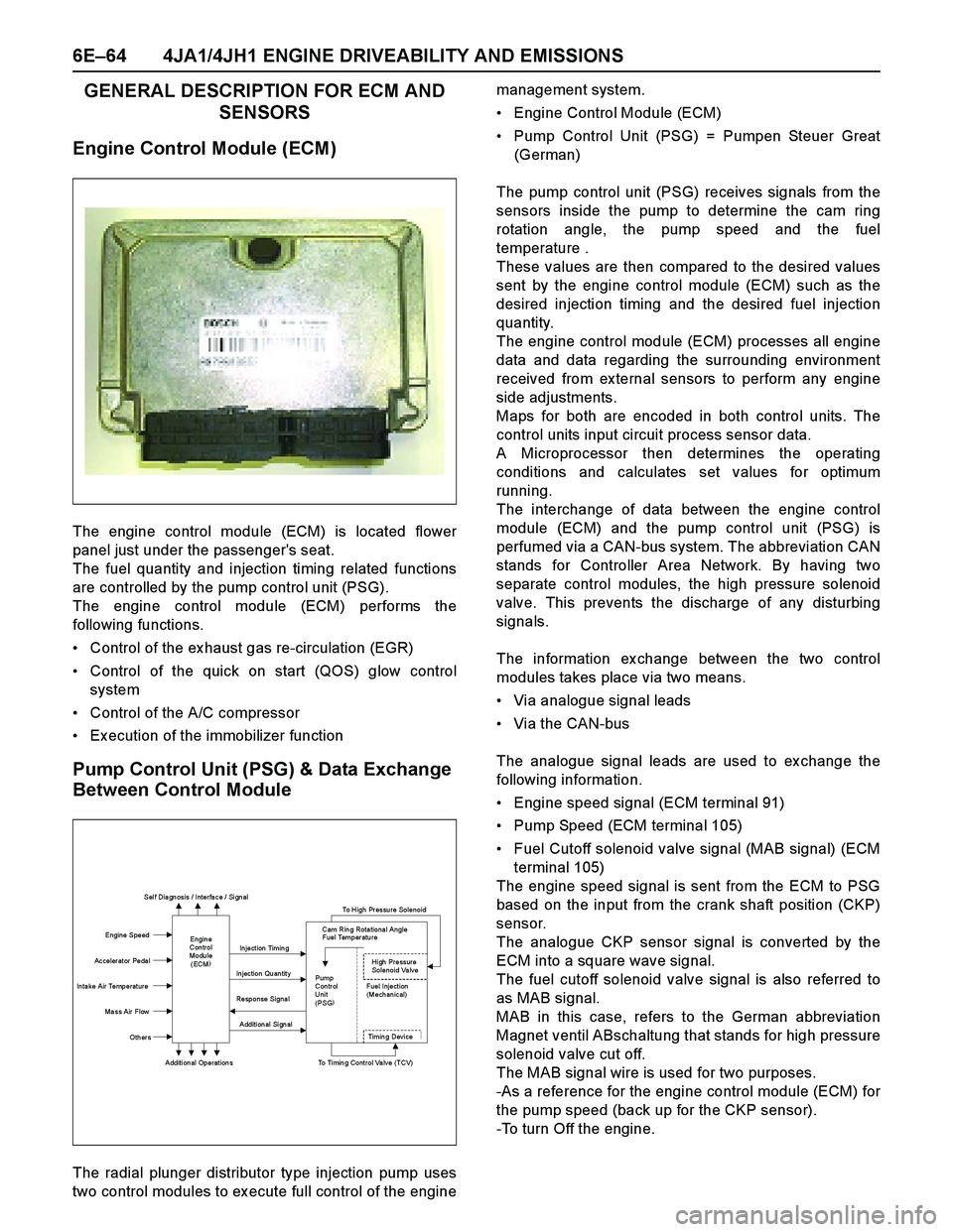
The engine control module (ECM) is located flower
panel just under the passenger's seat.
The fuel quantity and injection timing related functions
are controlled by the pump control unit (PSG).
The engine control module (ECM) performs the
following functions.
Control of the ex haust gas re-circulation (EGR)
Control of the quick on start (QOS) glow control
system
Control of the A/C compressor
Ex ecution of the immobilizer function
Pump Control Unit (PSG) & Data Exchange
Between Control Module
The radial plunger distributor type injection pump uses
two control modules to ex ecute full control of the enginemanagement system.
Engine Control Module (ECM)
Pump Control Unit (PSG) = Pumpen Steuer Great
(German)
The pump control unit (PSG) receives signals from the
sensors inside the pump to determine the cam ring
rotation angle, the pump speed and the fuel
temperature .
These values are then compared to the desired values
sent by the engine control module (ECM) such as the
desired injection timing and the desired fuel injection
quantity.
The engine control module (ECM) processes all engine
data and data regarding the surrounding environment
received from ex ternal sensors to perform any engine
side adjustments.
Maps for both are encoded in both control units. The
control units input circuit process sensor data.
A Microprocessor then determines the operating
conditions and calculates set values for optimum
running.
The interchange of data between the engine control
module (ECM) and the pump control unit (PSG) is
perfumed via a CAN-bus system. The abbreviation CAN
stands for Controller Area Network. By having two
separate control modules, the high pressure solenoid
valve. This prevents the discharge of any disturbing
signals.
The information ex change between the two control
modules takes place via two means.
Via analogue signal leads
Via the CAN-bus
The analogue signal leads are used to ex change the
following information.
Engine speed signal (ECM terminal 91)
Pump Speed (ECM terminal 105)
Fuel Cutoff solenoid valve signal (MAB signal) (ECM
terminal 105)
The engine speed signal is sent from the ECM to PSG
based on the input from the crank shaft position (CKP)
sensor.
The analogue CKP sensor signal is converted by the
ECM into a square wave signal.
The fuel cutoff solenoid valve signal is also referred to
as MAB signal.
MAB in this case, refers to the German abbreviation
Magnet ventil ABschaltung that stands for high pressure
solenoid v alv e cut off.
The MAB signal wire is used for two purposes.
-As a reference for the engine control module (ECM) for
the pump speed (back up for the CKP sensor).
-To turn Off the engine.
Sel f Dia gn osis / Interfa ce / Si gn al
To High Pressure Solenoid
Engine Speed
Injection Timing
Accelerator Pedal
Injection Quantity
In ta ke Air Temperat ure
Response Signal
Ma ss Air Flow
Additional Signal
Others
Additional Operations To Timing Control Valve (TCV)
Engin e
Con trol
Modu le
(ECM) Cam Rin g Rota tiona l Angle
Fuel Temper atu re
High Pressure
Solenoid Valve
Pump
Con tr ol Fuel Inject ion
Unit (Mechanical)
(PSG)
Ti m i n
g Devi ce
Page 1437 of 4264

4JA1/4JH1 ENGINE DRIVEABILITY AND EMISSIONS 6E–65
The following signals are ex changed via the CAN-bus:
From ECM to PSG
Desired injection quantity
Desired injection timing
Engine speed
From PSG to ECM
Fuel temperature
Pump speed
Cylinder identifier
Control pulse (actual injection quantity + actual
injection timing)
PSG status
Mass Air Flow (MAF) Sensor & Intake Air
Temperature (IAT) Sensor
The mass air flow (MAF) sensor is part of the intake air
system.
It is fitted between the air cleaner and turbocharger and
measure the mass air flowing into the engine.
The mass air flow (MAF) sensor uses a hot film element
to determine the amount of air flowing into the engine.
The mass air flow (MAF) sensor assembly consist of a
mass air flow (MAF) sensor element and an intake air
temperature sensor that are both ex posed to the air flow
to be measured.
The mass air flow (MAF) sensor element measures the
partial air mass through a measurement duct on the
sensor housing.
Using calibration, there is an ex trapolation to the entire
mass air flow to the engine.The IAT sensor is a thermistor. A temperature changes
the resistance value. And it changes voltage. In other
words it measures a temperature value. Low air
temperature produces a high resistance.
The ECM supplies 5 volts signal to the IAT sensor
through resisters in the ECM and measures the voltage.
The signal voltage will be high when the air temperature
is cold, and it will be low when the air temperature is
hot.
(1) Air Cleaner Case
(2) Mass Air Flow (MAF) & Intake Air Temperature
(IAT) Sensor
1 2
Characteristic of IAT Sensor -Reference-
10 100 1000 10000 100000
-30 -20 -10 0 10 20 30 40 50 60 70 80 90 100 110
Intake Air Temp. (deg. C) (Tech2 Reading)
Resistance (ohm) (Solid Line)
Page 1438 of 4264
6E–66 4JA1/4JH1 ENGINE DRIVEABILITY AND EMISSIONS
Throttle Position Sensor (TPS)
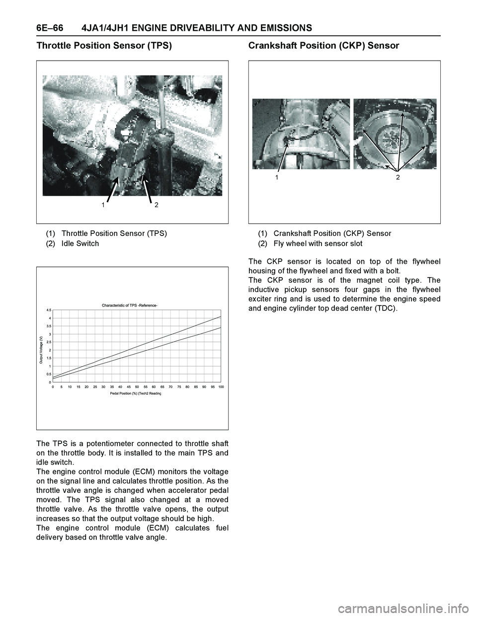
The TPS is a potentiometer connected to throttle shaft
on the throttle body. It is installed to the main TPS and
idle switch.
The engine control module (ECM) monitors the voltage
on the signal line and calculates throttle position. As the
throttle valve angle is changed when accelerator pedal
moved. The TPS signal also changed at a moved
throttle valve. As the throttle valve opens, the output
increases so that the output voltage should be high.
The engine control module (ECM) calculates fuel
delivery based on throttle valve angle.
Crankshaft Position (CKP) Sensor
The CKP sensor is located on top of the flywheel
housing of the flywheel and fix ed with a bolt.
The CKP sensor is of the magnet coil type. The
inductive pickup sensors four gaps in the flywheel
ex citer ring and is used to determine the engine speed
and engine cylinder top dead center (TDC). (1) Throttle Position Sensor (TPS)
(2) Idle Switch
1 2
Characteristic of TPS -Reference-
0 0.51 1.52 2.53 3.54 4.5
0 5 10 15 20 25 30 35 40 45 50 55 60 65 70 75 80 85 90 95 100
Pedal Position (%) (Tech2 Readin
g
Output Voltage (V)
(1) Crankshaft Position (CKP) Sensor
(2) Fly wheel with sensor slot
1 2
Page 1442 of 4264
6E–70 4JA1/4JH1 ENGINE DRIVEABILITY AND EMISSIONS
GENERAL DESCRIPTION FOR INJECTION
PUMP
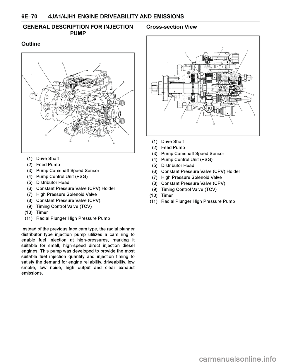
Outline
Instead of the previous face cam type, the radial plunger
distributor type injection pump utilizes a cam ring to
enable fuel injection at high-pressures, marking it
suitable for small, high-speed direct injection diesel
engines. This pump was developed to provide the most
suitable fuel injection quantity and injection timing to
satisfy the demand for engine reliability, driveability, low
smoke, low noise, high output and clear ex haust
emissions.
Cross-section View
(1) Drive Shaft
(2) Feed Pump
(3) Pump Camshaft Speed Sensor
(4) Pump Control Unit (PSG)
(5) Distributor Head
(6) Constant Pressure Valve (CPV) Holder
(7) High Pressure Solenoid Valve
(8) Constant Pressure Valve (CPV)
(9) Timing Control Valve (TCV)
(10) Timer
(11) Radial Plunger High Pressure Pump
(1) Drive Shaft
(2) Feed Pump
(3) Pump Camshaft Speed Sensor
(4) Pump Control Unit (PSG)
(5) Distributor Head
(6) Constant Pressure Valve (CPV) Holder
(7) High Pressure Solenoid Valve
(8) Constant Pressure Valve (CPV)
(9) Timing Control Valve (TCV)
(10) Timer
(11) Radial Plunger High Pressure Pump
Page 1444 of 4264
6E–72 4JA1/4JH1 ENGINE DRIVEABILITY AND EMISSIONS
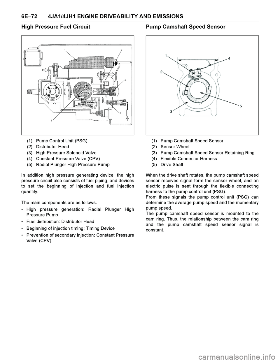
High Pressure Fuel Circuit
In addition high pressure generating device, the high
pressure circuit also consists of fuel piping, and devices
to set the beginning of injection and fuel injection
quantity.
The main components are as follows.
High pressure generation: Radial Plunger High
Pressure Pump
Fuel distribution: Distributor Head
Beginning of injection timing: Timing Device
Prevention of secondary injection: Constant Pressure
Valve (CPV)
Pump Camshaft Speed Sensor
When the drive shaft rotates, the pump camshaft speed
sensor receives signal form the sensor wheel, and an
electric pulse is sent through the flex ible connecting
harness to the pump control unit (PSG).
From these signals the pump control unit (PSG) can
determine the average pump speed and the momentary
pump speed.
The pump camshaft speed sensor is mounted to the
cam ring. Thus, the relationship between the cam ring
and the pump camshaft speed sensor signal is
constant. (1) Pump Control Unit (PSG)
(2) Distributor Head
(3) High Pressure Solenoid Valve
(4) Constant Pressure Valve (CPV)
(5) Radial Plunger High Pressure Pump
(1) Pump Camshaft Speed Sensor
(2) Sensor Wheel
(3) Pump Camshaft Speed Sensor Retaining Ring
(4) Flex ible Connector Harness
(5) Drive Shaft
Page 1445 of 4264
4JA1/4JH1 ENGINE DRIVEABILITY AND EMISSIONS 6E–73
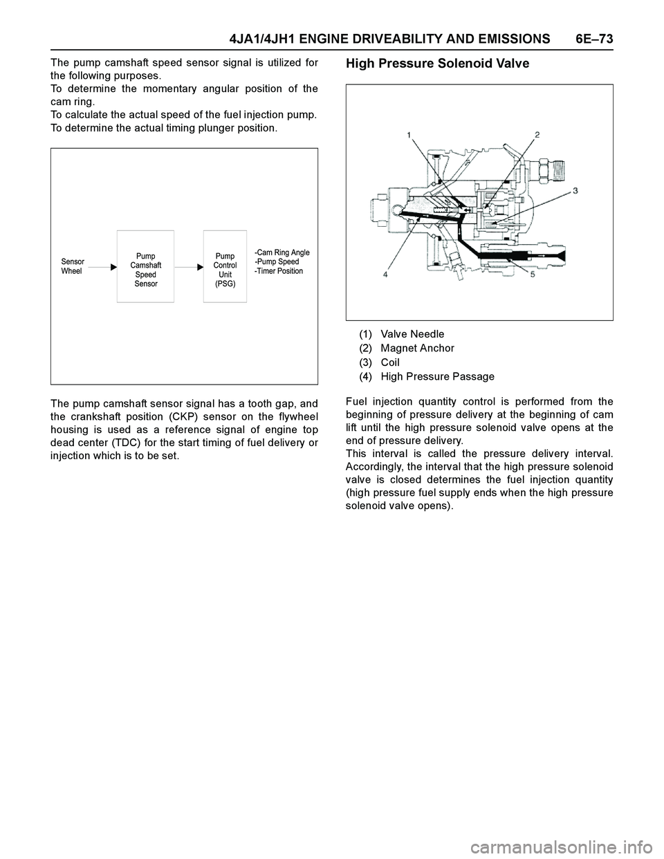
The pump camshaft speed sensor signal is utilized for
the following purposes.
To determine the momentary angular position of the
cam ring.
To calculate the actual speed of the fuel injection pump.
To determine the actual timing plunger position.
The pump camshaft sensor signal has a tooth gap, and
the crankshaft position (CKP) sensor on the flywheel
housing is used as a reference signal of engine top
dead center (TDC) for the start timing of fuel delivery or
injection which is to be set.High Pressure Solenoid Valve
Fuel injection quantity control is performed from the
beginning of pressure delivery at the beginning of cam
lift until the high pressure solenoid valve opens at the
end of pressure delivery.
This interval is called the pressure delivery interval.
Accordingly, the interval that the high pressure solenoid
valve is closed determines the fuel injection quantity
(high pressure fuel supply ends when the high pressure
solenoid valve opens).
-Cam Ring Angle
Sensor -Pump Speed
Wheel -Timer PositionPump
Control
Unit
(PSG)Pump
Camshaft
Speed
Sensor
(1) Valve Needle
(2) Magnet Anchor
(3) Coil
(4) High Pressure Passage