fuse ISUZU TF SERIES 2004 User Guide
[x] Cancel search | Manufacturer: ISUZU, Model Year: 2004, Model line: TF SERIES, Model: ISUZU TF SERIES 2004Pages: 4264, PDF Size: 72.63 MB
Page 85 of 4264
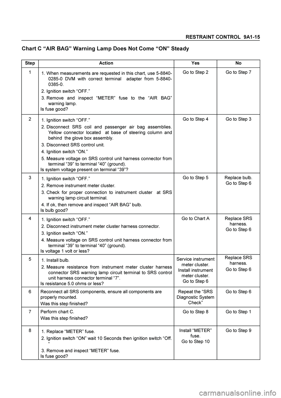
RESTRAINT CONTROL 9A1-15
Chart C “AIR BAG” Warning Lamp Does Not Come “ON” Steady
Step Action Yes No
1
1. When measurements are requested in this chart, use 5-8840-
0285-0 DVM with correct terminal adapter from 5-8840-
0385-0.
2. Ignition switch “OFF.”
3. Remove and inspect “METER” fuse to the “AIR BAG”
warning lamp.
Is fuse good? Go to Step 2 Go to Step 7
2
1. Ignition switch “OFF.”
2. Disconnect SRS coil and passenger air bag assemblies.
Yellow connector located at base of steering column and
behind the glove box assembly.
3. Disconnect SRS control unit.
4. Ignition switch “ON.”
5. Measure voltage on SRS control unit harness connector from
terminal “39” to terminal “40” (ground).
Is system voltage present on terminal “39”? Go to Step 4 Go to Step 3
3
1. Ignition switch “OFF.”
2. Remove instrument meter cluster.
3. Check for proper connection to instrument cluster at SRS
warning lamp circuit terminal.
4. If ok, then remove and inspect “AIR BAG” bulb.
Is bulb good? Go to Step 5 Replace bulb.
Go to Step 6
4
1. Ignition switch “OFF.”
2. Disconnect instrument meter cluster harness connector.
3. Ignition switch “ON.”
4. Measure voltage on SRS control unit harness connector from
terminal “39” to terminal “40” (ground).
Is voltage 1 volt or less? Go to Chart A Replace SRS
harness.
Go to Step 6
5
1. Install bulb.
2. Measure resistance from instrument meter cluster harness
connector SRS warning lamp circuit terminal to SRS control
unit harness connector terminal “7”.
Is resistance 5.0 ohms or less? Service instrument
meter cluster.
Install instrument
meter cluster.
Go to Step 6 Replace SRS
harness.
Go to Step 6
6 Reconnect all SRS components, ensure all components are
properly mounted.
Was this step finished? Repeat the “SRS
Diagnostic System
Check” Go to Step 6
7 Perform chart C.
Was this step finished? Go to Step 8 Go to Step 1
8
1. Replace “METER” fuse.
2. Ignition switch “ON” wait 10 Seconds then ignition switch “Off.
“
3. Remove and inspect “METER” fuse.
Is fuse good? Install “METER”
fuse.
Go to Step 10 Go to Step 9
Page 86 of 4264
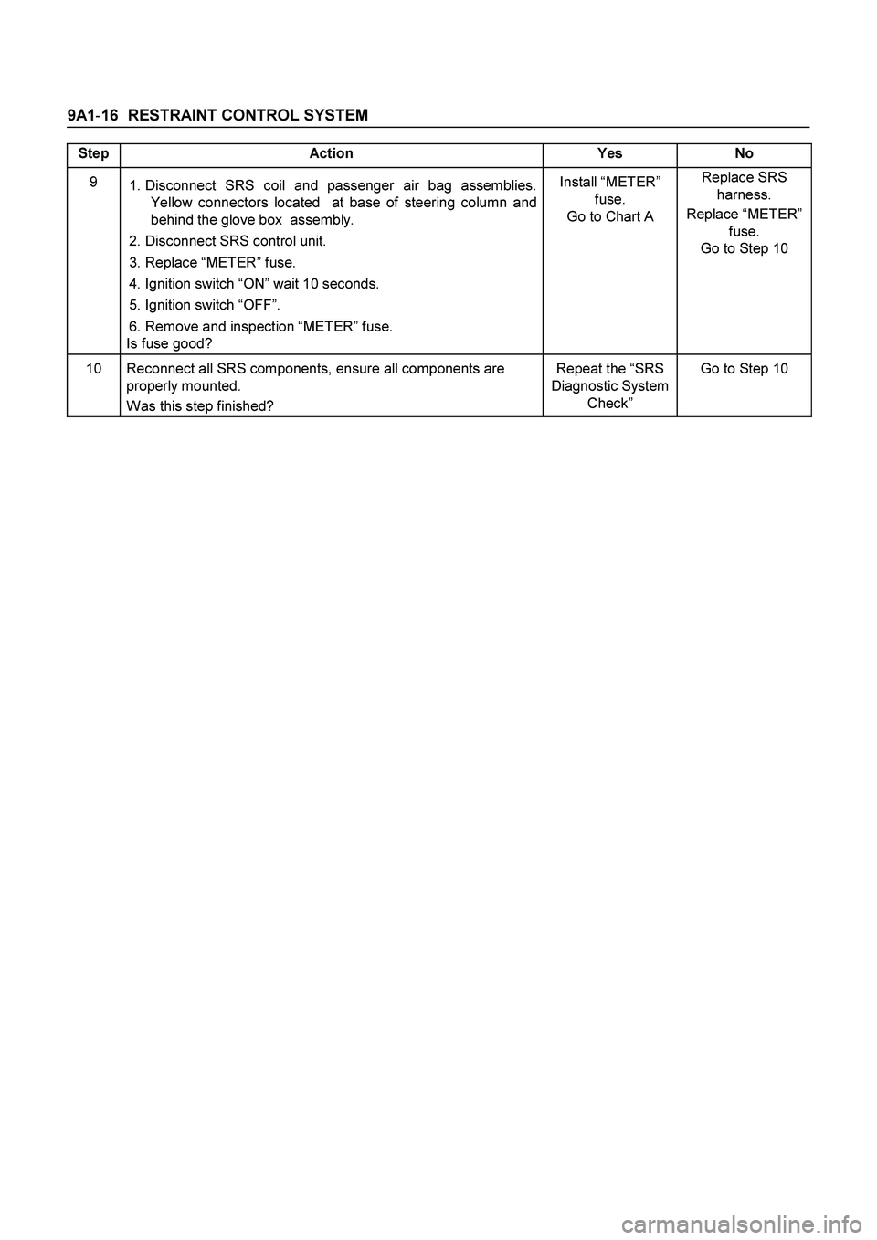
9A1-16 RESTRAINT CONTROL SYSTEM
Step Action Yes No
9
1. Disconnect SRS coil and passenger air bag assemblies.
Yellow connectors located at base of steering column and
behind the glove box assembly.
2. Disconnect SRS control unit.
3. Replace “METER” fuse.
4. Ignition switch “ON” wait 10 seconds.
5. Ignition switch “OFF”.
6. Remove and inspection “METER” fuse.
Is fuse good? Install “METER”
fuse.
Go to Chart A Replace SRS
harness.
Replace “METER”
fuse.
Go to Step 10
10 Reconnect all SRS components, ensure all components are
properly mounted.
Was this step finished? Repeat the “SRS
Diagnostic System
Check” Go to Step 10
Page 330 of 4264
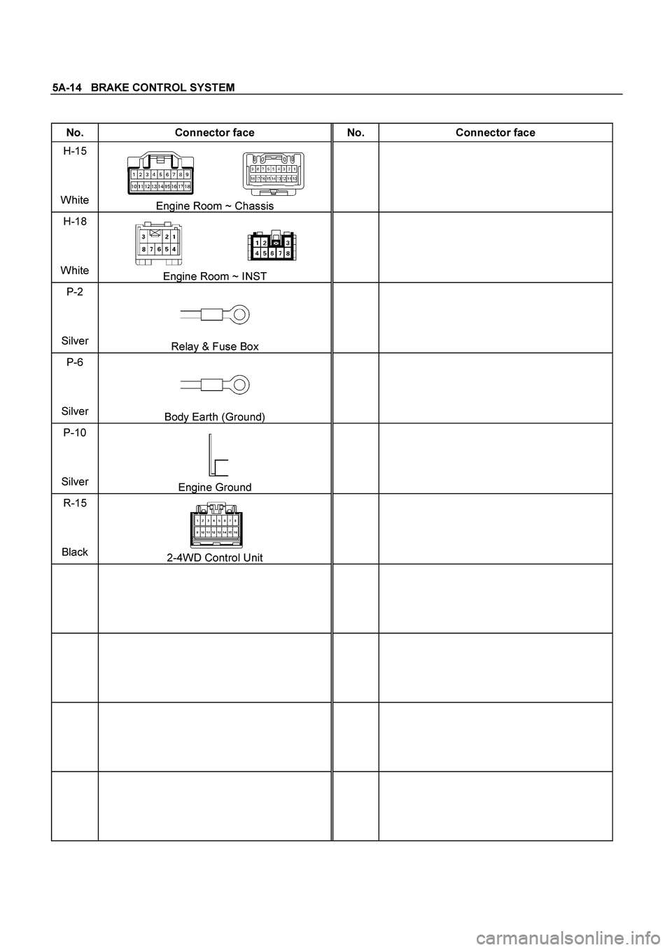
5A-14 BRAKE CONTROL SYSTEM
No. Connector face No. Connector face
H-15
White
Engine Room ~ Chassis
H-18
White
Engine Room ~ INST
P-2
Silver
Relay & Fuse Box
P-6
Silver
Body Earth (Ground)
P-10
Silver
Engine Ground
R-15
Black
2-4WD Control Unit
Page 337 of 4264
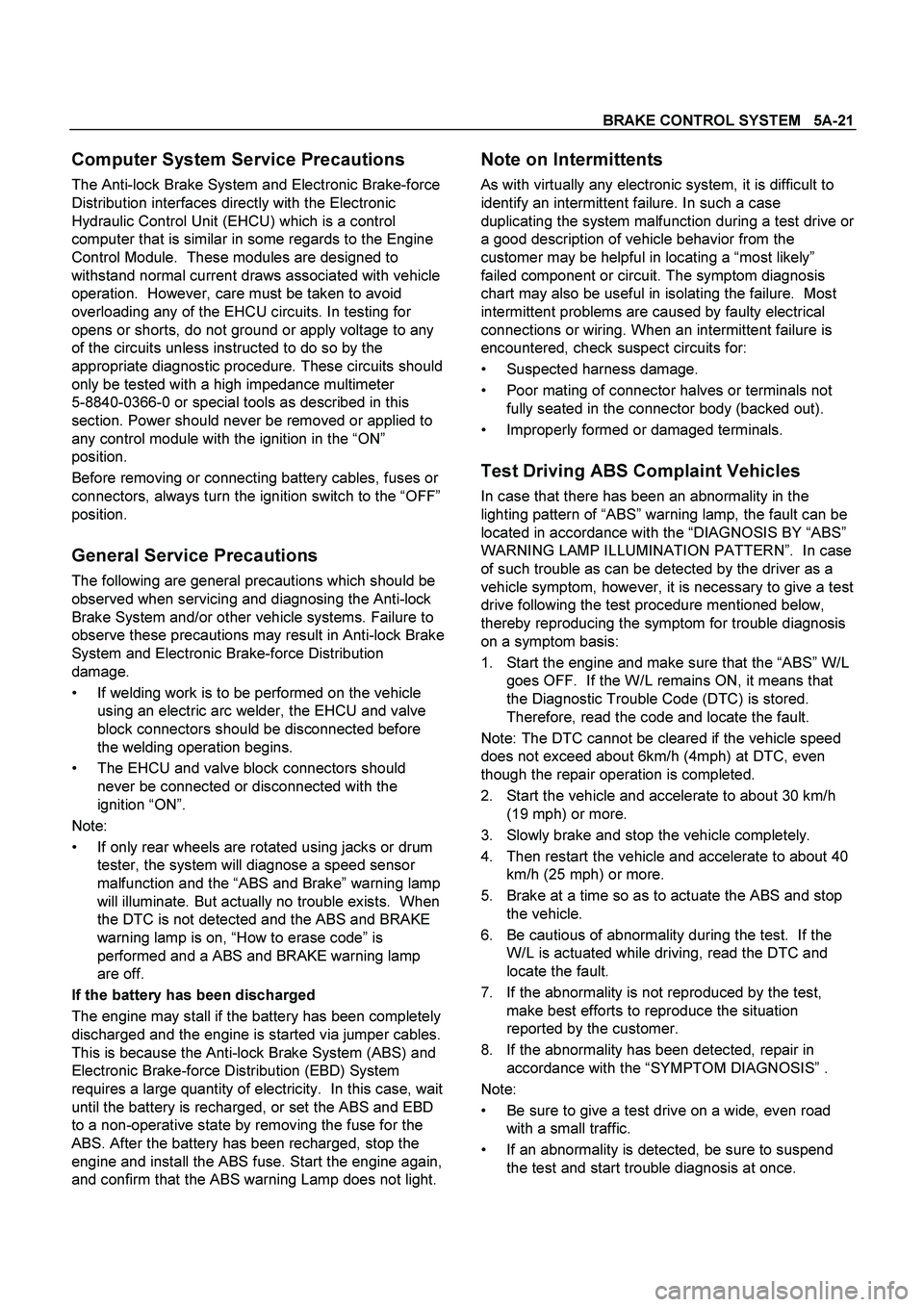
BRAKE CONTROL SYSTEM 5A-21
Computer System Service Precautions
The Anti-lock Brake System and Electronic Brake-force
Distribution interfaces directly with the Electronic
Hydraulic Control Unit (EHCU) which is a control
computer that is similar in some regards to the Engine
Control Module. These modules are designed to
withstand normal current draws associated with vehicle
operation. However, care must be taken to avoid
overloading any of the EHCU circuits. In testing for
opens or shorts, do not ground or apply voltage to any
of the circuits unless instructed to do so by the
appropriate diagnostic procedure. These circuits should
only be tested with a high impedance multimeter
5-8840-0366-0 or special tools as described in this
section. Power should never be removed or applied to
any control module with the ignition in the “ON”
position.
Before removing or connecting battery cables, fuses or
connectors, always turn the ignition switch to the “OFF”
position.
General Service Precautions
The following are general precautions which should be
observed when servicing and diagnosing the Anti-lock
Brake System and/or other vehicle systems. Failure to
observe these precautions may result in Anti-lock Brake
System and Electronic Brake-force Distribution
damage.
If welding work is to be performed on the vehicle
using an electric arc welder, the EHCU and valve
block connectors should be disconnected before
the welding operation begins.
The EHCU and valve block connectors should
never be connected or disconnected with the
ignition “ON”.
Note:
If only rear wheels are rotated using jacks or drum
tester, the system will diagnose a speed sensor
malfunction and the “ABS and Brake” warning lamp
will illuminate. But actually no trouble exists. When
the DTC is not detected and the ABS and BRAKE
warning lamp is on, “How to erase code” is
performed and a ABS and BRAKE warning lamp
are off.
If the battery has been discharged
The engine may stall if the battery has been completely
discharged and the engine is started via jumper cables.
This is because the Anti-lock Brake System (ABS) and
Electronic Brake-force Distribution (EBD) System
requires a large quantity of electricity. In this case, wait
until the battery is recharged, or set the ABS and EBD
to a non-operative state by removing the fuse for the
ABS. After the battery has been recharged, stop the
engine and install the ABS fuse. Start the engine again,
and confirm that the ABS warning Lamp does not light.
Note on Intermittents
As with virtually any electronic system, it is difficult to
identify an intermittent failure. In such a case
duplicating the system malfunction during a test drive or
a good description of vehicle behavior from the
customer may be helpful in locating a “most likely”
failed component or circuit. The symptom diagnosis
chart may also be useful in isolating the failure. Most
intermittent problems are caused by faulty electrical
connections or wiring. When an intermittent failure is
encountered, check suspect circuits for:
Suspected harness damage.
Poor mating of connector halves or terminals not
fully seated in the connector body (backed out).
Improperly formed or damaged terminals.
Test Driving ABS Complaint Vehicles
In case that there has been an abnormality in the
lighting pattern of “ABS” warning lamp, the fault can be
located in accordance with the “DIAGNOSIS BY “ABS”
WARNING LAMP ILLUMINATION PATTERN”. In case
of such trouble as can be detected by the driver as a
vehicle symptom, however, it is necessary to give a test
drive following the test procedure mentioned below,
thereby reproducing the symptom for trouble diagnosis
on a symptom basis:
1.
Start the engine and make sure that the “ABS” W/L
goes OFF. If the W/L remains ON, it means that
the Diagnostic Trouble Code (DTC) is stored.
Therefore, read the code and locate the fault.
Note: The DTC cannot be cleared if the vehicle speed
does not exceed about 6km/h (4mph) at DTC, even
though the repair operation is completed.
2. Start the vehicle and accelerate to about 30 km/h
(19 mph) or more.
3. Slowly brake and stop the vehicle completely.
4. Then restart the vehicle and accelerate to about 40
km/h (25 mph) or more.
5. Brake at a time so as to actuate the ABS and stop
the vehicle.
6. Be cautious of abnormality during the test. If the
W/L is actuated while driving, read the DTC and
locate the fault.
7. If the abnormality is not reproduced by the test,
make best efforts to reproduce the situation
reported by the customer.
8. If the abnormality has been detected, repair in
accordance with the “SYMPTOM DIAGNOSIS” .
Note:
Be sure to give a test drive on a wide, even road
with a small traffic.
If an abnormality is detected, be sure to suspend
the test and start trouble diagnosis at once.
Page 357 of 4264
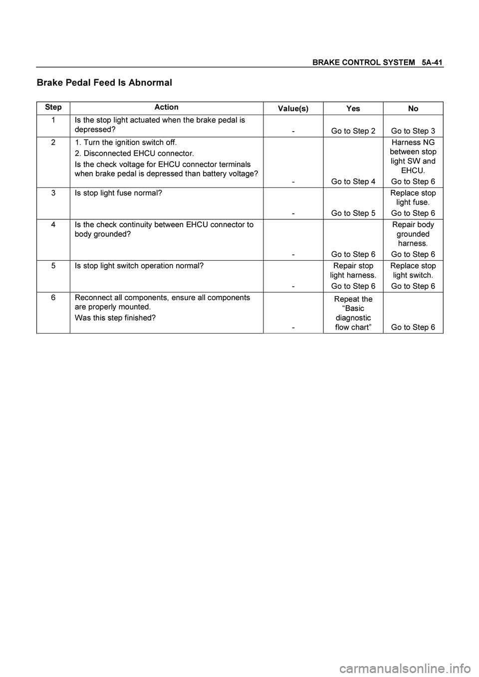
BRAKE CONTROL SYSTEM 5A-41
Brake Pedal Feed Is Abnormal
Step Action
Value(s) Yes No
1 Is the stop light actuated when the brake pedal is
depressed?
- Go to Step 2 Go to Step 3
2 1. Turn the ignition switch off.
2. Disconnected EHCU connector.
Is the check voltage for EHCU connector terminals
when brake pedal is depressed than battery voltage?
- Go to Step 4 Harness NG
between stop
light SW and
EHCU.
Go to Step 6
3 Is stop light fuse normal?
- Go to Step 5 Replace stop
light fuse.
Go to Step 6
4 Is the check continuity between EHCU connector to
body grounded?
- Go to Step 6 Repair body
grounded
harness.
Go to Step 6
5 Is stop light switch operation normal?
- Repair stop
light harness.
Go to Step 6 Replace stop
light switch.
Go to Step 6
6 Reconnect all components, ensure all components
are properly mounted.
Was this step finished?
- Repeat the
“Basic
diagnostic
flow chart” Go to Step 6
Page 359 of 4264

BRAKE CONTROL SYSTEM 5A-43
No ABS Warning Lamp
Step Action
Value(s) Yes No
1 Check the meter fuse for the instrument cluster
ignition feed circuit.
Is the fuse OK? - Go to Step 3 Go to Step 2
2 Replace the fuse.
Is the action complete? - Verify repair
Go to Step 3 -
3 1. Ignition “OFF,” disconnect the EHCU.
2. Ignition “ON,”engine “OFF.”
3. Observe the ABS warning lamp.
Is the ABS warning lamp “ON”?
- Go to Step 5 Go to Step 4
4 Repair or replace the meter circuit or meter.
Is the action complete? - Verify repair -
5 1. Check the EHCU circuit for an open, short to
ground, or short to voltage. Also, check the EHCU
ignition feed circuit for an open or short to ground
and the EHCU ground circuit for an open.
2. If a problem is found, repair as necessary.
Was a problem found?
- Verify repair Go to Step 6
6 1. Ignition “OFF,” reconnect the EHCU.
2. Ignition “ON,”engine “OFF.”
3. Observe the ABS warning lamp.
Is the ABS warning lamp “ON”?
- Verify repair Go to Step 7
7 Replace EHCU.
Note : Check the EHCU type for specification, the
EHCU is replaced.
(Specification; 2WD or 4WD Model)
Is the action complete? - Verify repair -
Page 659 of 4264
ELECTRICAL-BODY AND CHASSIS 8A-1
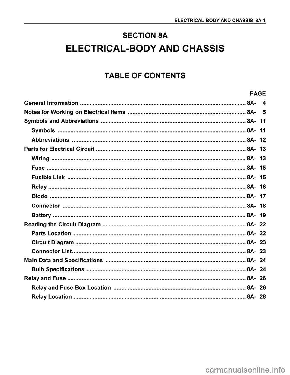
SECTION 8A
ELECTRICAL-BODY AND CHASSIS
TABLE OF CONTENTS
PAGE
General Information ........................................................................................................ 8A- 4
Notes for Working on Electrical Items .......................................................................... 8A- 5
Symbols and Abbreviations ........................................................................................... 8A- 11
Symbols ...................................................................................................................... 8A- 11
Abbreviations ............................................................................................................. 8A- 12
Parts for Electrical Circuit .............................................................................................. 8A- 13
Wiring .......................................................................................................................... 8A- 13
Fuse ............................................................................................................................. 8A- 15
Fusible Link ................................................................................................................ 8A- 15
Relay ............................................................................................................................ 8A- 16
Diode ........................................................................................................................... 8A- 17
Connector ................................................................................................................... 8A- 18
Battery ......................................................................................................................... 8A- 19
Reading the Circuit Diagram .......................................................................................... 8A- 22
Parts Location ............................................................................................................ 8A- 22
Circuit Diagram ........................................................................................................... 8A- 23
Connector List ............................................................................................................. 8A- 23
Main Data and Specifications ........................................................................................ 8A- 24
Bulb Specifications .................................................................................................... 8A- 24
Relay and Fuse ................................................................................................................ 8A- 26
Relay and Fuse Box Location ................................................................................... 8A- 26
Relay Location ............................................................................................................ 8A- 28
Page 660 of 4264
8A-2 ELECTRICAL-BODY AND CHASSIS
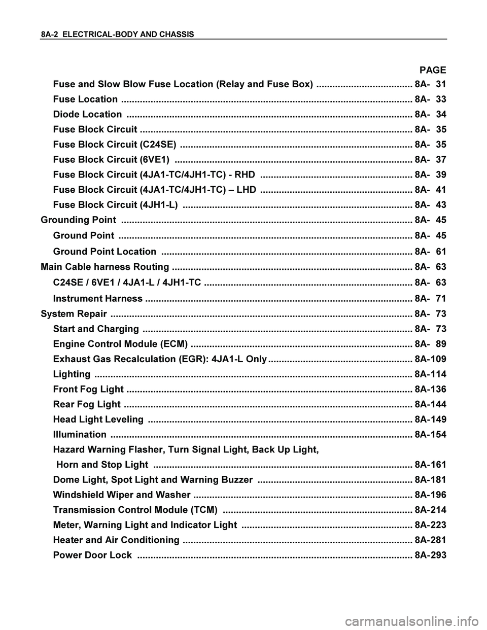
PAGE
Fuse and Slow Blow Fuse Location (Relay and Fuse Box) .................................... 8A- 31
Fuse Location ............................................................................................................. 8A- 33
Diode Location ........................................................................................................... 8A- 34
Fuse Block Circuit ...................................................................................................... 8A- 35
Fuse Block Circuit (C24SE) ....................................................................................... 8A- 35
Fuse Block Circuit (6VE1) ......................................................................................... 8A- 37
Fuse Block Circuit (4JA1-TC/4JH1-TC) - RHD ......................................................... 8A- 39
Fuse Block Circuit (4JA1-TC/4JH1-TC) – LHD ......................................................... 8A- 41
Fuse Block Circuit (4JH1-L) ...................................................................................... 8A- 43
Grounding Point ............................................................................................................. 8A- 45
Ground Point .............................................................................................................. 8A- 45
Ground Point Location .............................................................................................. 8A- 61
Main Cable harness Routing .......................................................................................... 8A- 63
C24SE / 6VE1 / 4JA1-L / 4JH1-TC .............................................................................. 8A- 63
Instrument Harness .................................................................................................... 8A- 71
System Repair .................................................................................................................8A- 73
Start and Charging ..................................................................................................... 8A- 73
Engine Control Module (ECM) ................................................................................... 8A- 89
Exhaust Gas Recalculation (EGR): 4JA1-L Only ...................................................... 8A- 109
Lighting ....................................................................................................................... 8A- 114
Front Fog Light ........................................................................................................... 8A- 136
Rear Fog Light ............................................................................................................ 8A- 144
Head Light Leveling ................................................................................................... 8A- 149
Illumination ................................................................................................................. 8A- 154
Hazard Warning Flasher, Turn Signal Light, Back Up Light,
Horn and Stop Light ................................................................................................. 8A- 161
Dome Light, Spot Light and Warning Buzzer .......................................................... 8A- 181
Windshield Wiper and Washer .................................................................................. 8A- 196
Transmission Control Module (TCM) ....................................................................... 8A- 214
Meter, Warning Light and Indicator Light ................................................................ 8A- 223
Heater and Air Conditioning ...................................................................................... 8A- 281
Power Door Lock ....................................................................................................... 8A- 293
Page 662 of 4264
8A-4 ELECTRICAL-BODY AND CHASSIS
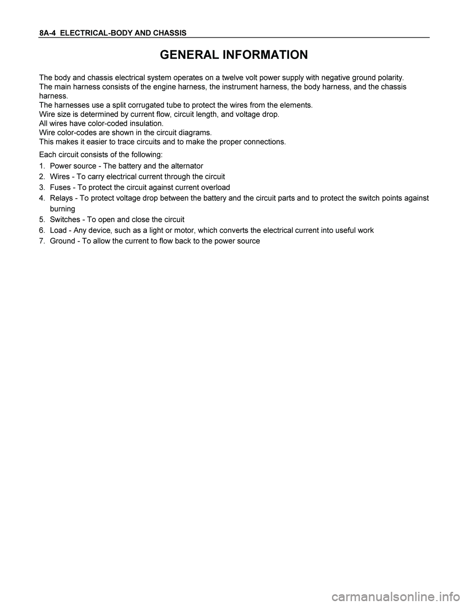
GENERAL INFORMATION
The body and chassis electrical system operates on a twelve volt power supply with negative ground polarity.
The main harness consists of the engine harness, the instrument harness, the body harness, and the chassis
harness.
The harnesses use a split corrugated tube to protect the wires from the elements.
Wire size is determined by current flow, circuit length, and voltage drop.
All wires have color-coded insulation.
Wire color-codes are shown in the circuit diagrams.
This makes it easier to trace circuits and to make the proper connections.
Each circuit consists of the following:
1. Power source - The battery and the alternator
2. Wires - To carry electrical current through the circuit
3. Fuses - To protect the circuit against current overload
4. Relays - To protect voltage drop between the battery and the circuit parts and to protect the switch points against
burning
5. Switches - To open and close the circuit
6. Load - Any device, such as a light or motor, which converts the electrical current into useful work
7. Ground - To allow the current to flow back to the power source
Page 665 of 4264
ELECTRICAL-BODY AND CHASSIS 8A-7
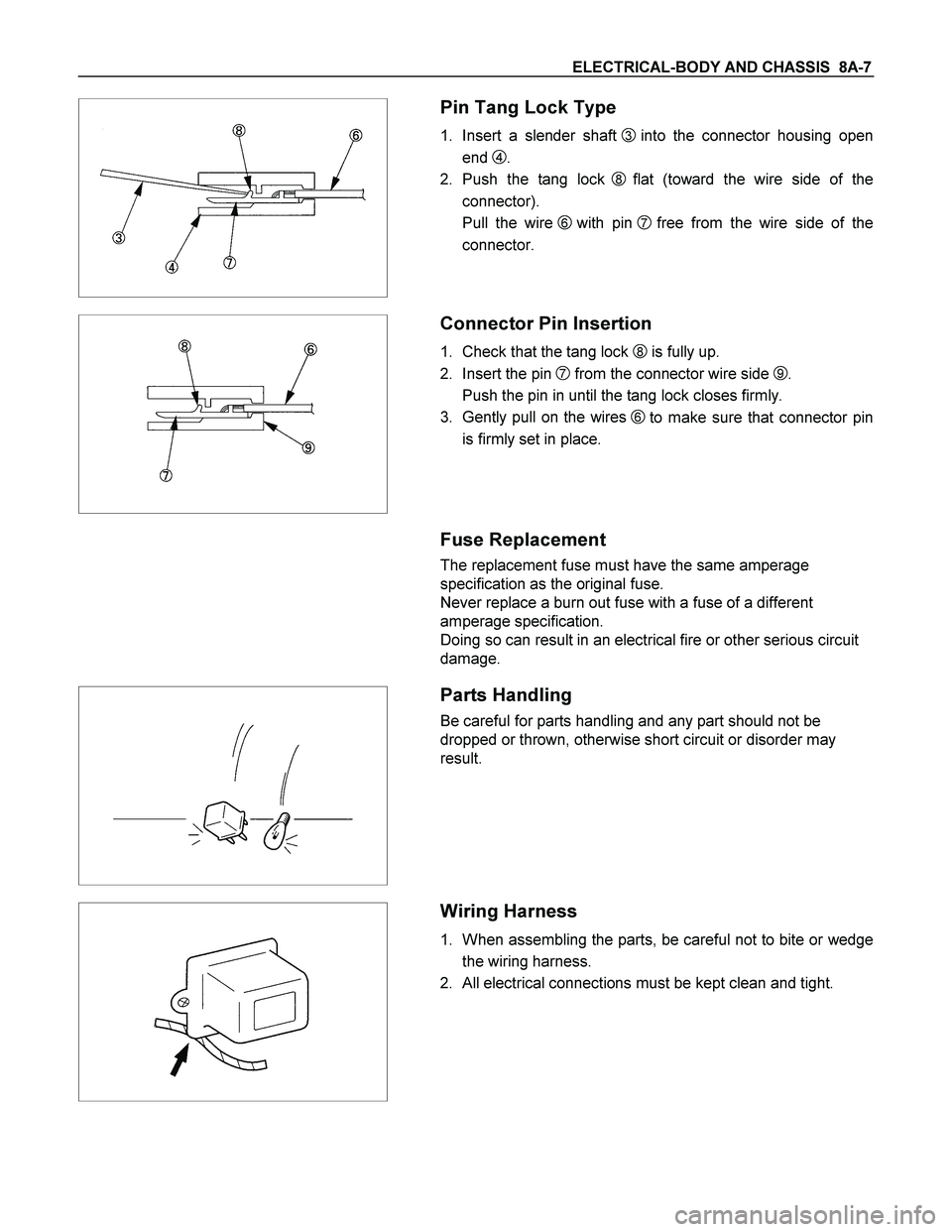
Pin Tang Lock Type
1. Insert a slender shaft 3 into the connector housing open
end
4.
2. Push the tang lock
8flat (toward the wire side of the
connector).
Pull the wire
6 with pin 7free from the wire side of the
connector.
Connector Pin Insertion
1. Check that the tang lock 8 is fully up.
2. Insert the pin
7 from the connector wire side 9.
Push the pin in until the tang lock closes firmly.
3. Gently pull on the wires
6to make sure that connector pin
is firmly set in place.
Fuse Replacement
The replacement fuse must have the same amperage
specification as the original fuse.
Never replace a burn out fuse with a fuse of a different
amperage specification.
Doing so can result in an electrical fire or other serious circuit
damage.
Parts Handling
Be careful for parts handling and any part should not be
dropped or thrown, otherwise short circuit or disorder may
result.
Wiring Harness
1. When assembling the parts, be careful not to bite or wedge
the wiring harness.
2. All electrical connections must be kept clean and tight.