Front axle ISUZU TFS SERIES 1997 Owner's Manual
[x] Cancel search | Manufacturer: ISUZU, Model Year: 1997, Model line: TFS SERIES, Model: ISUZU TFS SERIES 1997Pages: 1600, PDF Size: 40.98 MB
Page 142 of 1600

FRONT WHEEL DRIVE 4C1-79
(4) Align setting marks (1) and join the yokes.
(5) Install snap ring.
NOTE:
Discard used snap rings and install new ones.
When the bearing cap is in position, select and attach a snap
ring of suitable thickness so that the end play of the spider pin
is held within 0.1mm (0.004 in).
T/F side for Type - A and B
Snap ring thickness and Identification color
1.5mm (0.059 in); Blue
1.53mm (0.060 in); White
1.59mm (0.063 in); Yellow
1.62mm (0.064 in); Green
1.68mm (0.066 in); Not colored
Axle side for Type - A
1.44mm (0.057 in); Not colored
1.49mm (0.059 in); Not colored
1.54mm (0.061 in); Not colored
NOTE:
Be sure to use snap rings of the same thickness on both sides.
Page 143 of 1600

4C1-80 FRONT WHEEL DRIVE
TROUBLESHOOTING
Refer to this Section to quickly diagnose and repair front axle problems. Each troubleshooting chart has three
headings arranged from left to right.
(1) Checkpoint (2) Trouble Cause (3) Countermeasure
This Section is divided into ten sub-sections:
42 Model
1. Wanders and pulls
2. Front wheel shimmy
44 Model
1. Oil leak at front axle
2. Oil leak at pinion shaft
3. Noises in front axle drive shaft joint
4. Noises in front axle
5. Wanders and pulls
6. Front wheel shimmy
7. Automatic locking free wheel hub
1) Does not lock or locks only on one side
2) Does not freewheel or freewheels only to one side
3) Noises in automatic locking free wheel hub
Propeller shaft
1. Noise
2. Vibration
Page 146 of 1600

FRONT WHEEL DRIVE 4C1-83
44 MODEL
1. OIL LEAK AT FRONT AXLE
Checkpoint Trouble Cause Countermeasure
Front axle housingRepair or replaceCracked
Replace the oil sealW orn or defective oil seal
NG NG
OKOil seal
2. OIL LEAK AT PINION SHAFT
Oil sealReplace the oil sealW orn or defective
Correct the oil levelToo much gear oil
NG NG
OKGear oil level
Pinion flangeTighten or replaceLoose or damaged NG OK
3. NOISES IN FRONT AXLE DRIVE SHAFT JOINT
Replace the drive shaft joints
and bellowsBroken or worn NGDrive shaft joints and bellows
(B.J and DOJ)
Page 147 of 1600

4C1-84 FRONT WHEEL DRIVE
4. NOISES IN FRONT AXLE
Checkpoint Trouble Cause Countermeasure
Replenish the gear oilInsufficient gear oil NG
Replace the wheel bearing
Replace the pinion shaft
bearing
Replace the ring gear pinion
gear or side gear
Replace the gear oil
W heel bearingWorn
Pinion shaft bearingWorn
W orn or chipped
W rong or poor grade gear oil
Ring gear, pinion gear or side
gear
Adjust the backlashDrive pinion to ring gear
backlashToo much or too little backlash
NG NG NG NG NG
OK OK
OK
OK
Oil level
Tighten or replaceDifferential bearingLoose or worn NG OK
Page 151 of 1600

4C1-88 FRONT WHEEL DRIVE
(3) NOISES IN AUTOMATIC LOCKING FREE WHEEL HUB
Note :
Some noise at the time of shifting from
“LOCK” to “FREE” or vice versa is normal.
It is not a sign of trouble.
Checkpoint Trouble Cause Countermeasure
Operating of automatic locking
free wheel hubReplace the driven clutchOne side operating
Connect the axial play or
replace the driven clutchExcessive axial play
NG NG
OKHoldout ring axial play
Front axle or jointReplace or tightenDamaged or loose NG OK
Page 345 of 1600
BRAKES 5-17
Secondary master
cylinder fluid
pressure
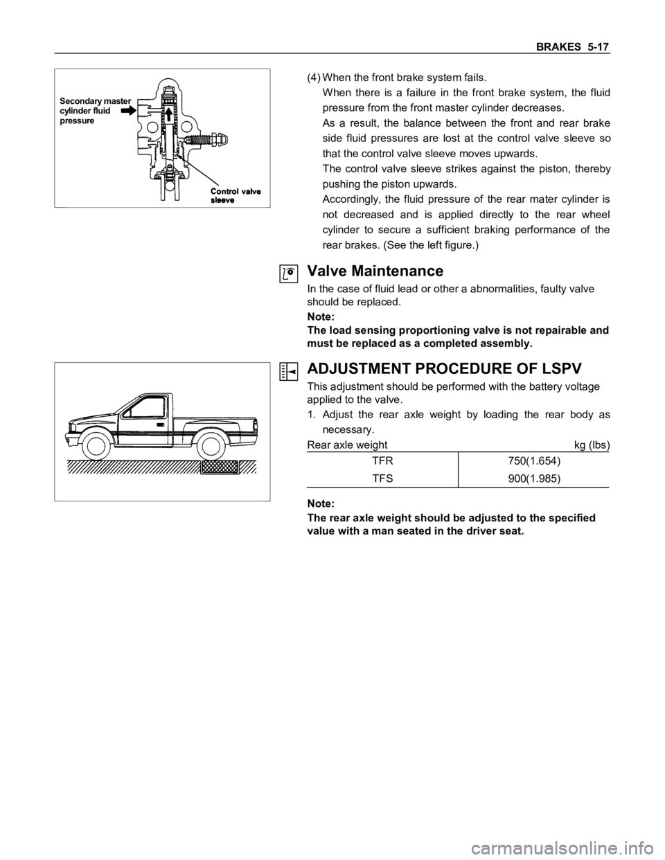
(4) When the front brake system fails.
W hen there is a failure in the front brake system, the fluid
pressure from the front master cylinder decreases.
As a result, the balance between the front and rear brake
side fluid pressures are lost at the control valve sleeve so
that the control valve sleeve moves upwards.
The control valve sleeve strikes against the piston, thereby
pushing the piston upwards.
Accordingly, the fluid pressure of the rear mater cylinder is
not decreased and is applied directly to the rear wheel
cylinder to secure a sufficient braking performance of the
rear brakes. (See the left figure.)
Valve Maintenance
In the case of fluid lead or other a abnormalities, faulty valve
should be replaced.
Note:
The load sensing proportioning valve is not repairable and
must be replaced as a completed assembly.
ADJUSTMENT PROCEDURE OF LSPV
This adjustment should be performed with the battery voltage
applied to the valve.
1. Adjust the rear axle weight by loading the rear body as
necessary.
Rear axle weight kg (lbs)
TFR 750(1.654)
TFS 900(1.985)
Note:
The rear axle weight should be adjusted to the specified
value with a man seated in the driver seat.
Page 347 of 1600
BRAKES 5-19
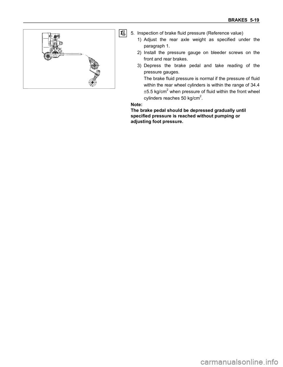
5. Inspection of brake fluid pressure (Reference value)
1) Adjust the rear axle weight as specified under the
paragraph 1.
2) Install the pressure gauge on bleeder screws on the
front and rear brakes.
3) Depress the brake pedal and take reading of the
pressure gauges.
The brake fluid pressure is normal if the pressure of fluid
within the rear wheel cylinders is within the range of 34.4
5.5 kg/cm2 when pressure of fluid within the front wheel
cylinders reaches 50 kg/cm2.
Note:
The brake pedal should be depressed gradually until
specified pressure is reached without pumping or
adjusting foot pressure.
Page 394 of 1600
5-66 BRAKES
Important Operations - Removal
Preparation
Raise vehicle to the working level.
Support the axle assembly with the proper jack and chassis
stands.
Remove the tire and wheel.
Remove the brake drum.
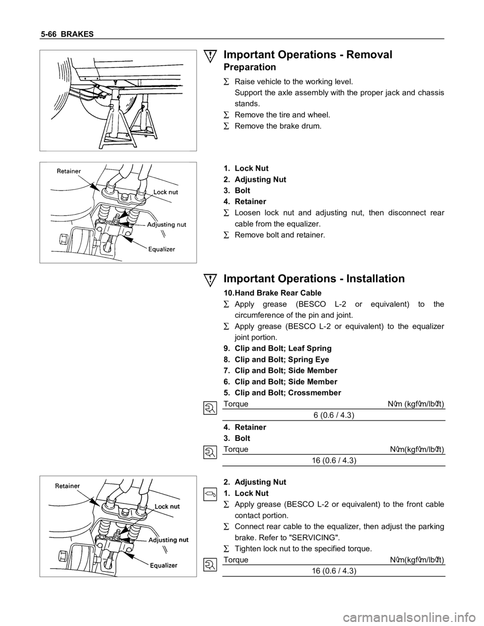
1. Lock Nut
2. Adjusting Nut
3. Bolt
4. Retainer
Loosen lock nut and adjusting nut, then disconnect rear
cable from the equalizer.
Remove bolt and retainer.
Important Operations - Installation
10.Hand Brake Rear Cable
Apply grease (BESCO L-2 or equivalent) to the
circumference of the pin and joint.
Apply grease (BESCO L-2 or equivalent) to the equalizer
joint portion.
9. Clip and Bolt; Leaf Spring
8. Clip and Bolt; Spring Eye
7. Clip and Bolt; Side Member
6. Clip and Bolt; Side Member
5. Clip and Bolt; Crossmember
Torque N
m (kgfm/lbft)
6 (0.6 / 4.3)
4. Retainer
3. Bolt
Torque N
m(kgfm/lbft)
16 (0.6 / 4.3)
2. Adjusting Nut
1. Lock Nut
Apply grease (BESCO L-2 or equivalent) to the front cable
contact portion.
Connect rear cable to the equalizer, then adjust the parking
brake. Refer to "SERVICING".
Tighten lock nut to the specified torque.
Torque N
m(kgfm/lbft)
16 (0.6 / 4.3)