Front axle ISUZU TFS SERIES 1997 User Guide
[x] Cancel search | Manufacturer: ISUZU, Model Year: 1997, Model line: TFS SERIES, Model: ISUZU TFS SERIES 1997Pages: 1600, PDF Size: 40.98 MB
Page 82 of 1600

FRONT WHEEL DRIVE 4C1-19
REASSEMBLY
Reassembly Steps
1. Axle case and differential
2. DOJ case
3. Bracket
4. Oil seal
5. O-ring
6. Snap ring
7. Bearing
8. Snap ring
9. DOJ case assembly
10. Bolt
11. BJ shaft12. Dust seal
13. Bellows
14. Band
15. Ball guide
16. Ball retainer
17. Snap ring
18. Ball
19. BJ shaft assembly
20. Circlip
21. Bellows
22. Band
Page 85 of 1600

4C1-22 FRONT WHEEL DRIVE
DIFFERENTIAL
DISASSEMBLY
MAJOR COMPONENTS
Disassembly Steps
1. Bolt
2. Differential assembly
3. Axle case
4. Bolt
5. Bearing cap
6. Diff. cage assembly
7. Side bearing outer race
8. Side bearing
9. Adjust shims
10. Flange nut
11. Flange12. Dust cover
13. Pinion gear
14. Inner bearing
15. Adjust shim
16. Collapsible spacer
17. Inner bearing outer race
18. Oil seal
19. Outer bearing
20. Outer bearing outer race
21. Diff. carrier
Page 91 of 1600

4C1-28 FRONT WHEEL DRIVE
Clearance Between the Side Gear and the
Differential Box
mm(in)
Standard Limit
167 mm 0.03 - 0.11 (0.001 - 0.004) 0.15 (0.006)
194 mm 0.03 - 0.10 (0.001 - 0.004) 0.15 (0.006)
Play in Splines Between the Side Gear
and the Axle Shaft
mm(in)
Standard Limit
167 mm 0.11 - 0.38 (0.004 - 0.015) 0.30 (0.012)
194 mm 0.07 - 0.36 (0.003 - 0.014) 0.25 (0.010)
Page 94 of 1600

FRONT WHEEL DRIVE 4C1-31
MAJOR COMPONENTS
Reassembly Steps
1. Diff. carrier
2. Outer bearing outer race
3. Inner bearing outer race
4. Adjust shim
5. Inner bearing
6. Collapsible spacer
7. Pinion gear
8. Outer bearing
9. Oil seal
10. Dust cover11. Flange
12. Flange nut and washer
13. Adjust shim
14. Side bearing
15. Bearing outer race
16. Diff. cage assembly
17. Bearing cap
18. Bolt
19. Axle case
20. Differential assembly
21. Bolt
Page 99 of 1600
4C1-36 FRONT WHEEL DRIVE
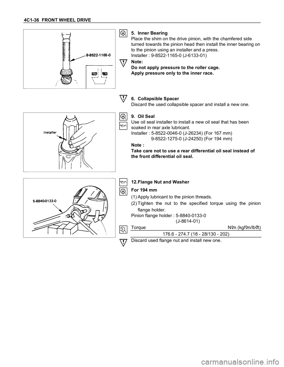
5. Inner Bearing
Place the shim on the drive pinion, with the chamfered side
turned towards the pinion head then install the inner bearing on
to the pinion using an installer and a press.
Installer : 9-8522-1165-0 (J-6133-01)
Note:
Do not apply pressure to the roller cage.
Apply pressure only to the inner race.
6. Collapsible Spacer
Discard the used collapsible spacer and install a new one.
9. Oil Seal
Use oil seal installer to install a new oil seal that has been
soaked in rear axle lubricant.
Installer : 5-8522-0046-0 (J-26234) (For 167 mm)
9-8522-1275-0 (J-24250) (For 194 mm)
Note :
Take care not to use a rear differential oil seal instead of
the front differential oil seal.
12.Flange Nut and Washer
For 194 mm
(1) Apply lubricant to the pinion threads.
(2) Tighten the nut to the specified torque using the pinion
flange holder.
Pinion flange holder : 5-8840-0133-0
(J-8614-01)
Torque N
m (kgfm/lbft)
176.6 - 274.7 (18 - 28/130 - 202)
Discard used flange nut and install new one.
Page 103 of 1600

4C1-40 FRONT WHEEL DRIVE
20.Differential Assembly
(1) Clean the faces of the front axle case and differential
carrier.
Apply the recommended liquid gasket or its equivalent to
the sealing side of the axle case and the carrier.
(2) Attach the differential case and the carrier assembly to the
front axle case and tighten the nuts and bolts. The axle
case bolt is used for drainage.
Torque N
m (kgfm/lbft)
25.5
5 (2.6 0.5/18.8 3.6)
(3) Install the axle shaft assemblies as instructed earlier in this
section under “Axle Shaft Replacement”.
(4) Fill the axle case with hypoid gear lubricant, to just below
the filler hole.
Lubricant capacity liter (US/UK gal)
167 mm 1.0 (0.26/0.22)
194 mm 1.4 (0.37/0.31)
Page 125 of 1600
4C1-62 FRONT WHEEL DRIVE
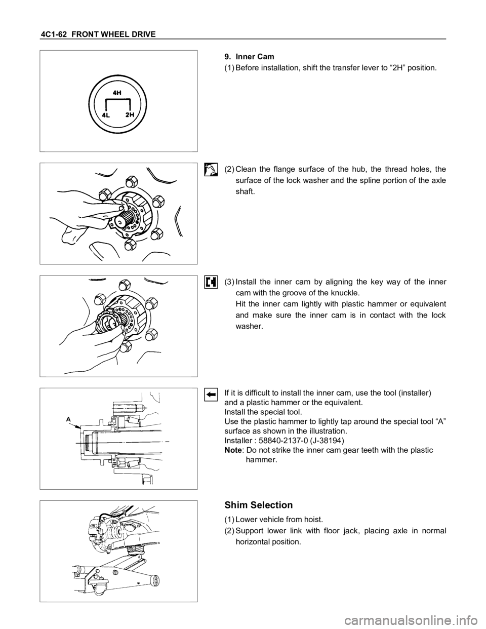
9. Inner Cam
(1) Before installation, shift the transfer lever to “2H” position.
(2) Clean the flange surface of the hub, the thread holes, the
surface of the lock washer and the spline portion of the axle
shaft.
(3) Install the inner cam by aligning the key way of the inner
cam with the groove of the knuckle.
Hit the inner cam lightly with plastic hammer or equivalent
and make sure the inner cam is in contact with the lock
washer.
If it is difficult to install the inner cam, use the tool (installer)
and a plastic hammer or the equivalent.
Install the special tool.
Use the plastic hammer to lightly tap around the special tool “A”
surface as shown in the illustration.
Installer : 58840-2137-0 (J-38194)
Note: Do not strike the inner cam gear teeth with the plastic
hammer.
Shim Selection
(1) Lower vehicle from hoist.
(2) Support lower link with floor jack, placing axle in normal
horizontal position.
Page 126 of 1600

FRONT WHEEL DRIVE 4C1-63
(3) Install special tool 5-8840-2126-0 to axle shaft by 5-8840-
2125-0 until it comes into contact with the lock washer.
(4) Using feeler gauge, measure clearance “t” between the
special tool and the snap ring groove of the axle shaft.
(5) If clearance “t” is larger than snap ring groove, shims must
be installed select shims so that clearance “t” is 0 to 0.1 mm
(0 to 0.0039 in).
Thickness shims; 0.2, 0.3, 0.5, 1.0 mm
(6) Remove special tool 5-8840-2126-0, leaving the inner cam
in position.
10.Drive Clutch Assembly
Apply multipurpose grease or hub bearing grease to the
following portions.
(1) Axle shaft splines
Page 127 of 1600

4C1-64 FRONT WHEEL DRIVE
“A” groove and “B” portion
g(oz)
“A” Groove 7 (0.25)
“B” portion 3 (0.11)
“C” circumference and “D” portion
g(oz)
“C” circumference 8 (0.29)
“D” portion 4 (0.15)
(2) Align the cut part of the drive clutch assembly with the
protudent part of inner cam.
(3) Engage the cam teeth of the drive clutch assembly to that of
the inner cam by turning the axle shaft.
11.Snap Ring and Shims
(1) Install shims (selected above) to axle by hand.
Note :
Always use a new snap ring.
(2) Install special tool 5-8840-2125-0 (B) to axle.
(3) Install snap ring to tool.
(4) Install tool driver 5-8840-2125-0 (A).
(5) Pull out the axle shaft fully by pulling the tool 5-8840-2125-0
(B) and install snap ring to axle by pushing on tool driver 5-
8840-2125-0 (A).
(6) Remove tool from axle.
Snap ring installer : 5-8840-2125-0
(J-36835)
Page 140 of 1600

FRONT WHEEL DRIVE 4C1-77
INSPECTION AND REPAIR
Make necessary correction or parts replacement if wear, damage or any other abnormal conditions are found
through inspection.
Spider
Needle roller bearing
Yoke
Flange
Center bearing
Cushioning rubber
Bracket
Visual Check
Check the following parts for wear, damage or other abnormal
conditions.
Outside Diameter of Spider Pins
TF Side for Type - A and B mm(in)
Standard Limit
17.000 (0.669) 16.90 (0.665)
Axle Side for Type - A mm(in)
Standard Limit
14.724 (0.580) 14.624 (0.576)
Play in Splines in Normal Direction of
Rotation
Check the amount of play in the sleeve yoke and propeller
shaft splines in the direction of rotation, using a pointed feeler
gauge.
mm(in)
Standard Limit
0.074 - 0.156
(0.003 - 0.006)0.3 (0.012)