ISUZU TFS SERIES 1997 Owner's Manual
TFS SERIES 1997
ISUZU
ISUZU
https://www.carmanualsonline.info/img/61/57182/w960_57182-0.png
ISUZU TFS SERIES 1997 Owner's Manual
Page 76 of 1600
FRONT WHEEL DRIVE 4C1-13
Important Operations - Removal
1. Assembly of hub and disc, back plate, knuckle, knuckle
arm, and lower end.
Before removal, jack up the front of vehicle and support the
frame with jack stands.
2. Propeller Shaft
Apply the setting marks.
5. Front Drive Axle Assembly
(1) Put the lifting jack under the center part of the front.
(2) Remove four bolts fixing axle case mounting brackets to the
frame.
Note :
Be careful not to damage birfield joints or double off-set
joints when supporting axle shaft assembly.
(3) Lower the front axle assembly and roll it out toward the front
of the vehicle.
Take care not to damage the birfield joints or the double off-
set joints.
Page 77 of 1600
4C1-14 FRONT WHEEL DRIVE
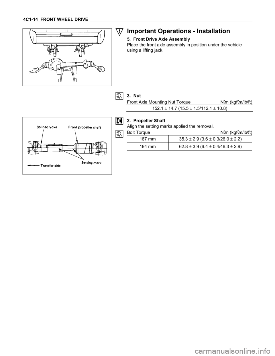
Important Operations - Installation
5. Front Drive Axle Assembly
Place the front axle assembly in position under the vehicle
using a lifting jack.
3. Nut
Front Axle Mounting Nut Torque N
m (kgfm/lbft)
152.1
14.7 (15.5 1.5/112.1 10.8)
2. Propeller Shaft
Align the setting marks applied the removal.
Bolt Torque N
m (kgfm/lbft)
167 mm 35.3
2.9 (3.6 0.3/26.0 2.2)
194 mm 62.8 3.9 (6.4 0.4/46.3 2.9)
Page 78 of 1600
FRONT WHEEL DRIVE 4C1-15
DISASSEMBLY
Disassembly Steps
1. Band
2. Bellows
3. Circlip
4. BJ shaft assembly
5. Ball
6. Snap ring
7. Ball retainer
8. Ball guide
9. Band
10. Bellows
11. Dust seal12. BJ shaft
13. Bolt
14. DOJ case assembly
15. Snap ring
16. Bearing
17. Snap ring
18. O-ring
19. Oil seal
20. Bracket
21. DOJ case
22. Axle case and differential
Page 79 of 1600
4C1-16 FRONT WHEEL DRIVE
Important Operations
1. Band
Raise the hooked end of the band with a screwdriver or
equivalent.
3. Circlip
Pry off with a screwdriver or equivalent.
5. Ball
Remove the six balls with a screwdriver or equivalent.
Rotate the case half a pitch to align the ball guide on the case
with the projected portion of the ball retainer, then slide the
case toward the bellows. The case can not be removed in the
reverse direction.
6. Snap Ring
Remove the snap ring fastening the ball retainer to the center
shaft.
Page 80 of 1600
FRONT WHEEL DRIVE 4C1-17
8. Band
Raise the hooked end of the band with a screwdriver or
equivalent.
Page 81 of 1600
4C1-18 FRONT WHEEL DRIVE
INSPECTION AND REPAIR
Make all necessary adjustments, repairs, and part replacements if wear, damage, or other problems are discovered
during inspection.
BJ assembly
DOJ case, ball, ball guide, ball retainer
Bellows
Bearing
Dust seal, oil seal
Visual Check
Inspect the following parts for wear, damage, or other
abnormal conditions.
Page 82 of 1600
FRONT WHEEL DRIVE 4C1-19
REASSEMBLY
Reassembly Steps
1. Axle case and differential
2. DOJ case
3. Bracket
4. Oil seal
5. O-ring
6. Snap ring
7. Bearing
8. Snap ring
9. DOJ case assembly
10. Bolt
11. BJ shaft12. Dust seal
13. Bellows
14. Band
15. Ball guide
16. Ball retainer
17. Snap ring
18. Ball
19. BJ shaft assembly
20. Circlip
21. Bellows
22. Band
Page 83 of 1600
4C1-20 FRONT WHEEL DRIVE
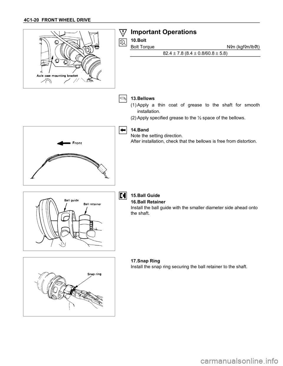
Important Operations
10.Bolt
Bolt Torque N
m (kgfm/lbft)
82.4
7.8 (8.4 0.8/60.8 5.8)
13.Bellows
(1) Apply a thin coat of grease to the shaft for smooth
installation.
(2) Apply specified grease to the ½ space of the bellows.
14.Band
Note the setting direction.
After installation, check that the bellows is free from distortion.
15.Ball Guide
16.Ball Retainer
Install the ball guide with the smaller diameter side ahead onto
the shaft.
17.Snap Ring
Install the snap ring securing the ball retainer to the shaft.
Page 84 of 1600
FRONT WHEEL DRIVE 4C1-21
18.Ball
Bring the ball guide of the cage into alignment with the
projected portion of the ring on the ball retainer, then turn the
cage ½ pitch. Align the track on the ball retainer with the
window in the cage and install the six balls into position.
19.BJ Shaft Assembly
Apply specified grease to the half of the space of the DOJ case
(Approx. 50g (1.8 oz)).
20.Circlip
Install the circlip so that open ends are positioned away from
the ball groove.
21.Bellows
(1) Before installation, insert the appropriate amount of
specified grease into the DOJ case.
(2) Adjust the air pressure within the bellows by inserting a
screwdriver or equivalent, so that it equals atmospheric
pressure.
22.Band
After installation, check that the bellows is free from distortion.
Page 85 of 1600
4C1-22 FRONT WHEEL DRIVE
DIFFERENTIAL
DISASSEMBLY
MAJOR COMPONENTS
Disassembly Steps
1. Bolt
2. Differential assembly
3. Axle case
4. Bolt
5. Bearing cap
6. Diff. cage assembly
7. Side bearing outer race
8. Side bearing
9. Adjust shims
10. Flange nut
11. Flange12. Dust cover
13. Pinion gear
14. Inner bearing
15. Adjust shim
16. Collapsible spacer
17. Inner bearing outer race
18. Oil seal
19. Outer bearing
20. Outer bearing outer race
21. Diff. carrier


