ad blue ISUZU TFS SERIES 1997 Workshop Manual
[x] Cancel search | Manufacturer: ISUZU, Model Year: 1997, Model line: TFS SERIES, Model: ISUZU TFS SERIES 1997Pages: 1600, PDF Size: 40.98 MB
Page 1 of 1600

REAR AXLE 4B-5
RECOMMENDED LIQUID GASKET
Type Brand Name Manufacture Remarks
RTV*
Silicon BaseThreeBond 1207B
ThreeBond 1207C
ThreeBond 1215Three Bond
Three Bond
Three BondFor Engine Repairs
For Axle Case
Repairs, T/M
Water Base ThreeBond 1141E Three Bond For Engine Repairs
SolventThreeBond 1104
BelcoBond 4
BelcoBond 401
BelcoBond 402Three bond
Isuzu
Isuzu
IsuzuFor Engine Repairs
AnerobicLOCTITE 515
LOCTITE 518Loctite
LoctiteAll
* RTV : Room Temperature Vulcanizer
Note :
1. It is very important that the liquid gaskets listed above or their exact equivalent be used on the vehicle.
2. Be careful to use the specified amount of liquid gasket.
Follow the manufacture's instructions at all times.
3. Be absolutely sure to remove all lubricants and moisture from the connecting surfaces before applying
the liquid gasket.
The connecting surfaces must be perfectly dry.
4. LOCTITE 515 and LOCTITE 518 harden upon contact with a metal surface.
Do not apply LOCTITE 515 or LOCTITE 518 between two metal surfaces having a clearance of greater
than 0.25 mm (0.01 in). Poor adhesion will result.
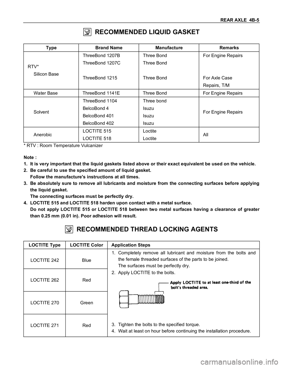
RECOMMENDED THREAD LOCKING AGENTS
LOCTITE Type LOCTITE Color Application Steps
LOCTITE 242 Blue1. Completely remove all lubricant and moisture from the bolts and
the female threaded surfaces of the parts to be joined.
The surfaces must be perfectly dry.
LOCTITE 262 Red2. Apply LOCTITE to the bolts.
LOCTITE 270 Green
LOCTITE 271 Red3. Tighten the bolts to the specified torque.
4. Wait at least on hour before continuing the installation procedure.
Page 46 of 1600

4B-50 REAR AXLE
16.Bolt
Cap Bolt Torque N
m (kgfm/lbft)
194 mm 98.1
9.8 (10 1/72 7.2)
220 mm 107.9 9.8 (11 1/79.5 7.2)
Measure the amount of run-out of the ring gear at its rear face.
Run-Out mm(in)
Standard Limit
194 mm
220 mm0.02 (0.001) 0.05 (0.002)
Gear Tooth Contact Pattern Check and
Adjustment
Apply a thin coat of prussian blue or equivalent to the faces of
7 - 8 teeth of the ring gear. Check the impression of contact
obtained on the ring gear teeth and make necessary
adjustment as described below if the contact is abnormal.
Page 70 of 1600

FRONT WHEEL DRIVE 4C1-7
RECOMMENDED LIQUID GASKET
Type Brand Name Manufacture Remarks
RTV*
Silicon BaseThreeBond 1207B
ThreeBond 1207C
ThreeBond 1215Three Bond
Three Bond
Three BondFor Engine Repairs
For Axle Case
Repairs, T/M
Water Base ThreeBond 1141E Three Bond For Engine Repairs
SolventThreeBond 1104
BelcoBond 4
BelcoBond 401
BelcoBond 402Three bond
Isuzu
Isuzu
IsuzuFor Engine Repairs
AnerobicLOCTITE 515
LOCTITE 518Loctite
LoctiteAll
* RTV : Room Temperature Vulcanizer
Note :
1. It is very important that the liquid gaskets listed above or their exact equivalent be used on the vehicle.
2. Be careful to use the specified amount of liquid gasket.
Follow the manufacture's instructions at all times.
3. Be absolutely sure to remove all lubricants and moisture from the connecting surfaces before applying
the liquid gasket.
The connecting surfaces must be perfectly dry.
4. LOCTITE 515 and LOCTITE 518 harden upon contact with a metal surface.
Do not apply LOCTITE 515 or LOCTITE 518 between two metal surfaces having a clearance of greater
than 0.25 mm (0.01 in). Poor adhesion will result.
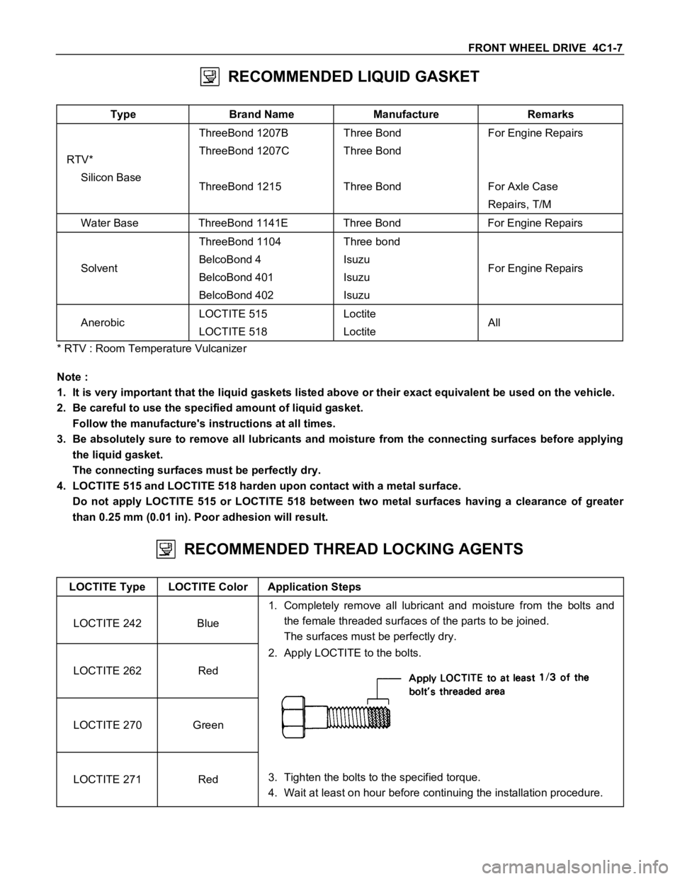
RECOMMENDED THREAD LOCKING AGENTS
LOCTITE Type LOCTITE Color Application Steps
LOCTITE 242 Blue1. Completely remove all lubricant and moisture from the bolts and
the female threaded surfaces of the parts to be joined.
The surfaces must be perfectly dry.
LOCTITE 262 Red2. Apply LOCTITE to the bolts.
LOCTITE 270 Green
LOCTITE 271 Red3. Tighten the bolts to the specified torque.
4. Wait at least on hour before continuing the installation procedure.
Page 102 of 1600

FRONT WHEEL DRIVE 4C1-39
17.Bearing Cap
Align the setting marks applied at disassembly.
18.Bolt
Bolt Torque N
m (kgfm/lbft)
167 mm 68.7
9.8 (7.0 1.0/50.6 7.2)
194 mm 98.1 9.8 (10.0 1.0/72.3 7.2)
Measure the amount of run-out of the ring gear at its rear face.
mm(in)
Standard Limit
0.02 (0.001) 0.05 (0.002)
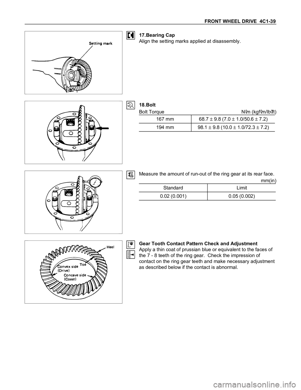
Gear Tooth Contact Pattern Check and Adjustment
Apply a thin coat of prussian blue or equivalent to the faces of
the 7 - 8 teeth of the ring gear. Check the impression of
contact on the ring gear teeth and make necessary adjustment
as described below if the contact is abnormal.
Page 142 of 1600

FRONT WHEEL DRIVE 4C1-79
(4) Align setting marks (1) and join the yokes.
(5) Install snap ring.
NOTE:
Discard used snap rings and install new ones.
When the bearing cap is in position, select and attach a snap
ring of suitable thickness so that the end play of the spider pin
is held within 0.1mm (0.004 in).
T/F side for Type - A and B
Snap ring thickness and Identification color
1.5mm (0.059 in); Blue
1.53mm (0.060 in); White
1.59mm (0.063 in); Yellow
1.62mm (0.064 in); Green
1.68mm (0.066 in); Not colored
Axle side for Type - A
1.44mm (0.057 in); Not colored
1.49mm (0.059 in); Not colored
1.54mm (0.061 in); Not colored
NOTE:
Be sure to use snap rings of the same thickness on both sides.