oil ISUZU TFS SERIES 1997 Workshop Manual
[x] Cancel search | Manufacturer: ISUZU, Model Year: 1997, Model line: TFS SERIES, Model: ISUZU TFS SERIES 1997Pages: 1600, PDF Size: 40.98 MB
Page 3 of 1600
REAR AXLE 4B-7
SERVICING
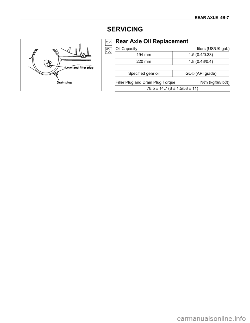
Rear Axle Oil Replacement
Oil Capacity liters (US/UK gal.)
194 mm 1.5 (0.4/0.33)
220 mm 1.8 (0.48/0.4)
Specified gear oil GL-5 (API grade)
Filler Plug and Drain Plug Torque Nm (kgfm/lbft)
78.5
14.7 (8 1.5/58 11)
Page 4 of 1600
4B-8 REAR AXLE
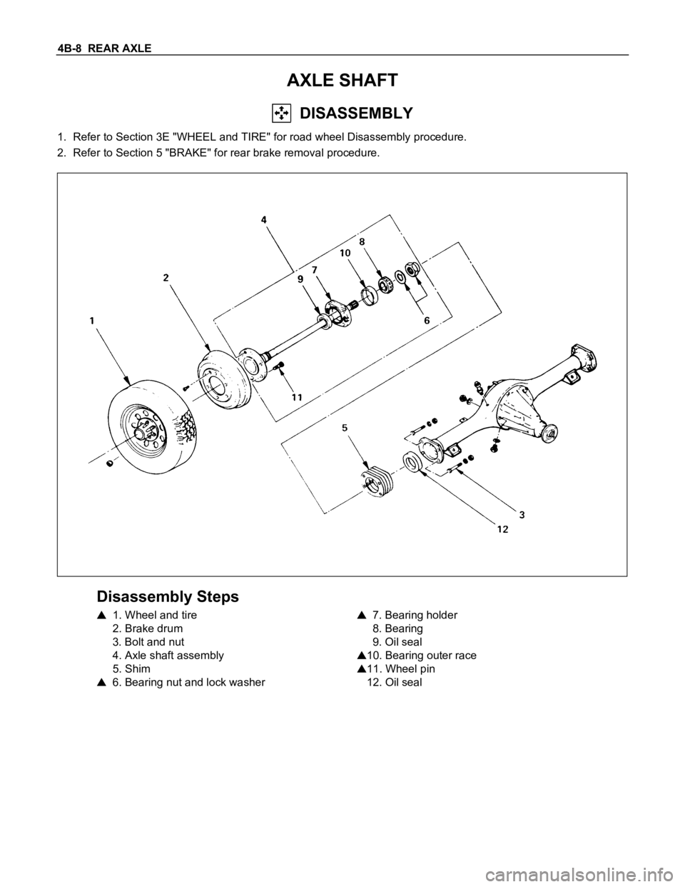
AXLE SHAFT
DISASSEMBLY
1. Refer to Section 3E "WHEEL and TIRE" for road wheel Disassembly procedure.
2. Refer to Section 5 "BRAKE" for rear brake removal procedure.
Disassembly Steps
1. Wheel and tire
2. Brake drum
3. Bolt and nut
4. Axle shaft assembly
5. Shim
6. Bearing nut and lock washer
7. Bearing holder
8. Bearing
9. Oil seal
10. Bearing outer race
11. Wheel pin
12. Oil seal
Page 8 of 1600
4B-12 REAR AXLE
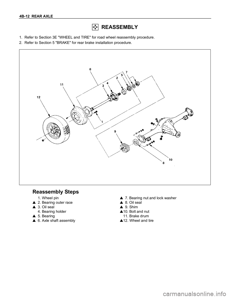
REASSEMBLY
1. Refer to Section 3E "WHEEL and TIRE" for road wheel reassembly procedure.
2. Refer to Section 5 "BRAKE" for rear brake installation procedure.
Reassembly Steps
1. Wheel pin
2. Bearing outer race
3. Oil seal
4. Bearing holder
5. Bearing
6. Axle shaft assembly
7. Bearing nut and lock washer
8. Oil seal
9. Shim
10. Bolt and nut
11. Brake drum
12. Wheel and tire
Page 9 of 1600
REAR AXLE 4B-13
Important Operations
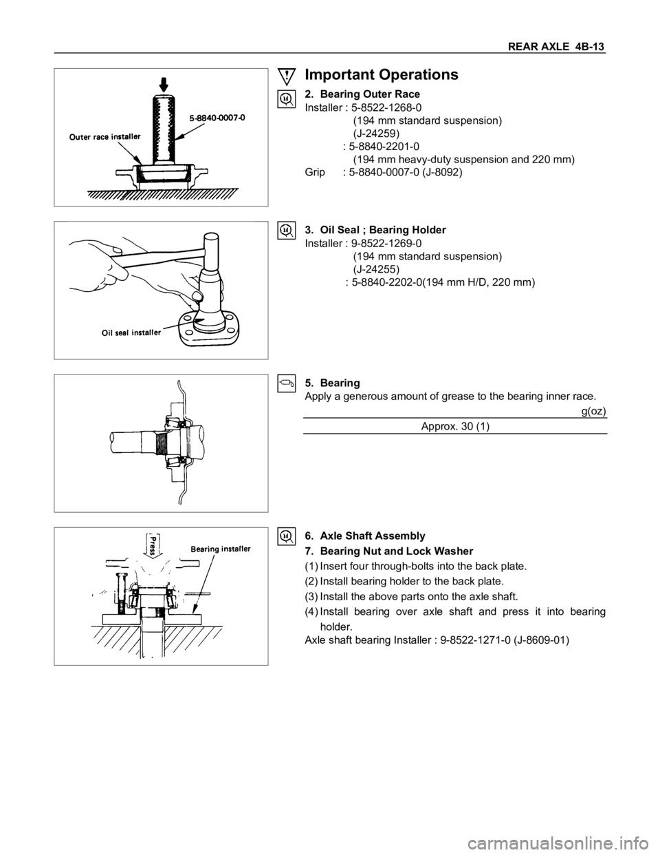
2. Bearing Outer Race
Installer : 5-8522-1268-0
(194 mm standard suspension)
(J-24259)
: 5-8840-2201-0
(194 mm heavy-duty suspension and 220 mm)
Grip : 5-8840-0007-0 (J-8092)
3. Oil Seal ; Bearing Holder
Installer : 9-8522-1269-0
(194 mm standard suspension)
(J-24255)
: 5-8840-2202-0(194 mm H/D, 220 mm)
5. Bearing
Apply a generous amount of grease to the bearing inner race.
g(oz)
Approx. 30 (1)
6. Axle Shaft Assembly
7. Bearing Nut and Lock Washer
(1) Insert four through-bolts into the back plate.
(2) Install bearing holder to the back plate.
(3) Install the above parts onto the axle shaft.
(4) Install bearing over axle shaft and press it into bearing
holder.
Axle shaft bearing Installer : 9-8522-1271-0 (J-8609-01)
Page 10 of 1600
4B-14 REAR AXLE
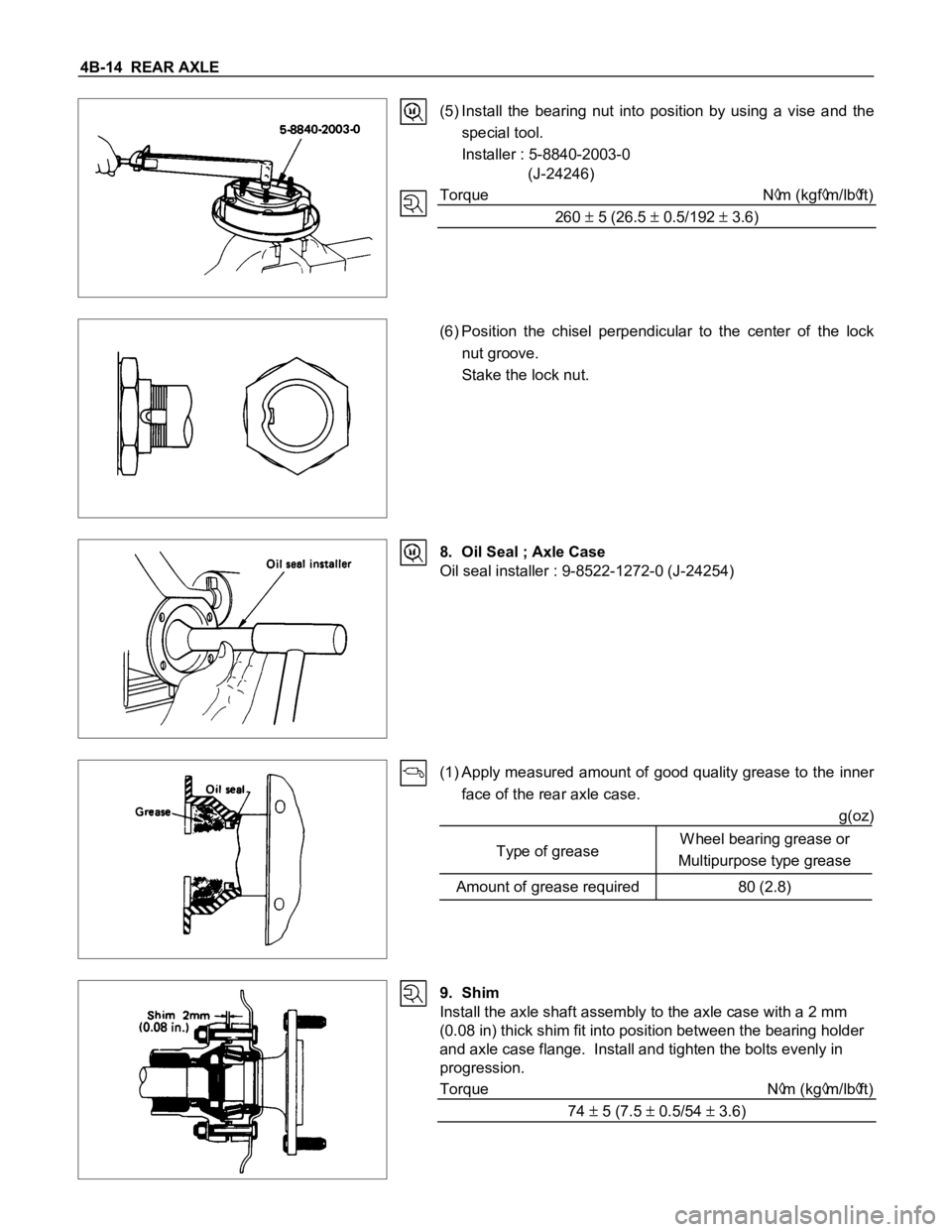
(5) Install the bearing nut into position by using a vise and the
special tool.
Installer : 5-8840-2003-0
(J-24246)
Torque N
m (kgfm/lbft)
260
5 (26.5 0.5/192 3.6)
(6) Position the chisel perpendicular to the center of the lock
nut groove.
Stake the lock nut.
8. Oil Seal ; Axle Case
Oil seal installer : 9-8522-1272-0 (J-24254)
(1) Apply measured amount of good quality grease to the inner
face of the rear axle case.
g(oz)
Type of greaseW heel bearing grease or
Multipurpose type grease
Amount of grease required 80 (2.8)
9. Shim
Install the axle shaft assembly to the axle case with a 2 mm
(0.08 in) thick shim fit into position between the bearing holder
and axle case flange. Install and tighten the bolts evenly in
progression.
Torque N
m (kgm/lbft)
74
5 (7.5 0.5/54 3.6)
Page 14 of 1600

4B-18 REAR AXLE
DISASSEMBLY
MAJOR COMPONENTS
Disassembly Steps
1. Side bearing cap
2. Side bearing outer race
3. Differential cage assembly and ring gear
4. Side bearing
5. Backlash and side bearing preload
adjusting shim
6. Flange nut and washer
7. Flange assembly
8. Drive pinion shaft assembly
9. Inner bearing
10. Pinion depth adjusting shim
11. Drive pinion shaft
12. Collapsible spacer
13. Oil seal
14. Outer bearing
15. Inner bearing outer race
16. Outer bearing outer race
Page 24 of 1600

4B-28 REAR AXLE
Differential cage
Check the ring gear the side gear fitting faces and the cross pin
hole for scores or roughness. Correct as necessary. Slight
scores or roughness may be corrected with an oil stone or fine
sand paper.
Friction disc and plate assembly.
Check the parts for damage or other abnormal conditions.
Check the friction plate for distortion.
Limit mm(in) 0.07 (0.0027)
Check the friction plate for wear.
Limit (A - B) mm(in) 0.1 (0.0039)
Note : A = Non-sliding face thickness
B = Sliding face thickness
Check the friction disc for distortion.
Limit mm(in) 0.07 (0.0027)
Page 38 of 1600
4B-42 REAR AXLE
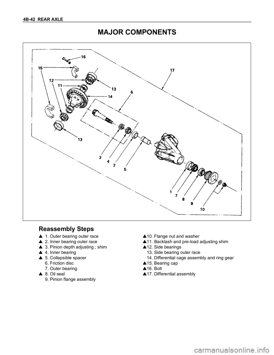
MAJOR COMPONENTS
Reassembly Steps
1. Outer bearing outer race
2. Inner bearing outer race
3. Pinion depth adjusting ; shim
4. Inner bearing
5. Collapsible spacer
6. Friction disc
7. Outer bearing
8. Oil seal
9. Pinion flange assembly
10. Flange nut and washer
11. Backlash and pre-load adjusting shim
12. Side bearings
13. Side bearing outer race
14. Differential cage assembly and ring gear
15. Bearing cap
16. Bolt
17. Differential assembly
Page 39 of 1600
REAR AXLE 4B-43
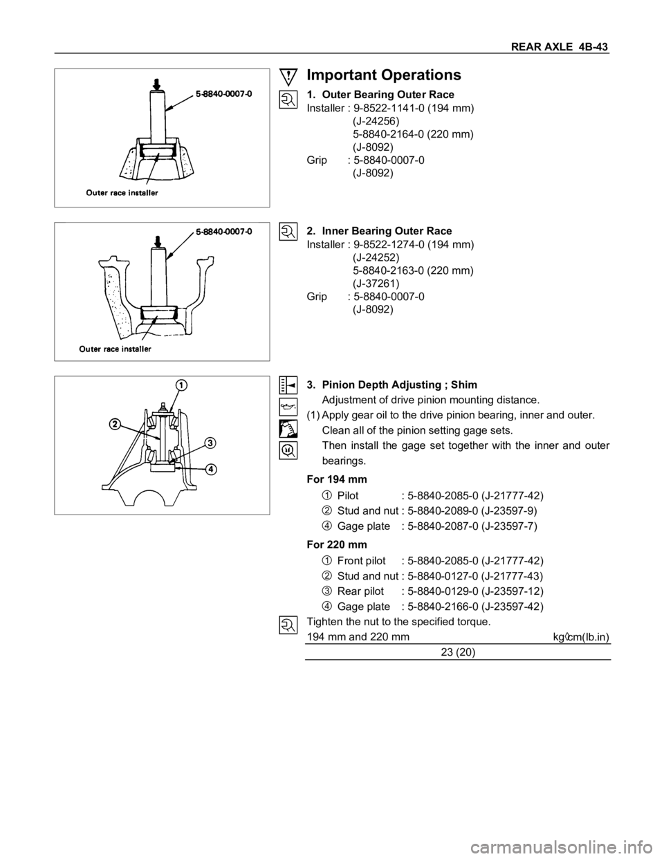
Important Operations
1. Outer Bearing Outer Race
Installer : 9-8522-1141-0 (194 mm)
(J-24256)
5-8840-2164-0 (220 mm)
(J-8092)
Grip : 5-8840-0007-0
(J-8092)
2. Inner Bearing Outer Race
Installer : 9-8522-1274-0 (194 mm)
(J-24252)
5-8840-2163-0 (220 mm)
(J-37261)
Grip : 5-8840-0007-0
(J-8092)
3. Pinion Depth Adjusting ; Shim
Adjustment of drive pinion mounting distance.
(1) Apply gear oil to the drive pinion bearing, inner and outer.
Clean all of the pinion setting gage sets.
Then install the gage set together with the inner and outer
bearings.
For 194 mm
1Pilot : 5-8840-2085-0 (J-21777-42)
2Stud and nut : 5-8840-2089-0 (J-23597-9)
4Gage plate : 5-8840-2087-0 (J-23597-7)
For 220 mm
1Front pilot : 5-8840-2085-0 (J-21777-42)
2Stud and nut : 5-8840-0127-0 (J-21777-43)
3Rear pilot : 5-8840-0129-0 (J-23597-12)
4Gage plate : 5-8840-2166-0 (J-23597-42)
Tighten the nut to the specified torque.
194 mm and 220 mm kg
cm(lb.in)
23 (20)
Page 43 of 1600

REAR AXLE 4B-47
4. Inner Bearing
Place the shim on the drive pinion with the chamfered side
turned toward the pinion head, then attach the inner bearing to
the pinion using an installer and a press.
Installer : 9-8522-1165-0
(J-6133-01)
NOTE :
Do not press on the roller cage.
Press only on the inner race.
5. Collapsible Spacer
Discard the used collapsible spacer and install a new one.
8. Oil Seal
Use the oil seal installer to install a new oil seal that has been
soaked in rear axle lubricant.
Installer : 9-8522-1275-0 (194 mm)
(J-24250)
: 5-8840-2165-0 (220 mm)
(J-37263)
10.Flange Nut and Washer
(1) Apply lubricant to pinion threads.
(2) Tighten the nut to the specified torque using the pinion
flange holder.
Pinion flange holder : 5-8840-0133-0 (194 mm)
(J-8614-01)
5-8840-2157-0 (220 mm)
(J-37221)
Flange Nut Torque N
m (kgfm/lbft)
194 mm 176.6 - 274.7 (18 - 28/130 - 202)
220 mm 245.3 - 294.3 (25 - 30/181 - 217)
Discard used flange nuts and install new ones.