light ISUZU TFS SERIES 1997 Workshop Manual
[x] Cancel search | Manufacturer: ISUZU, Model Year: 1997, Model line: TFS SERIES, Model: ISUZU TFS SERIES 1997Pages: 1600, PDF Size: 40.98 MB
Page 5 of 1600
REAR AXLE 4B-9
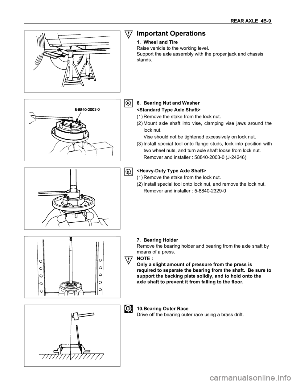
Important Operations
1. Wheel and Tire
Raise vehicle to the working level.
Support the axle assembly with the proper jack and chassis
stands.
6. Bearing Nut and Washer
(1) Remove the stake from the lock nut.
(2) Mount axle shaft into vise, clamping vise jaws around the
lock nut.
Vise should not be tightened excessively on lock nut.
(3) Install special tool onto flange studs, lock into position with
two wheel nuts, and turn axle shaft loose from lock nut.
Remover and installer : 58840-2003-0 (J-24246)
(1) Remove the stake from the lock nut.
(2) Install special tool onto lock nut, and remove the lock nut.
Remover and installer : 5-8840-2329-0
7. Bearing Holder
Remove the bearing holder and bearing from the axle shaft by
means of a press.
NOTE :
Only a slight amount of pressure from the press is
required to separate the bearing from the shaft. Be sure to
support the backing plate solidly, and to hold onto the
axle shaft to prevent it from falling to the floor.
10.Bearing Outer Race
Drive off the bearing outer race using a brass drift.
Page 7 of 1600
REAR AXLE 4B-11
INSPECTION AND REPAIR
Make all necessary adjustments, repairs, and part replacements if wear, damage, or other problems are discovered
during inspections.
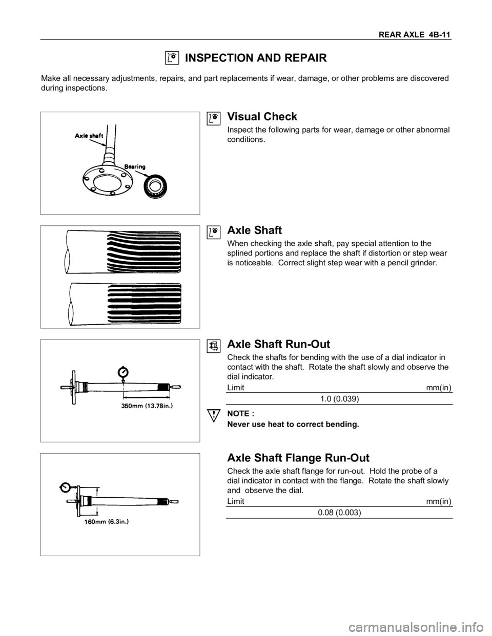
Visual Check
Inspect the following parts for wear, damage or other abnormal
conditions.
Axle Shaft
When checking the axle shaft, pay special attention to the
splined portions and replace the shaft if distortion or step wear
is noticeable. Correct slight step wear with a pencil grinder.
Axle Shaft Run-Out
Check the shafts for bending with the use of a dial indicator in
contact with the shaft. Rotate the shaft slowly and observe the
dial indicator.
Limit mm(in)
1.0 (0.039)
NOTE :
Never use heat to correct bending.
Axle Shaft Flange Run-Out
Check the axle shaft flange for run-out. Hold the probe of a
dial indicator in contact with the flange. Rotate the shaft slowly
and observe the dial.
Limit mm(in)
0.08 (0.003)
Page 24 of 1600

4B-28 REAR AXLE
Differential cage
Check the ring gear the side gear fitting faces and the cross pin
hole for scores or roughness. Correct as necessary. Slight
scores or roughness may be corrected with an oil stone or fine
sand paper.
Friction disc and plate assembly.
Check the parts for damage or other abnormal conditions.
Check the friction plate for distortion.
Limit mm(in) 0.07 (0.0027)
Check the friction plate for wear.
Limit (A - B) mm(in) 0.1 (0.0039)
Note : A = Non-sliding face thickness
B = Sliding face thickness
Check the friction disc for distortion.
Limit mm(in) 0.07 (0.0027)
Page 125 of 1600
4C1-62 FRONT WHEEL DRIVE
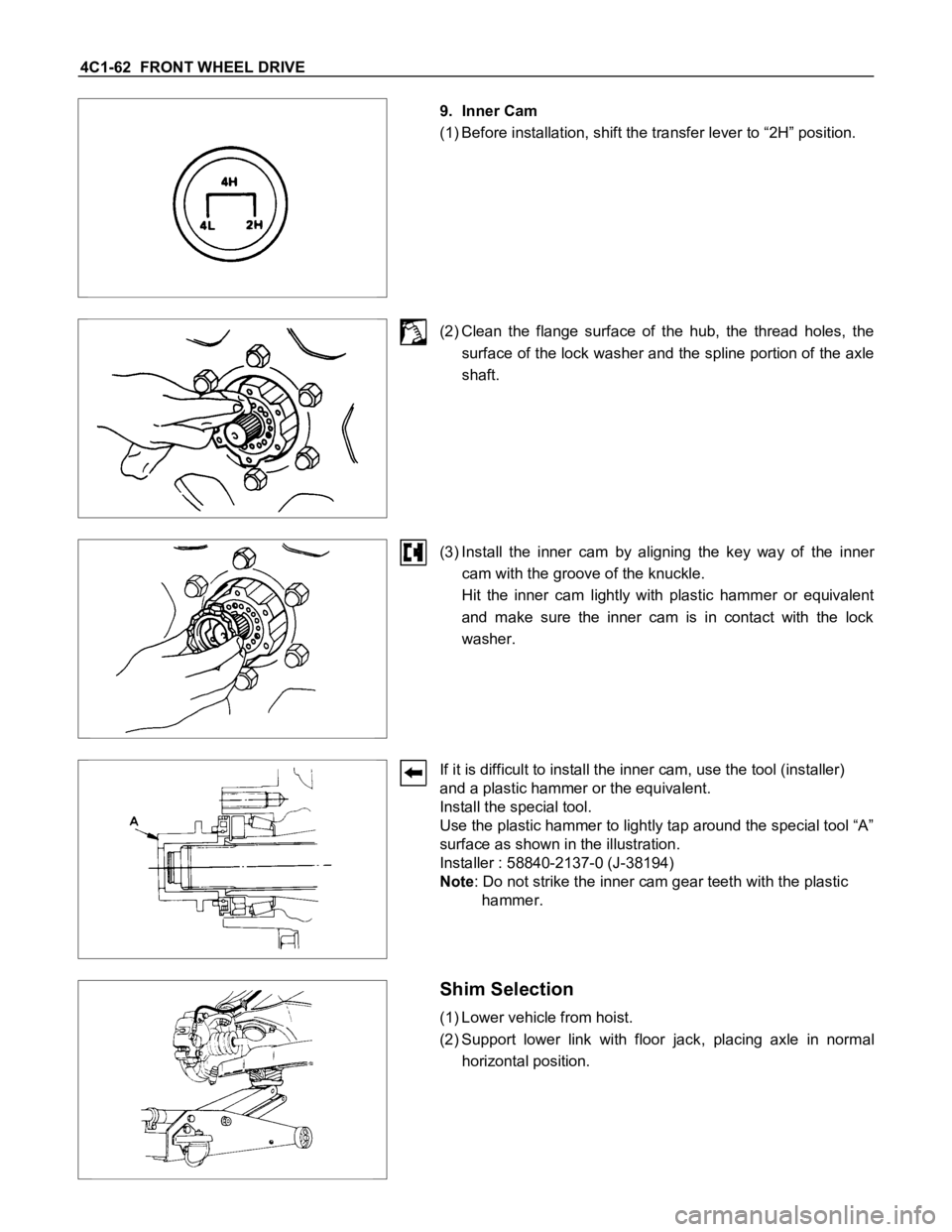
9. Inner Cam
(1) Before installation, shift the transfer lever to “2H” position.
(2) Clean the flange surface of the hub, the thread holes, the
surface of the lock washer and the spline portion of the axle
shaft.
(3) Install the inner cam by aligning the key way of the inner
cam with the groove of the knuckle.
Hit the inner cam lightly with plastic hammer or equivalent
and make sure the inner cam is in contact with the lock
washer.
If it is difficult to install the inner cam, use the tool (installer)
and a plastic hammer or the equivalent.
Install the special tool.
Use the plastic hammer to lightly tap around the special tool “A”
surface as shown in the illustration.
Installer : 58840-2137-0 (J-38194)
Note: Do not strike the inner cam gear teeth with the plastic
hammer.
Shim Selection
(1) Lower vehicle from hoist.
(2) Support lower link with floor jack, placing axle in normal
horizontal position.
Page 346 of 1600
5-18 BRAKES
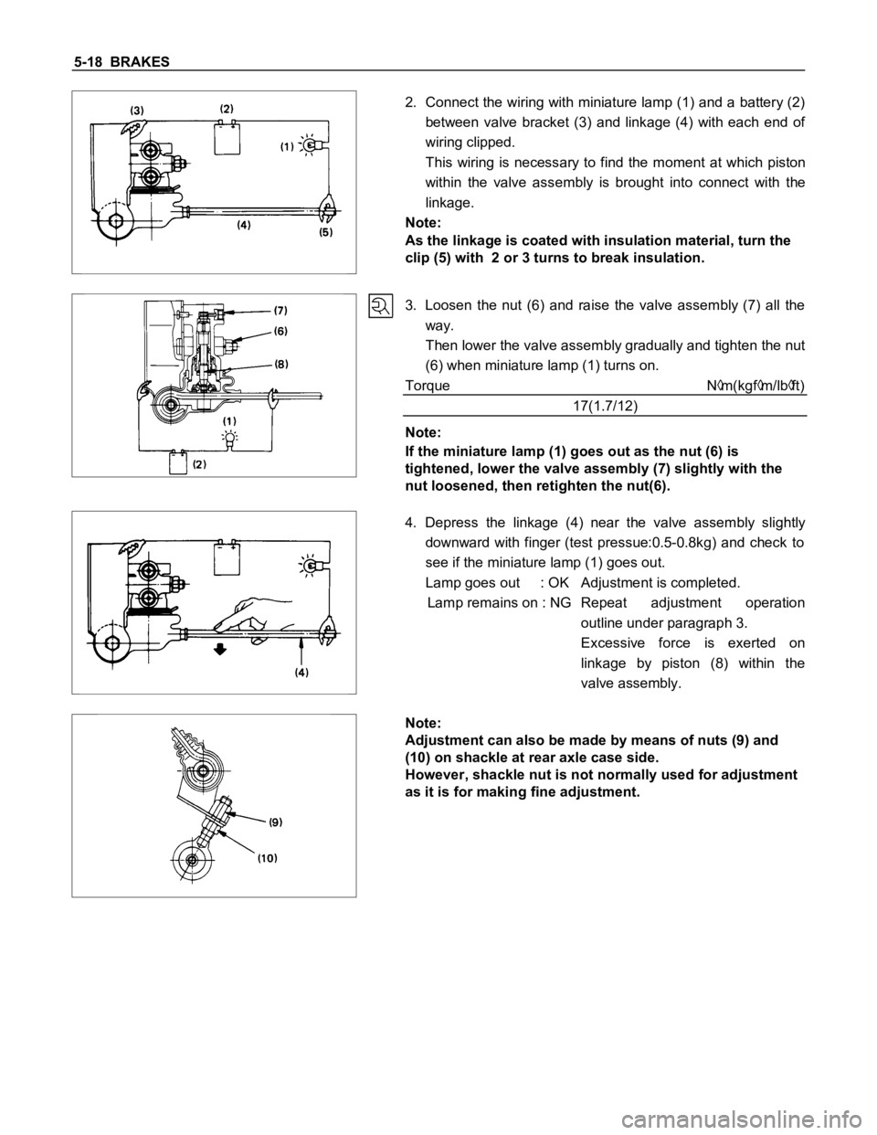
2. Connect the wiring with miniature lamp (1) and a battery (2)
between valve bracket (3) and linkage (4) with each end of
wiring clipped.
This wiring is necessary to find the moment at which piston
within the valve assembly is brought into connect with the
linkage.
Note:
As the linkage is coated with insulation material, turn the
clip (5) with 2 or 3 turns to break insulation.
3. Loosen the nut (6) and raise the valve assembly (7) all the
way.
Then lower the valve assembly gradually and tighten the nut
(6) when miniature lamp (1) turns on.
Torque N
m(kgfm/lbft)
17(1.7/12)
Note:
If the miniature lamp (1) goes out as the nut (6) is
tightened, lower the valve assembly (7) slightly with the
nut loosened, then retighten the nut(6).
4. Depress the linkage (4) near the valve assembly slightly
downward with finger (test pressue:0.5-0.8kg) and check to
see if the miniature lamp (1) goes out.
Lamp goes out : OK Adjustment is completed.
Lamp remains on : NG Repeat adjustment operation
outline under paragraph 3.
Excessive force is exerted on
linkage by piston (8) within the
valve assembly.
Note:
Adjustment can also be made by means of nuts (9) and
(10) on shackle at rear axle case side.
However, shackle nut is not normally used for adjustment
as it is for making fine adjustment.
Page 372 of 1600

5-44 BRAKES
18.Brake Line
Torque N
m(kgfm/Ibft)
13 - 19 (1.3 - 1.9 / 9 - 14)
Apply grease lightly to back plate A.
Page 387 of 1600

BRAKES 5-59
Important Operations - Removal
11.Cable Assembly ; Rear
When abrasion or wear is evident on edge protector, in must
be replaced with new one.
Important Operations - Installation
13.1st Relay Lever Assembly
Apply grease (BESCO L-2 or equivalent) to the inner and outer
surface of the bushes and cable connecting portions.
12.2nd Relay Lever Assembly with Return Spring
Apply grease (BESCO L-2 or equivalent) to the arrowed portion
in the left figure.
8. Intermediate Cable
After applying grease (BESCO L-2 or equivalent) to the cable
guide, set it to the bracket by striking lightly with a mallet.
Page 455 of 1600

CAB 10-1
SECTION 10
CAB
TABLE OF CONTENTS
PAGE
Servicing<0011001100110011001100110011001100110011001100110011001100110011001100110011001100110011001100110011001100110011001100110011001100110011001100110011001100110011001100110011001100110011001100110011001100
11001100110011[<0011001100110011001100110011001100110011001100110011001100110011001100110011001100110011001100110011001100110011001100110011001100110011001100110011001100110011001100110011001100110011001100110011001100
11001100110011001100110011001100110011001100110011[........ 10- 2
Windshield and Back Light Glasses ................................................................................ 10- 3
Sliding Rear Window Assembly ....................................................................................... 10- 8
Doors .................................................................................................................................. 10- 12
Instrument Panel...............................................<0011001100110011001100110011001100110011001100110011001100110011001100110011001100110011001100110011001100110011001100110011001100110011001100110011001100110011001100110011001100110011001100110011001100
11001100110011001100110011001100110011001100110011[.. 10- 26
Console Box ....................................................................................................................... 10- 31
Head Lining ........................................................................................................................ 10- 33
Quarter Glass (Space Cab) ............................................................................................... 10- 36
Front Seat ........................................................................................................................... 10- 37
Front and Rear Seat Belt ................................................................................................... 10-39
<002d005800500053000300360048004400570011001100110011001100110011001100110011001100110011001100110011001100110011001100110011001100110011001100110011001100110011001100110011001100110011001100110011001100
11001100110011001100110011001100110011001100110011[<0011001100110011001100110011001100110011001100110011001100110011001100110011001100110011001100110011001100110011001100110011001100110011001100110011001100110011001100110011001100110011001100110011001100
11001100110011001100110011001100110011001100110011[...... 10- 40
Jump Seat Belt .................................................<0011001100110011001100110011001100110011001100110011001100110011001100110011001100110011001100110011001100110011001100110011001100110011001100110011001100110011001100110011001100110011001100110011001100
11001100110011001100110011001100110011001100110011[... 10- 41
INDEX
Page 456 of 1600
10-2 CAB
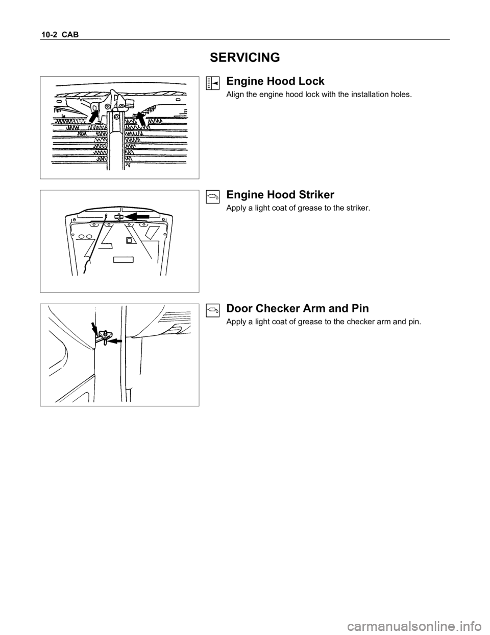
SERVICING
Engine Hood Lock
Align the engine hood lock with the installation holes.
Engine Hood Striker
Apply a light coat of grease to the striker.
Door Checker Arm and Pin
Apply a light coat of grease to the checker arm and pin.
Page 457 of 1600

CAB 10-3
WINDSHIELD AND BACK LIGHT GLASSES
GENERAL DESCRIPTION
This vehicle uses two types of safety glass: (1) laminated safety plate, for the windshield, and (2) solid tempered
safety plate, for the back glass.
The windshield glass is one-piece and is directly retained in the windshield opening by the adhesive.
When replacing a cracked windshield glass, it is very important that the cause of the glass breakage be determined
and the condition corrected before a new glass is installed. Otherwise, it is possible that a small obstruction or high
spot somewhere around the windshield opening will continue to crack or break the newly installed windshield. This
is especially true when the strain on the glass caused by this obstruction is increased by such conditions as wind
pressures, extremes of temperature, motion of the vehicle, etc. The procedure for removal of the windshield
applies to the complete windshield assembly.
WINDSHIELD GLASS BACK LIGHT GLASS